lock FORD FIESTA 2007 Owner's Guide
[x] Cancel search | Manufacturer: FORD, Model Year: 2007, Model line: FIESTA, Model: FORD FIESTA 2007Pages: 1226, PDF Size: 61.26 MB
Page 204 of 1226
206-00-32 Brake System - General Information 206-00-32
GENERAL PROCEDURES
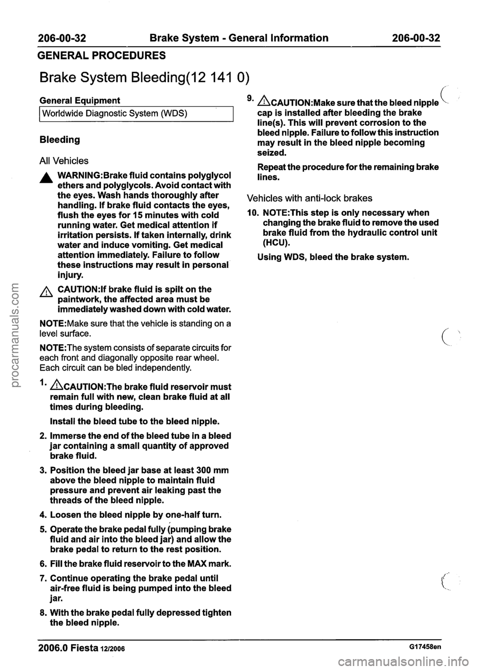
Brake System Bleeding(l2 141 0) /'. ,
All Vehicles Repeat the procedure for the remaining brake
A WARNING:Brake fluid contains polyglycol lines.
ethers and polyglycols. Avoid contact with
General
Equipment
9m ACAUTION:M~~~ sure that the bleed nipple
the eyes. Wash hands thoroughly after
Vehicles with anti-lock brakes handling. If brake fluid contacts the eyes,
flush the eyes for
15 minutes with cold 10. N0TE:This step is only necessary when
running water. Get medical attention
if changing the brake fluid to remove the used
irritation persists.
If taken internally, drink brake
fluid from the hydraulic control unit
water and induce vomiting. Get medical (HCU).
Worldwide
Diagnostic System (WDS)
attention immediately. Failure to follow
Using WDS, bleed the brake system.
these instructions may result in personal'
injury.
CAUTI0N:If brake fluid is spilt on the
paintwork, the affected area must be
immediately washed down with cold water. cap
is installed after bleeding the brake
N0TE:Make sure that the vehicle is standing on a
level surface.
line(s). This will prevent corrosion to the
bleed nipple. Failure to follow this instruction
Bleeding may result in the bleed nipple becoming
seized.
N0TE:The system consists of separate circuits for
each front and diagonally opposite rear wheel.
Each circuit can be bled independently.
ACAUTION:T~~ brake fluid reservoir must
remain full with new, clean brake fluid at all
times during bleeding.
Install the bleed tube to the bleed nipple.
2. Immerse the end of the bleed tube in a bleed
jar containing a small quantity of approved
brake fluid.
3. Position the bleed jar base at least 300 mm
above the bleed nipple to maintain fluid
pressure and prevent air leaking past the
threads of the bleed nipple.
4. Loosen the bleed nipple by one-half turn.
5. Operate the brake pedal fully ipumping brake
fluid and air into the bleed jar) and allow the
brake pedal to return to the rest position.
6. Fill the brake fluid reservoir to the MAX mark.
7. Continue operating the brake pedal until
air-free fluid is being pumped into the bleed
jar.
8. With the brake pedal fully depressed tighten
the bleed nipple.
2006.0 Fiesta IZIZOO~ GI 7458en
procarmanuals.com
Page 205 of 1226
206-00-33 Brake System - General Information 206-00-33
GENERAL PROCEDURES
Brake System Pressure Bleeding(l2 141 0)
Bleeding
i General Equipment Vehicles with anti-lock brakes
All vehicles
Worldwide Diagnostic System (WDS)
Brakelclutch system pressure bleederlfiller
A WARNING: Brake fluid contains polyglycol
ethers and polyglycols. Avoid contact with
the eyes. Wash hands thoroughly after
handling. If brake fluid contacts the eyes,
flush the eyes for
15 minutes with cold
running water. Get medical attention if
irritation persists. If taken internally, drink
water and induce vomiting. Get medical
attention immediately. Failure to follow
these instructions may result in personal
injury.
4. N0TE:This ste.p is only necessary when
changing the brake fluid to remove the used
A CAUTI0N:If brake fluid is spilt on the
paintwork, the affected area must be
immediately washed down with cold water.
/
brake fluid from the hydraulic control unit
I N0TE:Make sure that the vehicle is standing on a
level surface.
N0TE:The system consists of separate circuits for
each front and diagonally opposite rear wheel.
Each circuit can be bled independently.
I. Fill the brake fluid reservoir to the MAX mark.
2. CAUTIONS:
AMake sure that the pressure within the
brake system does not exceed
1 bar.
n~ake sure that the pressure bleeding
equipment is filled with new brake fluid to
the correct specification.
Using the
brakelclutch system pressure
bleederlfiller, pressure bleed the system in
accordance with the manufacturer's
instructions.
3n ACAUTION:M~~~ sure that the bleed nipple
cap is installed after bleeding the brake
line(s). This will prevent corrosion to the
bleed nipple. Failure to follow this instruction
I may result in the bleed nipple becoming
seized.
Fill the brake fluid reservoir to the
MAX mark
as necessary. (HCU).
Using
WDS, bleed the brake system.
2006.0 Fiesta 1212006
procarmanuals.com
Page 251 of 1226
206-05-1 5 Parking Brake and Actuation 206-05-1 5
REMOVAL AND INSTALLATION
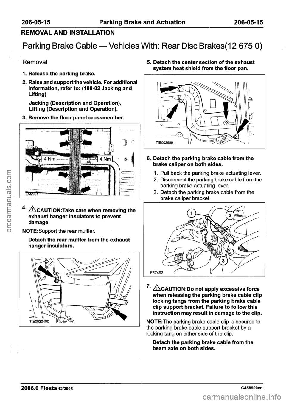
Parking Brake Cable - Vehicles With: Rear Disc Brakes(l2 675 0)
Removal
I. Release the parking brake.
2. Raise and support the vehicle. For additional
information, refer to:
(1 00-02 Jacking and
Lifting)
Jacking (Description and Operation),
Lifting (Description and Operation).
3. Remove the floor panel crossmember.
4m ACAUTION:T~~~ care when removing the
exhaust hanger insulators to prevent
damage.
N0TE:Support the rear muffler.
Detach the rear muffler from the exhaust
hanger insulators.
5. Detach the center section of the exhaust
system heat shield from the floor pan.
6. Detach the parking brake cable from the
brake caliper on both sides.
I. Pull back the parking brake actuating lever.
2. Disconnect the parking brake cable from the
parking brake actuating lever.
3. Detach the parking brake cable from the
brake caliper bracket.
ACAUTION:DO not apply excessive force
when releasing the parking brake cable clip
locking tangs from the parking brake cable
clip support bracket. Failure to follow this
instruction may result in damage to the clip.
N0TE:The parking brake cable clip is secured to
the parking brake cable support bracket by a
locking tang on either side of the clip.
Detach the parking brake cable from the
beam axle on both sides.
2006.0 Fiesta 1212006 G458900en
procarmanuals.com
Page 252 of 1226
206-05-1 6 Parking Brake and Actuation 206-05-1 6
REMOVAL AND INSTALLATION
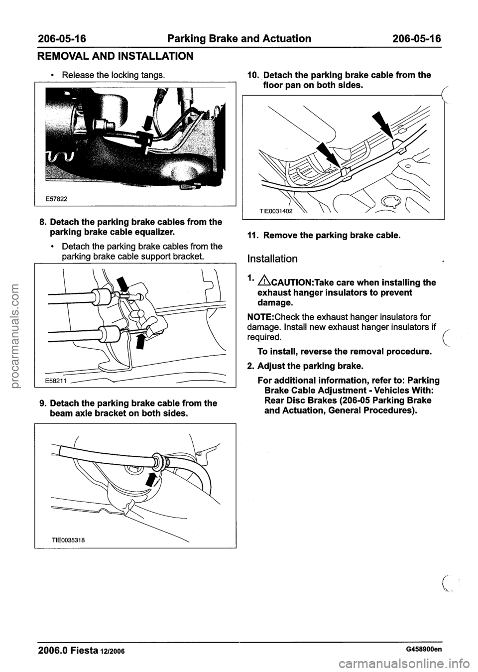
Release the locking tangs.
8. Detach the parking brake cables from the
parking brake cable equalizer.
Detach the parking brake cables from the
parking brake cable support bracket.
9. Detach the parking brake cable from the
beam axle bracket on both sides.
10. Detach the parking brake cable from the
floor pan on both sides.
11. Remove the parking brake cable.
Installation
ACAUTION:T~~~ care when installing the
exhaust hanger insulators to prevent
damage.
N0TE:Check the exhaust hanger insulators for
damage. Install new exhaust hanger insulators if
required.
To install, reverse the removal procedure.
2. Adjust the parking brake.
For additional information, refer to: Parking
Brake Cable Adjustment
- Vehicles With:
Rear Disc Brakes
(206-05 Parking Brake
and Actuation, General Procedures).
2006.0 Fiesta 1212006 G458900en
procarmanuals.com
Page 262 of 1226
206-06-8 Hydraulic Brake Actuation 206-06-8
REMOVAL AND INSTALLATION
Brake Master Cylinder - RHD(12 343 0)
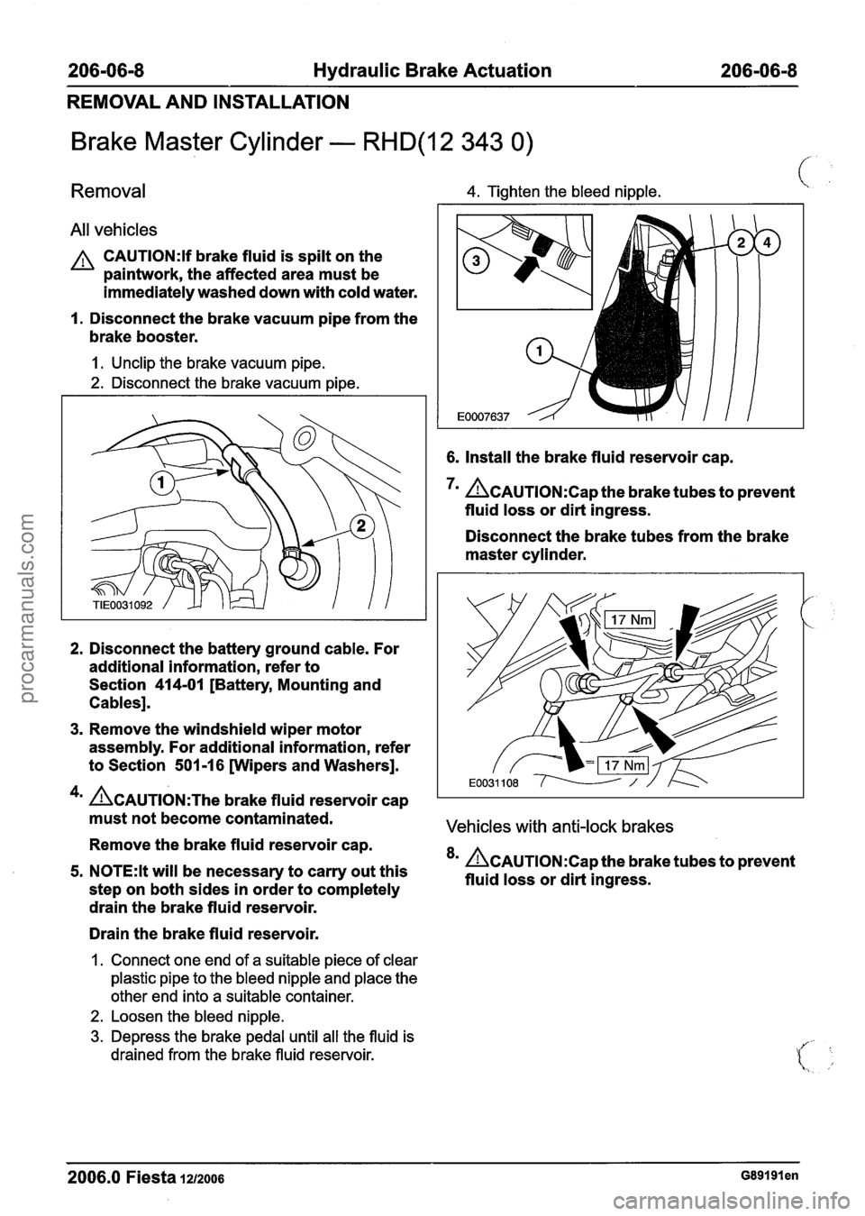
Removal 4. Tighten the bleed nipple. \,
All vehicles
CAUTI0N:lf brake fluid is spilt on the
paintwork, the affected area must be
immediately washed down with cold water.
I. Disconnect the brake vacuum pipe from the
brake booster.
I. Unclip the brake vacuum pipe.
2. Disconnect the brake vacuum pipe.
6. Install the brake fluid reservoir cap.
7m &AUTION:C~~ the brake tubes to prevent
fluid loss or dirt ingress.
Disconnect the brake tubes from the brake
master cylinder.
2. Disconnect the battery ground cable. For
additional information, refer to
Section
414-01 [Battery, Mounting and
Cables].
3. Remove the windshield wiper motor
assembly. For additional information, refer
to Section
501 -1 6 [Wipers and Washers].
4m &AUTION:T~~ brake fluid reservoir cap
must not become contaminated.
Vehicles with anti-lock brakes
Remove the brake fluid reservoir cap.
5. N0TE:lt will be necessary to carry out this 8m &AUTION:C~~ the brake tubes to prevent
fluid loss or dirt ingress.
step on both sides in order to completely
drain the brake fluid reservoir.
Drain the brake fluid reservoir.
1. Connect one end of a suitable piece of clear
plastic pipe to the bleed nipple and place the
other end into a suitable container.
2. Loosen the bleed nipple.
3. Depress the brake pedal until all the fluid is
drained from the brake fluid reservoir.
2006.0 Fiesta 1212006 ~89191 en
procarmanuals.com
Page 267 of 1226
206-0713 Power Brake Actuation 206-0713
DESCRIPTION AND OPERATION
Brake Booster
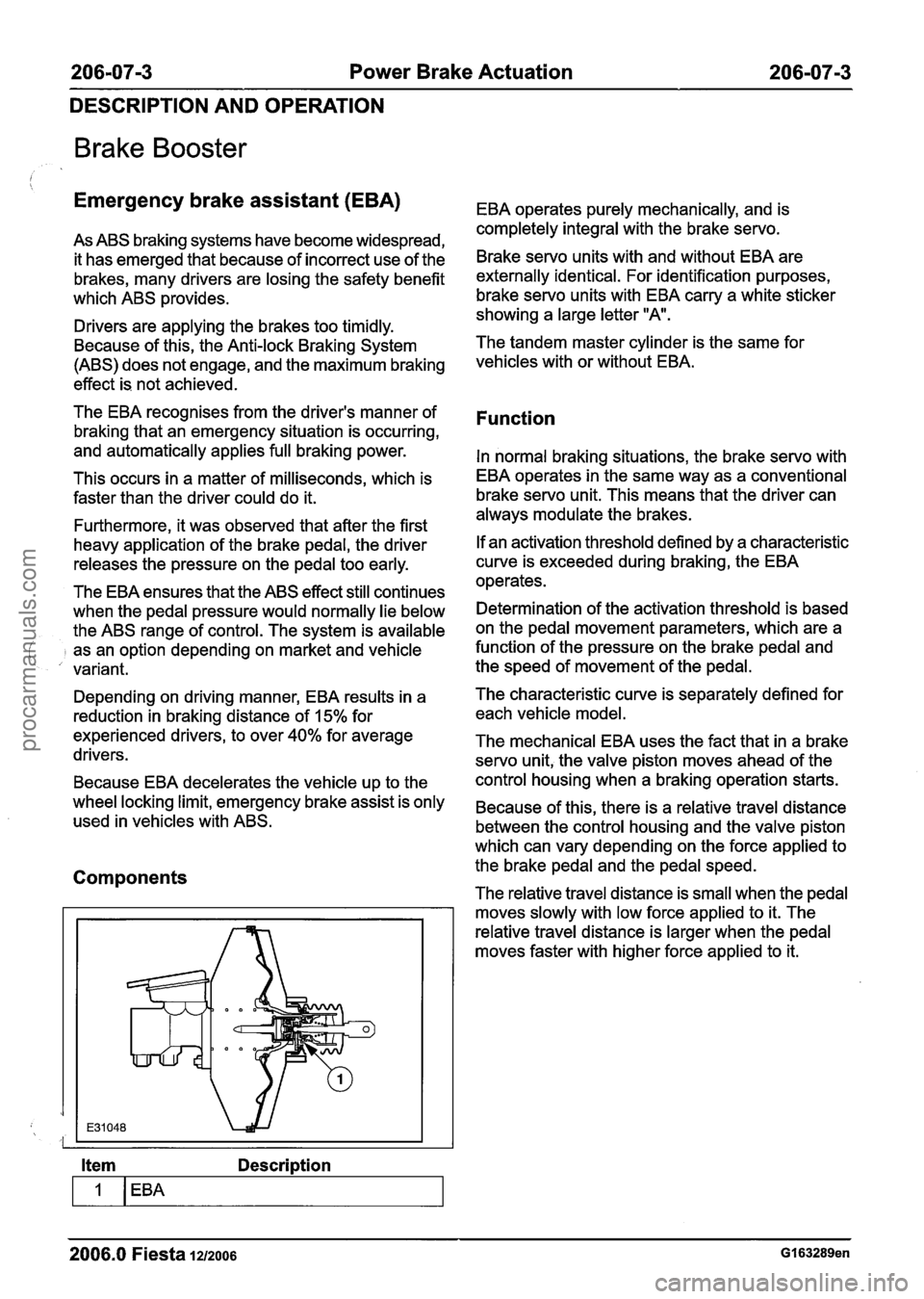
Emergency brake assistant (EBA) EBA operates purely mechanically, and is
completely integral with the brakeservo.
As ABS braking systems have become widespread,
it has emerged that because of incorrect use of the
Brake servo units with and without EBA are
brakes, many drivers are losing the safety benefit externally identical. For identification purposes,
which ABS
~rovides. brake servo units with EBA carry a white sticker I showing a large letter "A. Drivers are applying the brakes too timidly.
Because of this, the Anti-lock Braking System The tandem master cylinder
is the same for
(ABS) does not engage, and the maximum braking
vehicles with or without
effect is not achieved.
The EBA recognises from the driver's manner of
braking that an emergency situation is occurring,
and automatically applies full braking power.
This occurs in a matter of milliseconds, which is
faster than the driver could do it.
Furthermore, it was observed that after the first
heavy application of the brake pedal, the driver
releases the pressure on the pedal too early.
The EBA ensures that the ABS effect still continues
when the pedal pressure would normally lie below
the ABS range of control. The system is available
j as an option depending on market and vehicle
variant.
Function
In normal braking situations, the brake servo with
EBA operates in the same way as a conventional
brake servo unit. This means that the driver can
always modulate the brakes.
If an activation threshold defined by a characteristic
curve is exceeded during braking, the EBA
operates.
Determination of the activation threshold is based
on the pedal movement parameters, which are a
function of the pressure on the brake pedal and
the speed of movement of the pedal.
Depending on driving manner, EBA results in a The characteristic curve
is separately defined for
reduction in braking distance of 15% for each vehicle model.
experienced drivers, to over
40% for average The mechanical EBA uses the fact that in a brake
drivers. servo unit, the valve piston moves ahead of the
Because EBA decelerates the vehicle up to the control housing
when a braking operation starts.
wheel locking limit, emergency brake assist is only Because of this, there is a relative travel distance used in vehicles with ABS.
between the control housing and the valve piston
which can vary depending on the force applied to
Components the brake pedal and the pedal speed.
The relative travel distance is small when the pedal
moves slowly with low force applied to it. The
relative travel distance is larger when the pedal
moves faster with higher force applied to it.
Item Description
-
2006.0 Fiesta 1212006 GI 63289en
procarmanuals.com
Page 269 of 1226
206-07-5 Power Brake Actuation 206-07-5
DESCRIPTION AND OPERATION
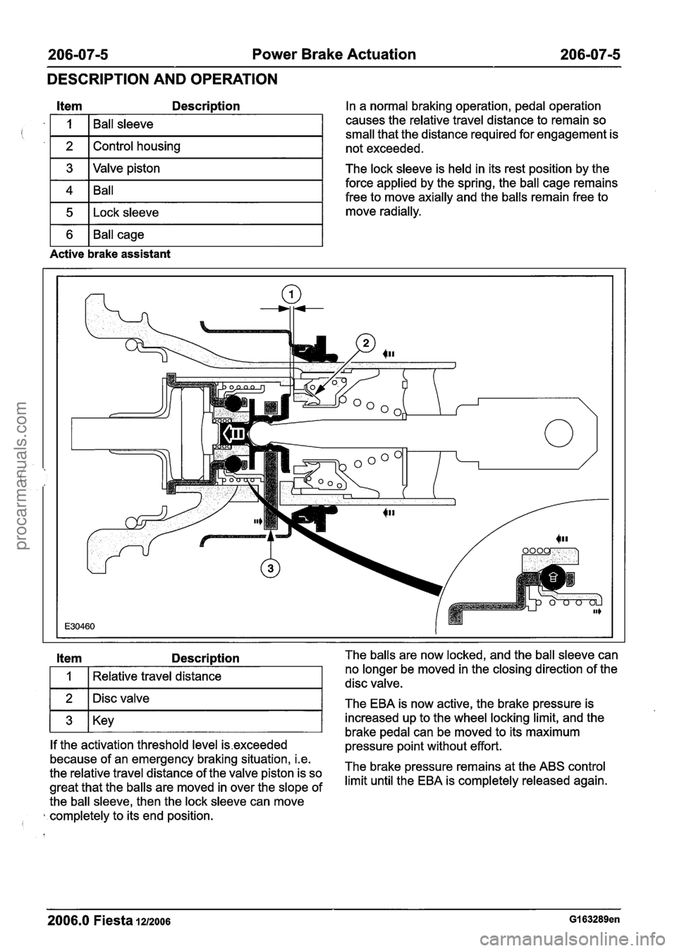
Item Description
1 3 I Valve piston I
i '
1 4 1 Ball I
1 5 1 ~ock sleeve I
I
2
1 6 1 Ball cage I
Ball sleeve
Control housing
Active brake assistant
In a normal braking operation, pedal operation
causes the relative travel distance to remain so
small that the distance required for engagement is
not exceeded.
The lock sleeve is held in its rest position by the
force applied by the spring, the ball cage remains
free to move axially and the balls remain free to
move radially.
Item Description
I 1 I Relative travel distance I
1 2 1 Disc valve I -
1 3 1 Key I
If the activation threshold level is.exceeded
because of an emergency braking situation, i.e.
the relative travel distance of the valve piston is so
great that the balls are moved in over the slope of
the ball sleeve, then the lock sleeve can move
completely to its end position.
I
--
The balls are now locked, and the ball sleeve can
no longer be moved in the closing direction of the
disc valve.
The EBA is now active, the brake pressure is
increased up to the wheel locking limit, and the
brake pedal can be moved to its maximum
pressure point without effort.
The brake pressure remains at the ABS control
limit until the EBA is completely released again.
2006.0 Fiesta 1212006 GI 63289en
procarmanuals.com
Page 270 of 1226
206-0716 Power Brake Actuation 206-0716
DESCRIPTION AND OPERATION
Release of the brake assistant
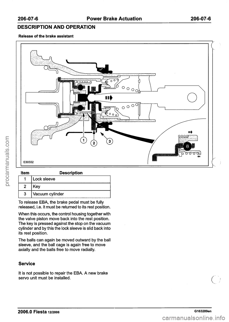
Item Description
I I I ~ock sleeve I
1 3 IVacuum cylinder I
To release EBA, the brake pedal must be fully
released,
i.e. it must be returned to its rest position.
When this occurs, the control housing together with
the valve piston move back into the rest position.
The key is pressed against the stop on the vacuum
cylinder and by this the lock sleeve is slid back into
its rest position.
The balls can again be moved outward by the ball
sleeve, and the ball cage is again free to move
axially and the balls free to move radially.
Service
It is not possible to repair the EBA. A new brake
servo unit must be installed.
2006.0 Fiesta 12/2006 GI 63289en
procarmanuals.com
Page 272 of 1226
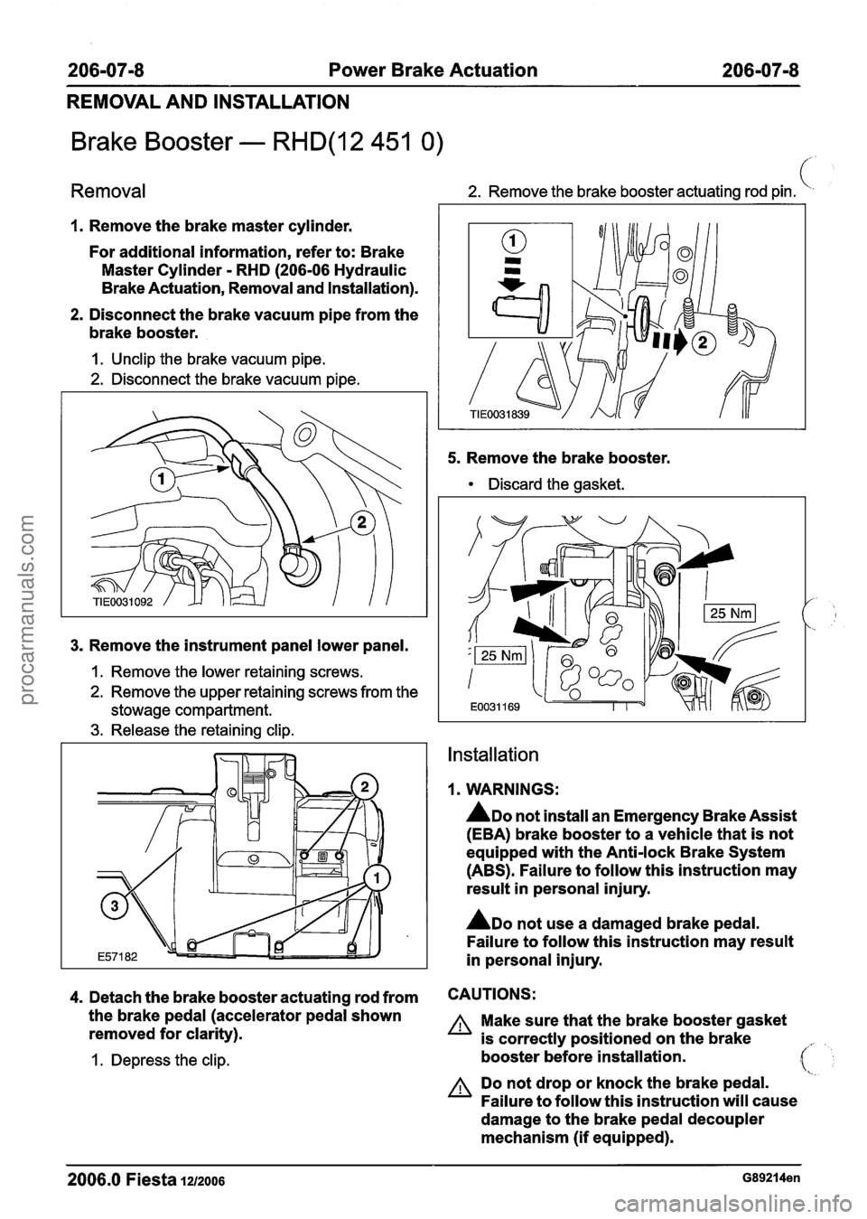
206-07-8 Power Brake Actuation 206-07-8
REMOVAL AND INSTALLATION
Brake Booster - RHD(12 451 0)
Removal 2. Remove the brake booster actuating rod pin. (
1. Remove the brake master cylinder.
For additional information, refer to: Brake
Master Cylinder
- RHD (206-06 Hydraulic
Brake Actuation, Removal and Installation).
2. Disconnect the brake vacuum pipe from the
brake booster.
I. Unclip the brake vacuum pipe.
2. Disconnect the brake vacuum pipe.
3. Remove the instrument panel lower panel.
1. Remove the lower retaining screws.
2. Remove the upper retaining screws from the
stowage compartment.
3. Release the retaining clip. 5.
Remove
the brake booster.
Discard the gasket.
Installation
1. WARNINGS:
ADO not install an Emergency Brake Assist
(EBA) brake booster to a vehicle that is not
equipped with the Anti-lock Brake System
(ABS). Failure to follow this instruction may
result in personal injury.
ADO not use a damaged brake pedal.
Failure to follow this instruction may result
in personal injury.
4. Detach the brake booster actuating rod from CAUTIONS:
the brake pedal (accelerator pedal shown A Make sure that the brake booster gasket
removed for clarity).
is correctly positioned on the brake
I. Depress the clip. booster before installation. 41
A Do not drop or knock the brake pedal.
Failure to follow this instruction will cause
damage to the brake pedal decoupler
mechanism (if equipped).
2006.0 Fiesta 12/2006 G89214en
procarmanuals.com
Page 275 of 1226
206-09A-1 Anti-Lock Control 206-09A-I
SECTION 206-09A Anti-Lock Control
CONTENTS
PAGE
SPECIFICATIONS
........................................................................\
.............................................. Specifications 206-09A-2
DESCRIPTION AND OPERATION
........................................................................\
......................................... Anti-Lock Control 206-09A-3
........................................................................\
..................................................... Overview 206-09A-3
Function
........................................................................\
...................................................... 206-09A-3
Anti-Lock Control
........................................................................\
........................................ 206-09A-5
MK70 Anti-lock Brake System (ABS) ........................................................................\
......... 206-09A-5
........................................................................\
.................................................. MK60 ABS 206-09A-5
DIAGNOSIS AND TESTING
........................................................................\
........................................ Anti-Lock Control 206-09A-7
........................................................................\
.......................... Inspection and Verification 206-09A-7
REMOVAL AND INSTALLATION
......................................... Hydraulic Control Unit (HCU) -- Vehicles Built Up To: 0512004 206-09A-8
.......................................... Hydraulic Control Unit (HCU) -- Vehicles Built From: 0512004 206-09A-11
Anti-Lock Brake System (ABS) Module -- Vehicles Built Up To: 0512004 ......................... 206-09A-14
.......................... Anti-Lock Brake System (ABS) Module -- Vehicles Built From: 0512004 206-09A-17
........................................................................\
..... Rear Wheel Speed Sensor
(12 785 0) 206-09A-20
Rear Wheel Speed Sensor Ring
................................................................... (12 788 0) 206-09A-22
Front Wheel Speed Sensor
........................................................................\
.... (12 784 0) 206-09A-24
procarmanuals.com