engine coolant FORD FIESTA 2007 Service Manual
[x] Cancel search | Manufacturer: FORD, Model Year: 2007, Model line: FIESTA, Model: FORD FIESTA 2007Pages: 1226, PDF Size: 61.26 MB
Page 627 of 1226
303-01 B-5 Engine - 2.OL Duratec-HE (M14) 303-01 B-5
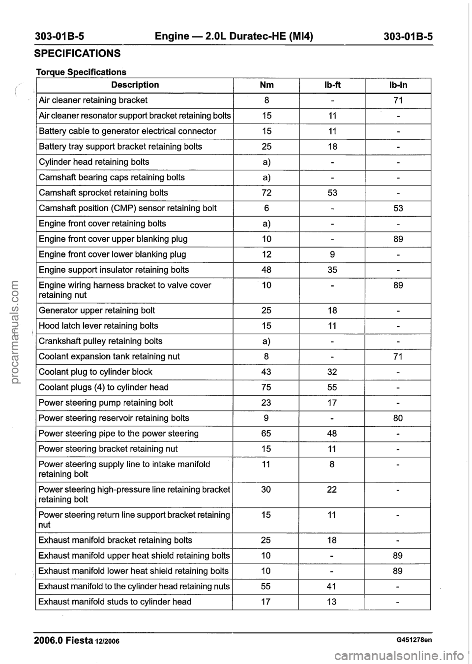
SPECIFICATIONS
Torque Specifications - --- -- - -- -
Description Nm l b-ft Ib-in
Air cleaner retaining bracket
Air cleaner resonator support bracket retaining bolts Battery cable to generator electrical connector
I Cylinder head retaining bolts I a) I - I - I
Battery tray support bracket retaining bolts
I
--
I Camshaft bearing caps retaining bolts a) IT
15
15
I Camshaft sprocket retaining bolts I 72 I 53 I - I
25
I Camshaft position (CMP) sensor retaining bolt I 6 1 - I 53 I
11
I1
-
-
18
I Engine front cover lower blanking plug I 12 I 9 I - I
-
Engine front cover retaining bolts
Engine front cover upper blanking plug
I Engine support insulator retaining bolts I 48 I 35 I - I
Engine wiring harness bracket to valve cover
retaining nut
a)
10
I Generator upper retaining bolt I 25 I 18 I - I
-
-
I Coolant plugs (4) to cylinder head I 75 I 55 I - I
-
89
Hood latch lever retaining bolts
Crankshaft pulley retaining bolts
Coolant expansion tank retaining nut
Coolant plug to cylinder block
I Power steering pump retaining bolt I 23 I 17 I - I
15
a)
8
43
I
--
I Power steering bracket retaining nut 15 IT
Power steering reservoir retaining bolts
Power steering pipe to the power steering
Power steering supply line to intake manifold
retaining bolt
11
-
-
32
Power steering high-pressure line retaining bracket
retaining bolt
-
-
71
-
9
65
I Power steering return line support bracket retaining I 15 I 11 I - I
1 nut
-
48 80 -
Exhaust
manifold bracket retaining bolts
2006.0 Fiesta 1212006 G451278en
Exhaust manifold upper heat shield retaining bolts
Exhaust manifold lower heat shield retaining bolts
Exhaust manifold to the cylinder head retaining nuts
Exhaust manifold studs to cylinder head
25
10
10
55
17 18
-
-
-
41
13 89
89 -
-
procarmanuals.com
Page 628 of 1226
,303-01 B-6 Engine - 2.OL Duratec-HE (M14) 303-01 B-6
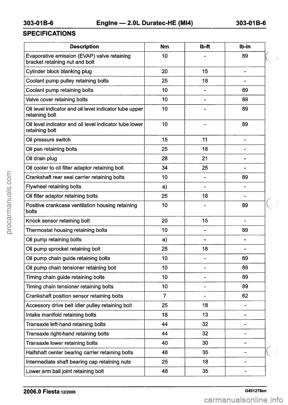
SPECIFICATIONS
I Description I Nm' I Ib-ft I Ib-in I
Evaporative emission (EVAP) valve retaining
bracket retaining nut and bolt
Valve cover retaining bolts
I 10 I - I 89 I
Cylinder block blanking plug
Coolant pump pulley retaining bolts
Coolant pump retaining bolts
Oil level indicator and oil level indicator tube upper
retaining bolt
Oil level indicator and oil level indicator tube lower
retaining bolt 20
25
10
Oil pressure switch I 15 I 11 I - I
I Oil pan retaining bolts
15
18
-
-
-
89
I Crankshaft rear seal carrier retaining bolts I 10 I - I 89 I
Oil drain plug
Oil cooler to oil filter adaptor retaining bolt
I Flywheel retaining bolts I a) I - I - I
28
34
I Knock sensor retaining bolt I 20 I 15 I - I
Oil filter adaptor retaining bolts
Positive crankcase ventilation housing retaining
bolts
I Thermostat housing retaining bolts I 10 I - I 89 I
21
25
I Oil pump retaining bolts I a) I - I - I
-
-
25
10
I Oil pump sprocket retaining bolt I 25 I 18 I - I
18
-
-
89
Oil pump chain guide retaining bolts
Oil pump chain tensioner retaining bolt
I Crankshaft position sensor retaining bolts I 7 I - I 62 I
Timing chain guide retaining bolts
Timing chain tensioner retaining bolts
I Accessory drive belt idler pulley retaining bolt I 25 I 18 I - I
10
10
I Intake manifold retaining bolts I 18 I 13 I - I
10
10
I Transaxle left-hand retaining bolts I 44 I 32 I - I
-
-
I Transaxle right-hand retaining bolts I 44 I 32 I - I
89
89
-
-
89
89
Transaxle lower retaining bolts
Halfshaft center bearing carrier retaining bolts
I Lower arm ball joint retaining bolt I 48 I 35 I - I
Intermediate shaft bearing cap retaining nuts
2006.0 Fiesta 1212006 G451278en
40
48
25 30
35 -
-
18 -
procarmanuals.com
Page 631 of 1226
303101 B-9 Engine - 2.OL Duratec-HE (M14) 303-01 B-9
DESCRIPTION AND OPERATION
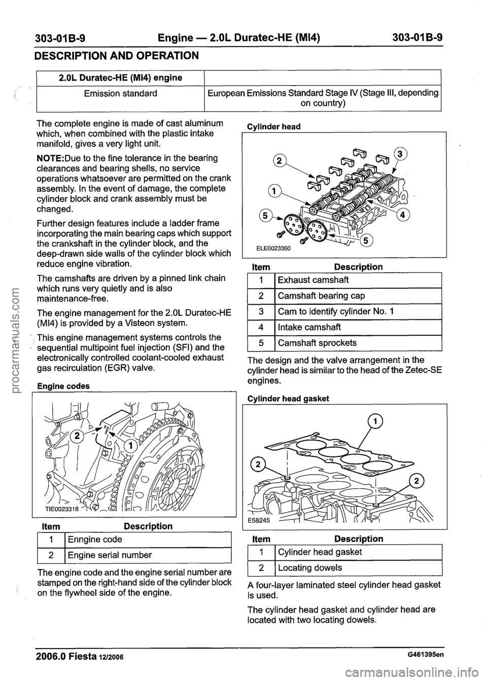
The complete engine is made of cast aluminum
which, when combined with the plastic intake
manifold, gives a very light unit.
2.OL Duratec-HE (M14) engine
Emission standard
N0TE:Due to the fine tolerance in the bearing
clearances and bearing shells, no service
operations whatsoever are permitted on the crank
assembly. In the event of damage, the complete
cylinder block and crank assembly must be
changed. European
Emissions Standard Stage
IV (Stage II I, depending
on country)
Further design features include a ladder frame
incorporating the main bearing caps which support
the crankshaft in the cylinder block, and the
deep-drawn side walls of the cylinder block which
reduce engine vibration.
The camshafts are driven by a pinned link chain
which runs very quietly and is also
maintenance-free.
Cvlinder head
Item Description
1
2
The engine management for the 2.OL Duratec-HE
(M14) is provided by a Visteon system.
Item Description
Exhaust camshaft
Camshaft bearing cap
', This engine management systems controls the ' , sequential multipoint fuel injection (SFI) and the
I 1 (Enngine code I
3
4
wl~n~ine serial number I
Cam to identify cylinder No. 1
Intake camshaft
ele~tronically controlled coolant-cooled exhaust The design and the valve arrangement in the gas recirculation (EGR) valve.
cylinder head is similar to the head of the Zetec-SE
engines.
Enaine codes
5
The engine code and the engine serial number are
stamped on the right-hand side of the cylinder block
on the flywheel side of the engine. Camshaft sprockets
Cvlinder
head gasket
Item Description
I 1 I Cylinder head gasket I
1 2 1 Locating dowels 1
A four-layer laminated steel cylinder head gasket
is used.
The cylinder head gasket and cylinder head are
located with two locating dowels.
2006.0 Fiesta 1212006 G461395en
procarmanuals.com
Page 682 of 1226
303-01 B-60 Engine - 2.OL Duratec-HE (M14) 303-01 B-60
IN-VEHICLE REPAIR
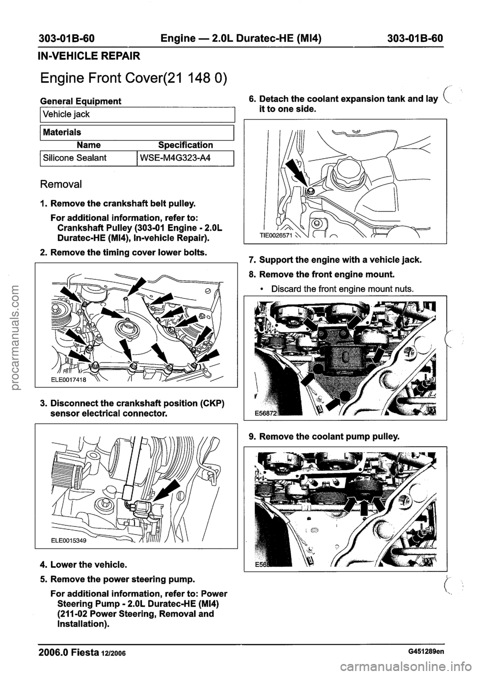
Engine Front Cover(21 148 0)
f'
General Equipment 6. Detach the coolant expansion tank and lay
I Vehicle jack it to one side.
Materials Name Specification
I Silicone Sealant I WSE-M4G323-A4 I
Removal
1. Remove the crankshaft belt pulley.
For additional information, refer to:
Crankshaft Pulley (303-01 Engine
- 2.OL
Duratec-HE (M14), Invehicle Repair).
2. Remove the timing cover lower bolts.
7. Support the engine with
a vehicle jack.
8. Remove the front engine mount.
Discard the front engine mount nuts.
3. Disconnect the crankshaft position (CKP)
sensor electrical connector.
4. Lower the vehicle.
5. Remove the power steering pump.
For additional information, refer to: Power
Steering Pump
- 2.OL Duratec-HE (M14)
(211 -02 Power Steering, Removal and
Installation).
9. Remove the coolant pump pulley.
2006.0 Fiesta 121~0o6 G451289en
procarmanuals.com
Page 684 of 1226
303-01 B-62 Engine - 2.OL Duratec-HE (M14) 303-01 B-62
IN-VEHICLE REPAIR
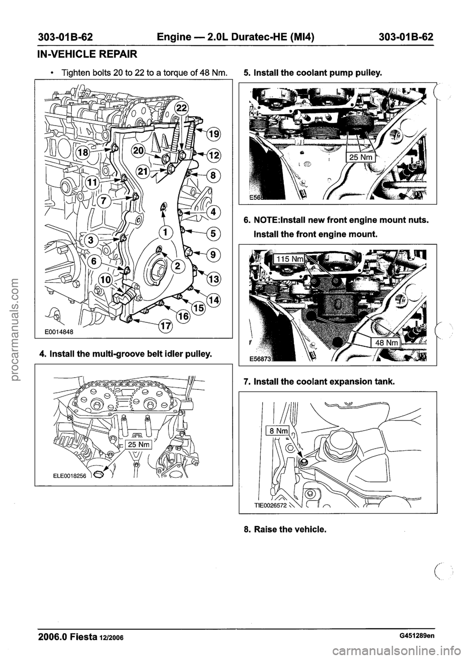
Tighten bolts 20 to 22 to a torque of 48 Nm. 5. Install the coolant pump pulley.
4. Install the multi-groove belt idler pulley.
6. N0TE:lnstall new front engine mount nuts.
Install the front engine mount.
7, Install the coolant expansion tank.
8. Raise the vehicle.
2006.0 Fiesta 1212006 G451289en
procarmanuals.com
Page 691 of 1226
303-01 B-69 Engine - 2.OL Duratec-HE (M14) 303-01 B-69
IN-VEHICLE REPAIR
Cylinder Head(21 163 0)
Special Tool(s) 5. Remove the timing chain.
I Materials I
24003
I I Name Specification
Remover/lnstaller, Hose
Clamp
303-397
Removal
For additional information, refer to: Timing
Chain (303-01 Engine
- 2.OL Duratec-HE
(M14), Invehicle Repair).
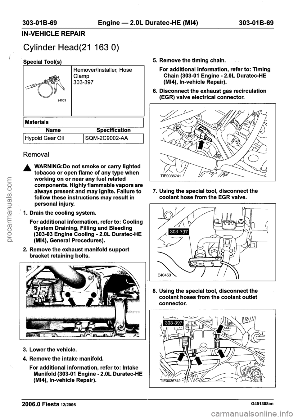
6. Disconnect the exhaust gas recirculation
(EGR) valve electrical connector.
Hypoid Gear Oil
A WARNING:Do not smoke or carry lighted
tobacco or open flame of any type when
working on or near any fuel related
components. Highly flammable vapors are
always present and may ignite. Failure to
7. Using the special tool, disconnect the
follow these instructions may result in coolant hose
from the EGR valve.
personal injury.
/
SQM-2C9002-AA
( I. Drain the cooling system.
For additional information, refer to: Cooling
System Draining, Filling and Bleeding
(303-03 Engine Cooling
- 2.OL Duratec-HE
(M14), General Procedures).
2. Remove the exhaust manifold support
bracket retaining bolts.
3. Lower the vehicle.
4. Remove the intake manifold.
For additional information, refer to: Intake
Manifold (303-01 Engine
- 2.OL Duratec-HE
(M14), In-vehicle Repair).
8. Using the special tool, disconnect the
coolant hoses from the coolant outlet
connector.
2006.0 Fiesta 1212006 G451308en
procarmanuals.com
Page 692 of 1226
303-01 B-70 Engine - 2.OL Duratec-HE (M14) 303-01 B-70
IN-VEHICLE REPAIR
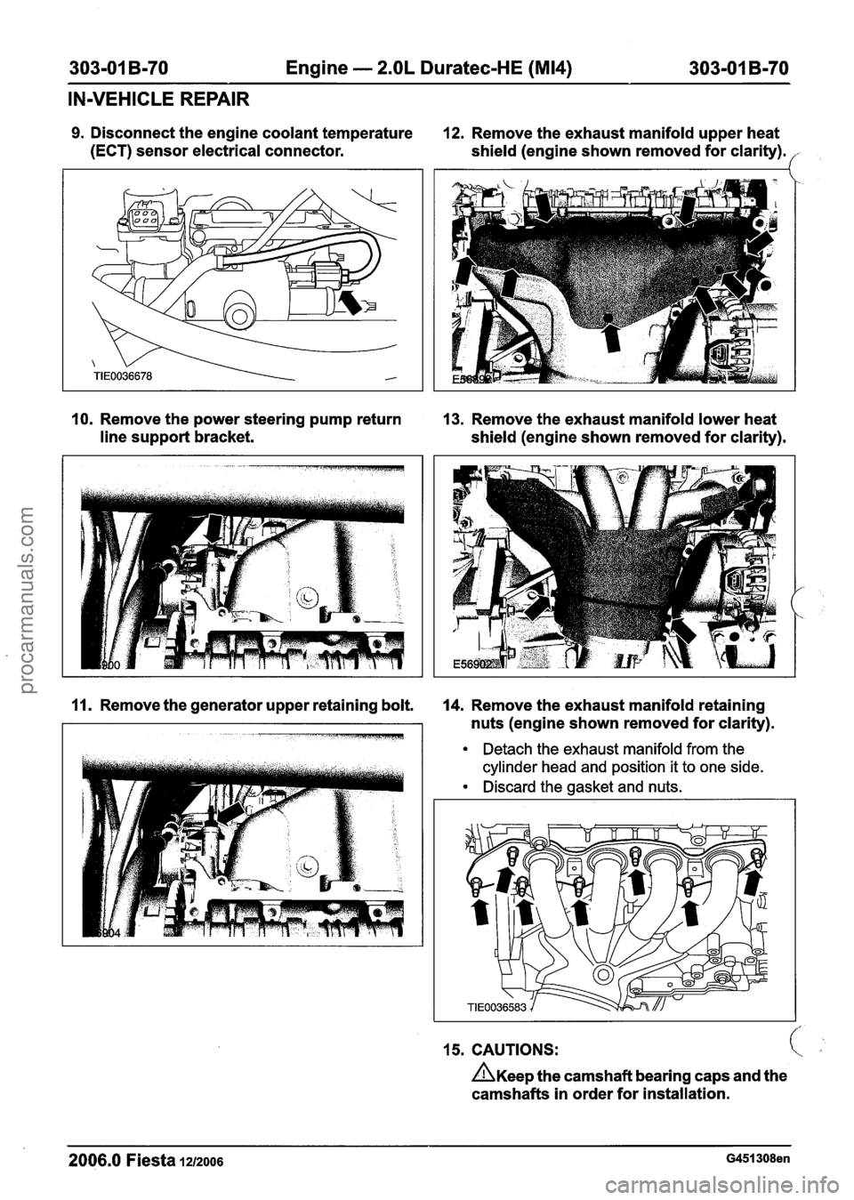
9. Disconnect the engine coolant temperature 12. Remove the exhaust manifold upper heat
(ECT) sensor electrical connector.
shield (engine shown removed for clarity).
('
10. Remove the power steering pump return 13. Remove the exhaust manifold lower heat
line support bracket.
shield (engine shown removed for clarity).
11. Remove the generator upper retaining bolt. 14. Remove the exhaust manifold retaining
nuts (engine shown removed for clarity).
Detach the exhaust manifold from the
cylinder head and position it to one side.
Discard the gasket and nuts.
15. CAUTIONS: c
n~ee~ the camshaft bearing caps and the
camshafts in order for installation.
2006.0 Fiesta 12/2006 G451308en
procarmanuals.com
Page 694 of 1226

303-01 B-72 Engine - 2.OL Duratec-HE (M14) 303-01 B-72
IN-VEHICLE REPAIR
Check the valve clearance and adjust if 9. Using the special tool, connect the coolant
necessary. hose to the EGR valve.
/
For additional information, refer to: Valve
Clearance Adjustment
(303-01 Engine - 2.OL
Duratec-HE (M14), General Procedures).
6. Connect the engine coolant temperature
(ECT) sensor electrical connector.
7. Using the special tool, connect the coolant
hoses to the coolant outlet connector.
8. Connect the exhaust gas recirculation (EGR)
valve electrical connector. 10.
N0TE:lnstall a
new exhaust manifold gasket
and nuts.
Tighten the exhaust manifold retaining nuts
(engine shown removed for clarity).
11. Install the exhaust manifold lower heat
shield (engine shown removed for clarity).
2006.0 Fiesta 1212006 G451308en
procarmanuals.com
Page 697 of 1226
303-01 B-75 Engine - 2.OL Duratec-HE (M14) 303-01 B-75
REMOVAL
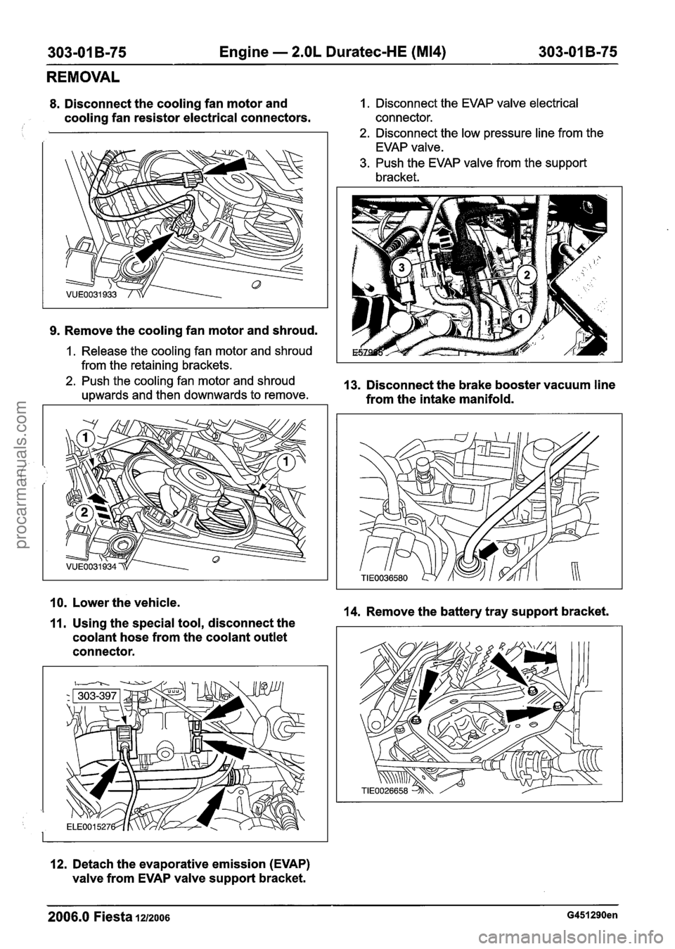
8. Disconnect the cooling fan motor and 1. Disconnect the EVAP valve electrical
cooling fan resistor electrical connectors. connector. 1 2. Disconnect the low pressure line from the
EVAP valve.
3. Push the EVAP valve from the support
bracket.
9. Remove the cooling fan motor and shroud.
1. Release the cooling fan motor and shroud
from the retaining brackets.
2. Push the cooling fan motor and shroud 13. Disconnect the brake booster vacuum line upwards and then downwards to remove. from the intake manifold.
10. Lower the vehicle. 14. Remove the battery tray support bracket.
11. Using the special tool, disconnect the
coolant hose from the coolant outlet
connector.
12. Detach the evaporative emission (EVAP)
valve from EVAP valve support bracket.
2006.0 Fiesta 1212006 G451290en
procarmanuals.com
Page 698 of 1226
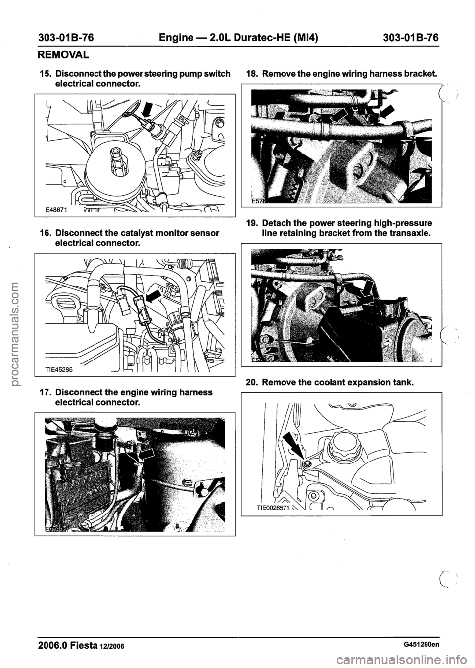
303-01 B-76 Engine - 2.OL Duratec-HE (M14) 303-01 B-76
REMOVAL
15. Disconnect the power steering pump switch 18. Remove the engine wiring harness bracket.
electrical connector.
I
19. Detach the power steering high-pressure
16. Disconnect the catalyst monitor sensor
line retaining bracket from the transaxle.
electrical connector.
20. Remove the coolant expansion tank.
17. Disconnect the engine wiring harness
electrical connector.
2006.0 Fiesta 1212006 G451290en
procarmanuals.com