engine coolant FORD FIESTA 2007 Owner's Guide
[x] Cancel search | Manufacturer: FORD, Model Year: 2007, Model line: FIESTA, Model: FORD FIESTA 2007Pages: 1226, PDF Size: 61.26 MB
Page 588 of 1226
303-01 A-I 12
Engine - 1.25L Duratec-1 6V (Sigma)ll.4L
Duratec-1 6V (Sigma)/lm6L Duratec-1 6V (Sigma)
ASSEMBLY
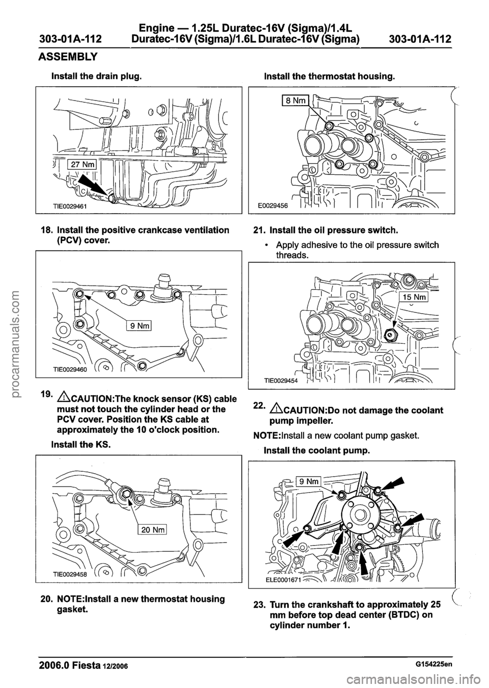
lnstall the drain plug.
lnstall the thermostat housing.
18. Install the positive crankcase ventilation 21. Install the oil pressure switch.
(PCV) cover.
Apply adhesive to the oil pressure switch
threads.
19' ~CAUTION:T~~ knock sensor (KS) cable
must not touch the cylinder head or the
PCV cover. Position the KS cable at
approximately the
10 o'clock position.
lnstall the KS.
20. N0TE:lnstall a new thermostat housing
gasket.
22' ACAUTION:D~ not damage the coolant
pump impeller.
N0TE:lnstall a new coolant pump gasket.
lnstall the coolant pump.
23, Turn the crankshaft to approximately 25
mm before top dead center (BTDC) on
cylinder number
I.
2006.0 Fiesta 1212006 GI 54225en
procarmanuals.com
Page 595 of 1226
Engine - 1.25L Duratec-1 6V (Sigma)llm4L
303-OIA-119 Duratec-1 6V (Sigma)llI6L Duratec-1 6V (Sigma) 303-01 A-1 19
ASSEMBLY
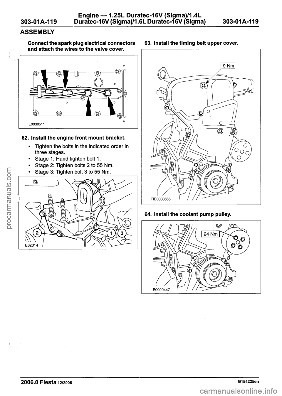
Connect the spark plug electrical connectors 63. Install the timing belt upper cover.
and attach the wires to the valve cover.
I
62. Install the engine front mount bracket.
Tighten the bolts in the indicated order in
three stages.
Stage 1 : Hand tighten bolt 1.
Stage 2: Tighten bolts 2 to 55 Nm.
Stage 3: Tighten bolt 3 to 55 Nm.
64. Install the coolant pump pulley.
2006.0 Fiesta 1~1zoo6 GI 54225en
procarmanuals.com
Page 600 of 1226

Engine - 1.25L Duratec-1 6V (Sigma)ll.4L
303-01 A-I 24 Duratec-1 6V (Sigma)/l .6L Duratec-1 6V (Sigma)
303-01 A-1 24
INSTALLATION
Attach the right-hand halfshaft and the Install the heat shield.
intermediate shaft to the transaxle.
13. CAUTIONS:
Asupport the halfshaft. The inner joint
must not be bent more than
18 degrees.
The outer joint must not be bent more than
45 degrees.
ADO not damage the halfshaft oil seal.
A~ake sure the snap ring is correctly
seated.
N0TE:lnstall a new snap ring.
Attach the left-hand halfshaft to the
transaxle.
14. Attach the lower arm to the wheel knuckle
on both sides (right-hand side shown).
15. Using the special tool, connect the coolant
hose to the distribution pipe
16. Using the special tool, connect the coolant
hose to the radiator.
2006.0 Fiesta 1212006 Gll3164en
procarmanuals.com
Page 605 of 1226
303-01 A-I 29 Engine
- 1.25L Duratec-I
6V (Sigma)ll.4L
Duratec-I 6V (Sigma)/l .6L Duratec-1 6V (Sigma) 303-01A-129
INSTALLATION
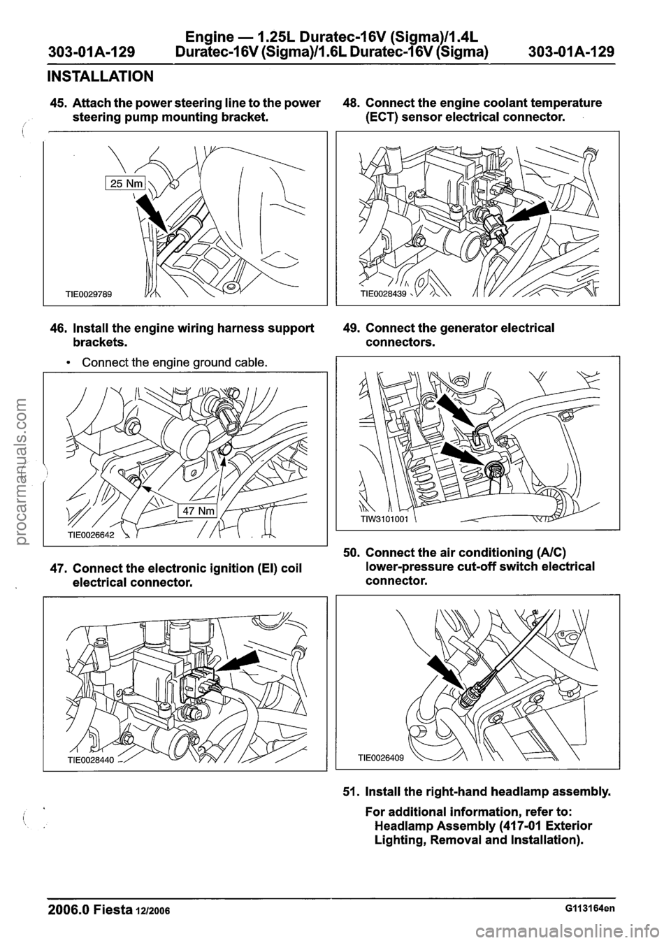
45. Attach the power steering line to the power 48.
Connect the engine coolant temperature
i steering pump mounting bracket. (ECT) sensor electrical connector.
46, Install the engine wiring harness support 49.
Connect the generator electrical
brackets. connectors.
Connect the engine ground cable.
50. Connect the air conditioning (AIC)
47. Connect the electronic ignition (El) coil lower-pressure
cut-off switch electrical
electrical connector. connector.
51. Install the right-hand
headlamp assembly.
For additional information, refer to:
Headlamp Assembly (41 7-01 Exterior
Lighting, Removal and Installation).
2006.0 Fiesta 1212006 GI 131 64en
procarmanuals.com
Page 607 of 1226
Engine - 1.25L Duratec-1 6V (Sigma)ll.4L
303-OIA-I31 Duratec-1 6V (Sigma)/l .6L Duratec-1 6V (Sigma) 303-01 A-1 31
INSTALLATION
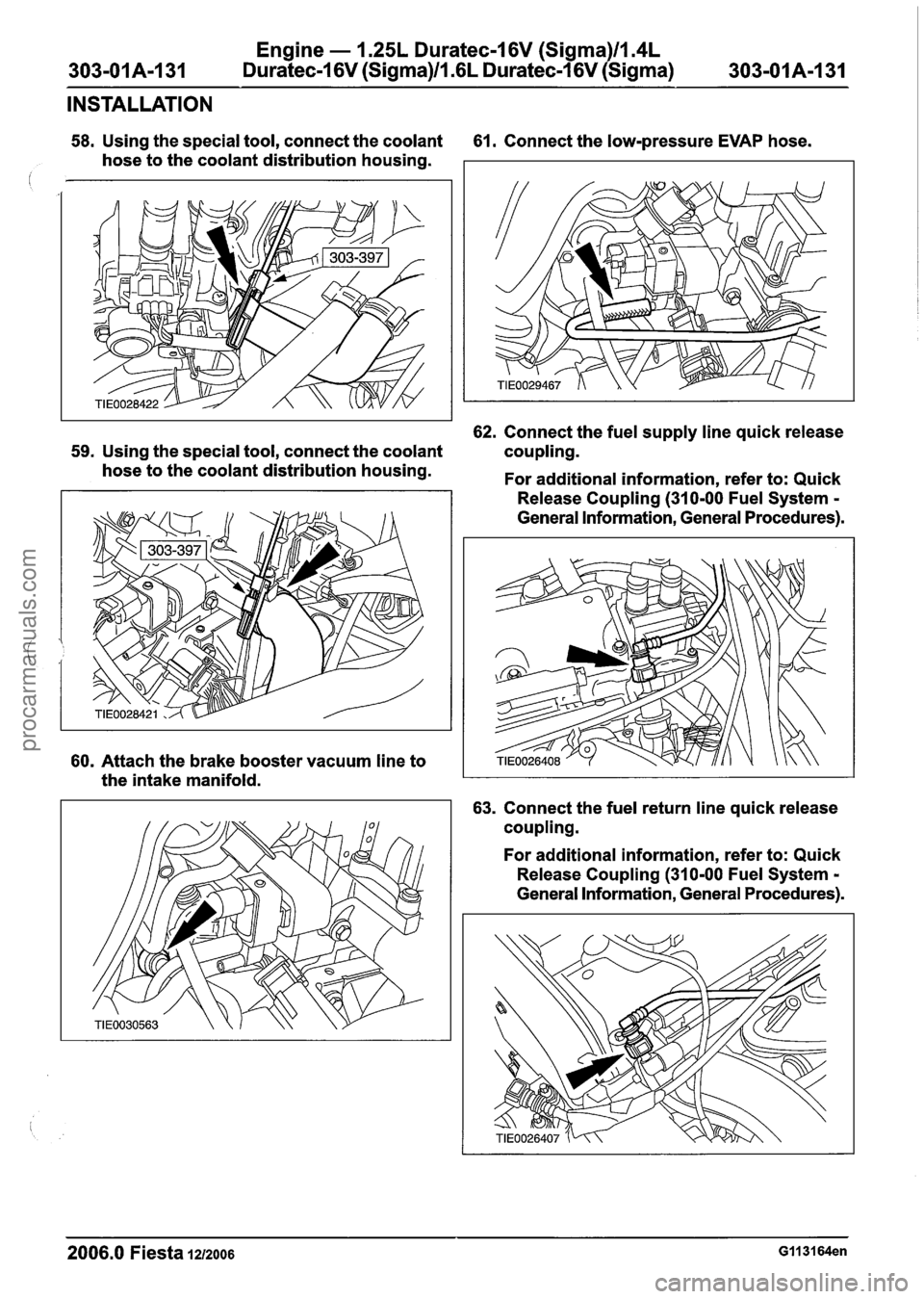
58. Using the special tool, connect the coolant 61. Connect the low-pressure EVAP hose.
hose to the coolant distribution housing.
62. Connect the fuel supply line quick release
59. Using the special tool, connect the coolant coupling.
hose to the coolant distribution housing.
For additional information, refer to: Quick
60. Attach the brake booster vacuum line to
the intake manifold. Release
Coupling (310-00 Fuel System
-
General Information, General Procedures).
63. Connect the fuel return line quick release
coupling.
For additional information, refer to: Quick
Release Coupling (310-00 Fuel System
-
General Information, General Procedures).
2006.0 Fiesta 1212006 GII 3164en
procarmanuals.com
Page 608 of 1226
Engine - I .25L Duratec-1 6V (Sigma)ll.4L
303-01 A-1 32 Duratec-1 6V (Sigma)ll .6L
Duratec-1 6V (Sigma) 303-01 A-1 32
INSTALLATION
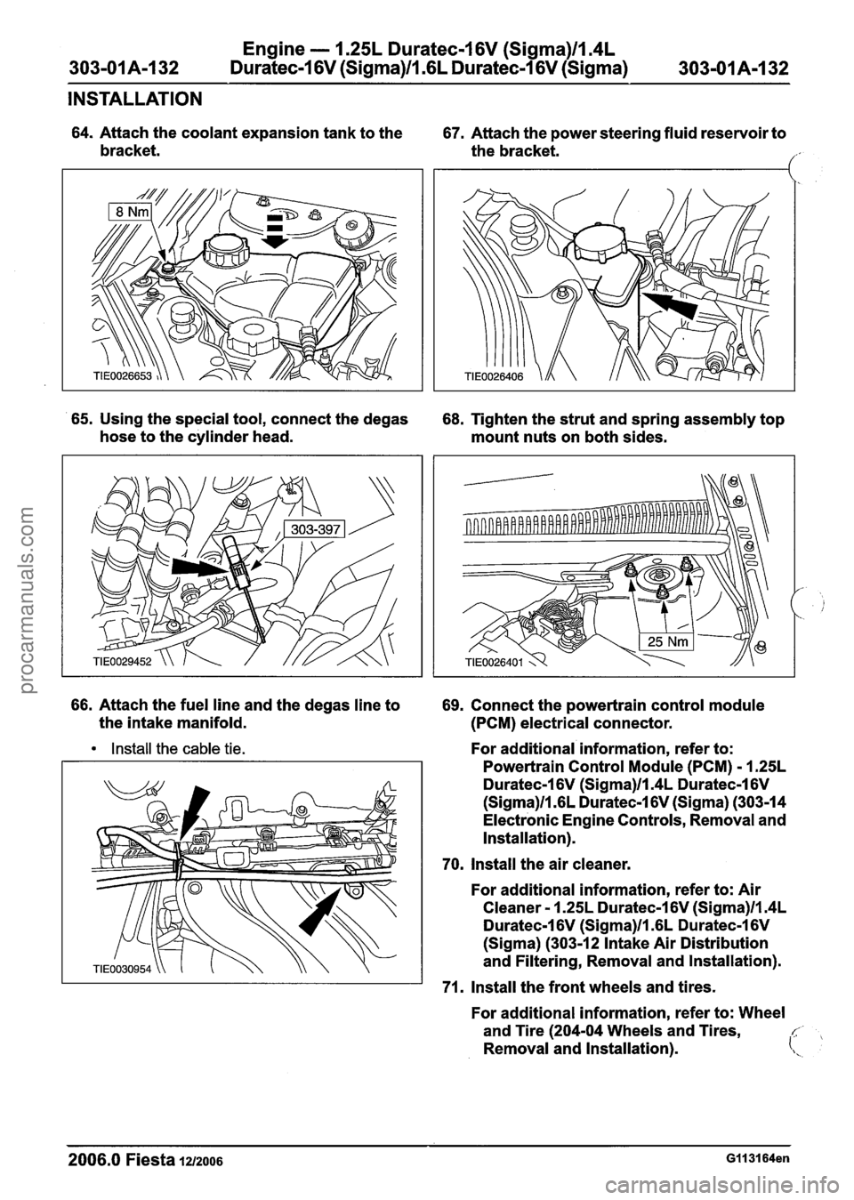
64. Attach the coolant expansion tank to the
67. Attach the power steering fluid reservoir to
bracket. the bracket.
1'
65. Using the special tool, connect the degas
68. Tighten the strut and spring assembly top
hose to the cylinder head.
mount nuts on both sides.
66. Attach the fuel line and the degas line to
69. Connect the powertrain control module
the intake manifold.
(PCM) electrical connector.
Install the cable tie. For additional information, refer to:
Powertrain Control Module (PCM)
- 1.25L
Duratec-1 6V (Sigma)ll.4L Duratec-1 6V
(Sigma)ll .6L Duratec-1 6V (Sigma) (303-14
Electronic Engine Controls, Removal and
Installation).
70. Install the air cleaner.
For additional information, refer to: Air
Cleaner
- 1.25L Duratec-1 6V (Sigma)ll.4L
Duratec-1 6V (Sigma)ll .6L Duratec-1 6V
(Sigma) (303-12 Intake Air Distribution
and Filtering, Removal and Installation).
71. Install the front wheels and tires.
For additional information, refer to: Wheel
and Tire (204-04 Wheels and Tires,
c,
Removal and Installation). (\,
2006.0 Fiesta 121zo06 GII 31 64en
procarmanuals.com
Page 613 of 1226
Engine - 1.25L Duratec-I 6V (Sigma)ll.4L
Duratec-1 6V (Sigma)/l .6L Duratec-1 6V (Sigma)
303-01 A-1 37
INSTALLATION
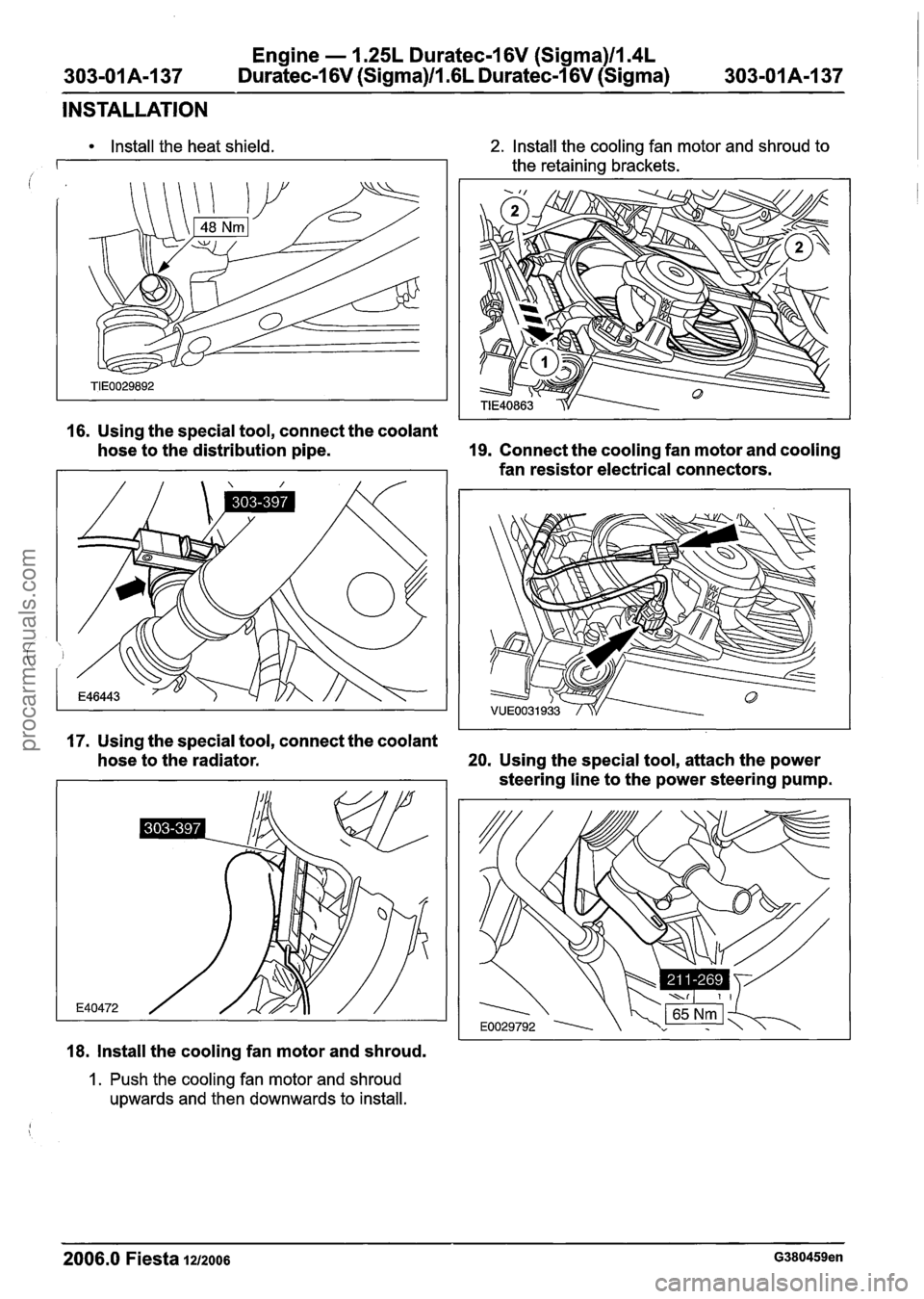
Install the heat shield. 2. Install the cooling fan motor and shroud to
the retaining brackets.
16. Using the special tool, connect the coolant
hose to the distribution pipe.
19. Connect the cooling fan motor and cooling
fan resistor electrical connectors.
17. Using the special tool, connect the coolant
hose to the radiator.
20. Using the special tool, attach the power
steering line to the power steering pump.
18. Install the cooling fan motor and shroud.
1. Push the cooling fan motor and shroud
upwards and then downwards to install.
2006.0 Fiesta 1212006 G380459en
procarmanuals.com
Page 618 of 1226
Engine - 1.25L Duratec-1 6V (Sigma)ll.4L
303-01A-I42 Duratec-1 6V (Sigma)/l .6L Duratec-I 6V (Sigma)
INSTALLATION
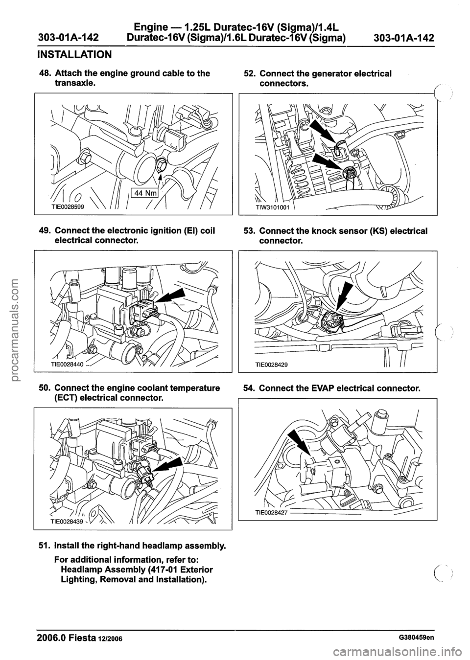
48. Attach the engine ground cable to the
transaxle. 52.
Connect the generator electrical
connectors.
49. Connect the electronic ignition (El) coil
53. Connect the knock sensor
(KS) electrical
electrical connector. connector.
50. Connect the engine coolant temperature
54. Connect the EVAP electrical connector.
(ECT) electrical connector.
51. Install the right-hand
headlamp assembly.
For additional information, refer to:
Headlamp Assembly (41 7-01 Exterior
Lighting, Removal and Installation).
2006.0 Fiesta 1212006 G380459en
procarmanuals.com
Page 619 of 1226
Engine - 1.25L Duratec-1 6V (Sigma)ll.4L
303-01 A-1 43 Duratec-1 6V (Sigma)/l.GL Duratec-1 6V (Sigma) 303-01 A-I
43
INSTALLATION
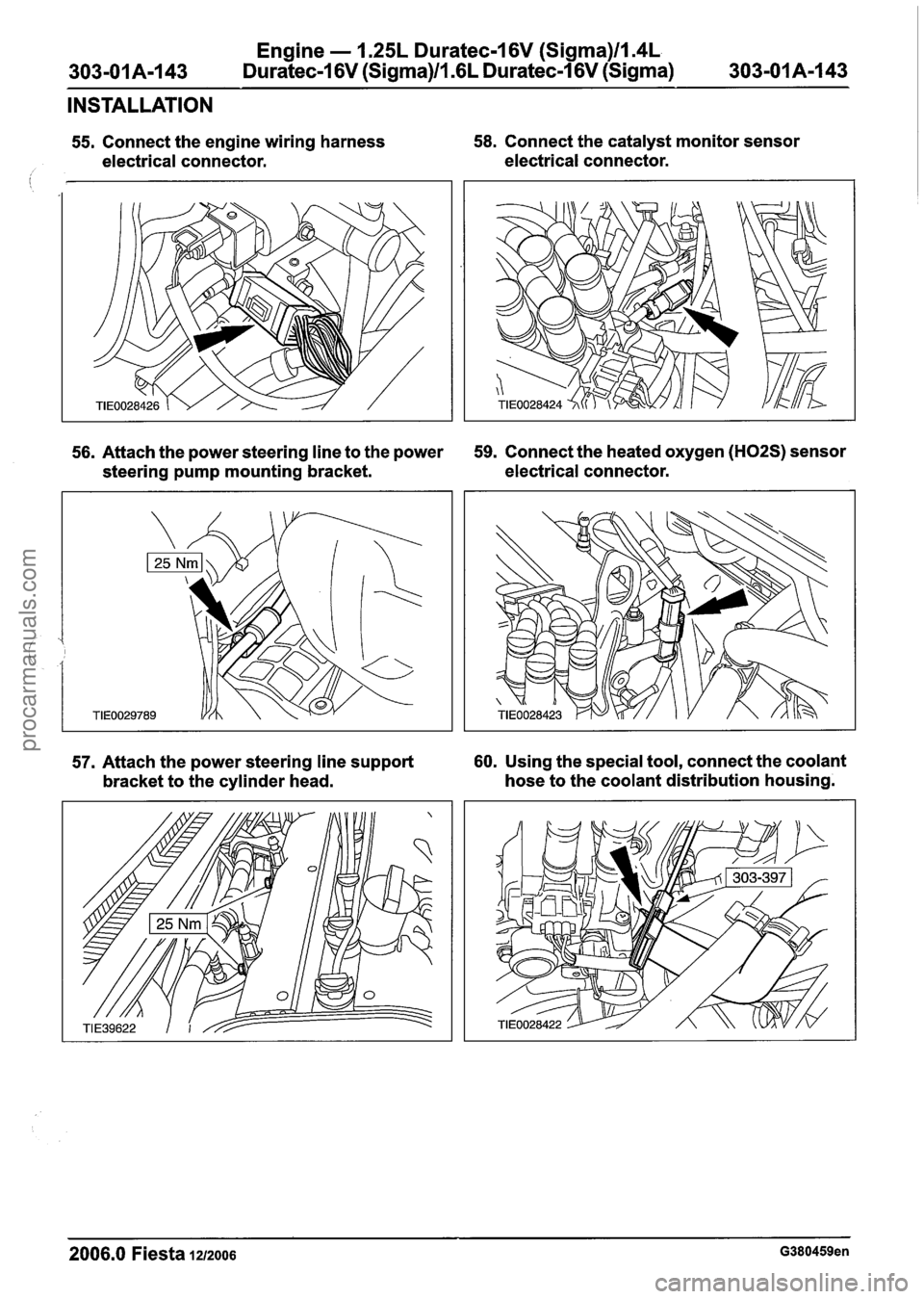
55. Connect the engine wiring harness 58. Connect the catalyst monitor sensor
electrical connector. electrical connector.
i
56. Attach the power steering line to the power 59. Connect the heated oxygen (H02S) sensor
steering pump mounting bracket. electrical
connector.
57. Attach the power steering line support 60. Using the special tool, connect the coolant
bracket to the cylinder head. hose
to the coolant distribution housing.
2006.0 Fiesta 1212006 G380459en
procarmanuals.com
Page 620 of 1226
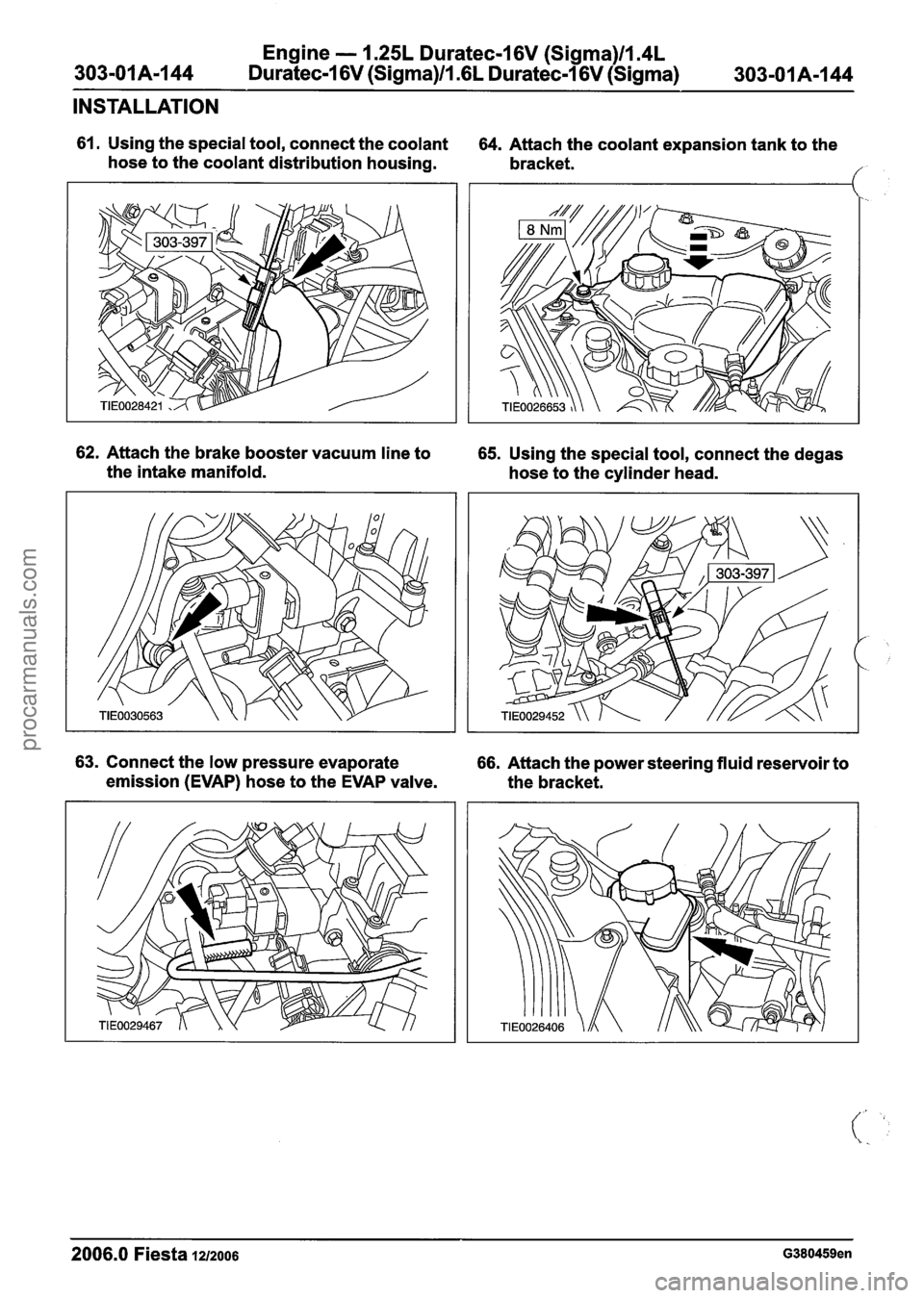
Engine - 1.25L Duratec-1 6V (Sigma)ll.4L
303-01 A-I 44 Duratec-I 6V (Sigma)ll .6L Duratec-1 6V (Sigma) 303-01 A-1 44
INSTALLATION
61. Using the special tool, connect the coolant
hose to the coolant distribution housing. 64. Attach the coolant expansion tank to the
bracket.
/
62. Attach the brake booster vacuum line to 65. Using the special tool, connect the degas
the intake manifold.
hose to the cylinder head.
63. Connect the low pressure evaporate 66. Attach the power steering fluid reservoir to
emission (EVAP) hose to the EVAP valve.
the bracket.
2006.0 Fiesta 12/2006 G380459en
procarmanuals.com