head FORD FIESTA 2007 Service Manual
[x] Cancel search | Manufacturer: FORD, Model Year: 2007, Model line: FIESTA, Model: FORD FIESTA 2007Pages: 1226, PDF Size: 61.26 MB
Page 492 of 1226
Engine - 1.25L Duratec-1 6V (Sigma)ll.4L
303-OIA-I 6 Duratec-1 6V (Sigma)ll .6L Duratec-1 6V (Sigma) 303-OIA-I 6
IN-VEHICLE REPAIR
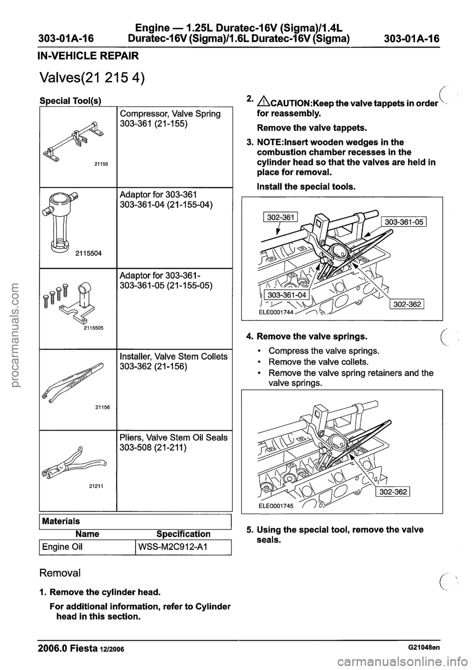
Special Tool(s1
Compressor, Valve Spring
303-36 1 (2 1
-1 55)
Adaptor for 303-361
303-36 1 -04 (2 1 -1 55-04)
I I Adaptor for 303-361 - I
4. Remove the valve springs.
Materials Name Specification
I Engine Oil I WSS-M2C912A1 I
*' ~CAUTION:K~~~ the valve tappets in order\-
for reassembly.
Remove the valve tappets.
3. N0TE:lnset-t wooden wedges in the
combustion chamber recesses in the
cylinder head so that the valves are held in
place for removal.
Install the special tools.
I I Installer, Valve Stem Collets I
I I Pliers, Valve Stem Oil Seals I
Removal
1. Remove the cylinder head.
For additional information, refer to Cylinder
head in this section.
Compress the valve springs.
Remove the valve collets.
Remove the valve spring retainers and the
valve springs.
5. Using the special tool, remove the valve
seals.
2006.0 Fiesta 1212006 G21048en
procarmanuals.com
Page 493 of 1226
Engine - 1.25L Duratec-1 6V (Sigma)ll.4L
-01A-17 Duratec-1 6V (Sigma)/l.GL Duratec-1 6V (Sigma) 303-OIA-1 7
IN-VEHICLE REPAIR
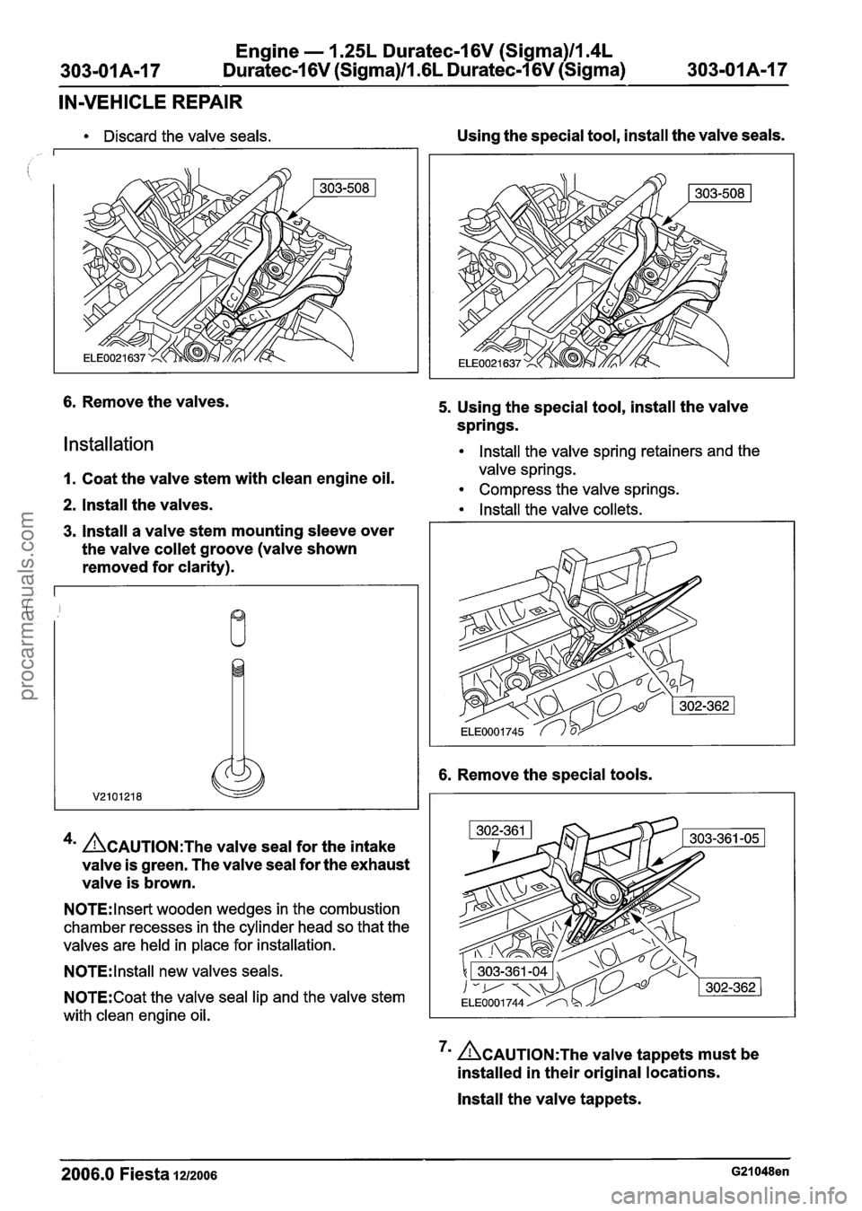
Discard the valve seals.
6. Remove the valves.
Installation
Using the special tool, install the valve seals.
5. Using the special tool, install the valve
springs.
lnstall the valve spring retainers and the
1. Coat the valve stem with clean engine oil. valve springs.
Compress the valve springs.
2. Install the valves. Install the valve collets.
3. lnstall a valve stem mounting sleeve over
the valve
collet groove (valve shown
removed for clarity).
4m ~AUTION:T~~ valve seal for the intake
valve is green. The valve seal for the exhaust
valve is brown.
N0TE:lnset-t wooden wedges in the combustion
chamber recesses in the cylinder head so that the
valves are held in place for installation.
N0TE:lnstall new valves seals.
N0TE:Coat the valve seal lip and the valve stem
with clean engine oil.
6. Remove the special tools.
7m &AUTION:T~~ valve tappets must be
installed in their original locations.
lnstall the valve tappets.
2006.0 Fiesta 1212006 G21048en
procarmanuals.com
Page 494 of 1226
Engine - 1.25L Duratec-1 6V (Sigma)ll.4L
303-01 A-I 8 Duratec-16V (Sigma)ll .6L Duratec-1 6V (Sigma) 303-01 A-I 8 - - -
IN-VEHICLE REPAIR
8. Install the cylinder head.
For additional information, refer to Cylinder
head in this section.
2006.0 Fiesta 1212006 G21048en
procarmanuals.com
Page 506 of 1226
Engine - 1.25L Duratec-1 6V (Sigma)ll.4L
Duratec-1 6V (Sigma)ll.GL Duratec-1 6V (Sigma)
IN-VEHICLE REPAIR
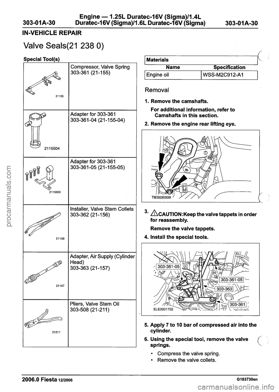
Valve Seals(21 238 0)
Special Tool(s)
I I Compressor, Valve Spring I
I I Adapter for 303-361
Installer, Valve Stem Collets
303-362 (2
1 - 1 56)
Adapter, Air Supply (Cylinder
Head)
303-363
(2 I -1 57)
Pliers, Valve Stem Oil
303-508 (21 -21
1 )
I Engine oil I WSS-M2C912A1 I
Materials
Removal
\\.
1. Remove the camshafts.
Name
Specification
For additional information, refer to
Camshafts in this section.
2. Remove the engine rear lifting eye.
3m ~CAUTION:K~~~ the valve tappets in order
for reassembly.
Remove the valve tappets.
4. Install the special tools.
5. Apply 7 to 10 bar of compressed air into the
cylinder.
1
6. Using the special tool, remove the valve
springs.
Compress the valve spring.
Remove the valve collets.
2006.0 Fiesta 1212006 GI 83730en
procarmanuals.com
Page 509 of 1226
Engine - 1.25L Duratec-1 6V (Sigma)ll.4L
303-01 A-33 Duratec-1 6V (Sigma)ll.GL Duratec-1 6V (Sigma) 303-01 A-33
IN-VEHICLE REPAIR
Camshafts(21 284 0)
Special Tool(s)
Materials
Name Specification
/ 15030A
21 171
1 Sealant I WSK-M2G348-A2 I
Universal Flange Holding
Wrench
205-072
Installer, Crankshaft Seal
303-395
I Engine Oil I WSS-M2C912A1 I
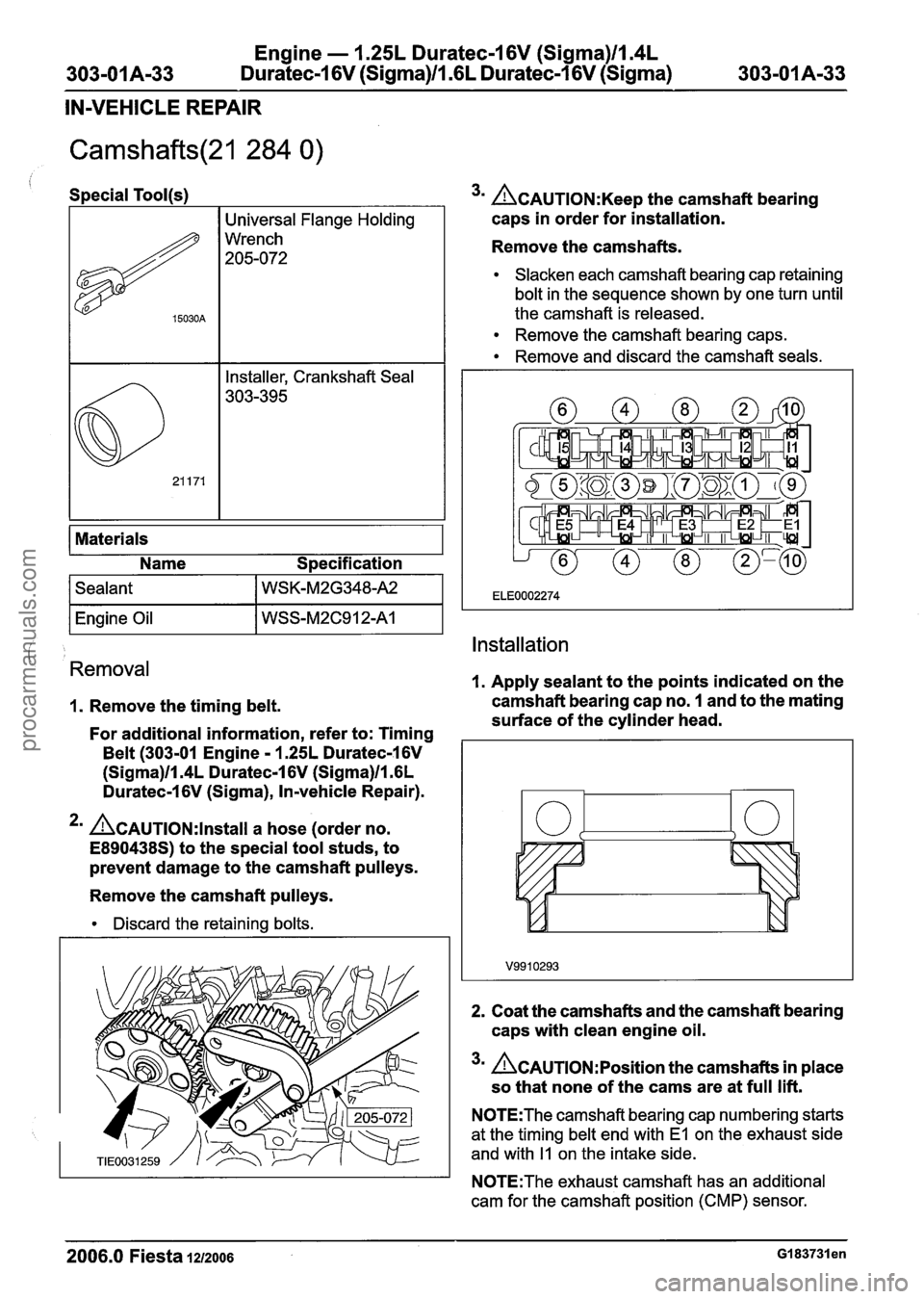
3m ~AUTION:K~~~ the camshaft bearing
caps in order for
installation.
Remove the camshafts.
Slacken each camshaft bearing cap retaining
bolt in the sequence shown by one turn until
the camshaft is released.
Remove the camshaft bearing caps.
Remove and discard the camshaft
seals.
I
i Installation
Removal
1. Apply sealant to the points indicated on the
I. Remove the timing belt. camshaft bearing
cap no. 1 and to the mating
surface of the
cylinder head.
For additional information, refer to: Timing
Belt (303-01 Engine - 1.25L Duratec-1 6V
(Sigma)ll.4L Duratec-1 6V (Sigma)ll.GL
Duratec-1 6V (Sigma), In-vehicle Repair).
2m ~~~~~10N:lnstall a hose (order no.
E890438S) to the special tool studs, to
prevent damage to the camshaft
pulleys.
Remove the camshaft pulleys.
Discard the retaining bolts.
2. Coat the camshafts and the camshaft bearing
caps with
clean engine oil.
3m A~A~T10N:~osition the camshafts in place
so that none of the cams are at full lift.
N0TE:The camshaft bearing cap numbering starts
at the timing
belt end with El on the exhaust side
and with
I1 on the intake side.
N0TE:The exhaust camshaft has an additional
cam for the camshaft position (CMP) sensor.
2006.0 Fiesta 1212006 GI 83731 en
procarmanuals.com
Page 510 of 1226
Engine - 1.25L Duratec-16V (Sigma)llI4L
303-01 A-34 Duratec-1 6V (Sigma)ll .6L
Duratec-1 6V (Sigma)
303-01 A-34
IN-VEHICLE REPAIR
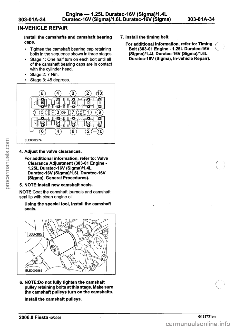
Install the camshafts and camshaft bearing 7. Install the timing belt.
caps.
For additional information, refer to: Timing
Tighten the camshaft bearing cap retaining Belt (303-01 Engine - 1.25L Duratec-1 6V
bolts in the sequence shown in three stages. (Sigma)ll.4L Duratec-1 6V (Sigma)ll .6L
Stage 1: One half turn on each bolt until all Duratec-1 6V (Sigma), Invehicle Repair).
of the camshaft bearing caps are in contact
with the cylinder head.
Stage
2: 7 Nm.
Stage
3: 45 degrees.
4. Adjust the valve clearances.
For additional information, refer to: Valve
Clearance Adjustment (303-01 Engine -
1.25L Duratec-1 6V (Sigma)ll.4L
, Duratec-1 6V (Sigma)ll .6L Duratec-1 6V
(Sigma), General Procedures).
5. NOTE:
Install new camshaft seals.
N0TE:Coat the camshaft journals and camshaft
seal lip with clean engine oil.
Using the special tool, install the camshaft
seals.
6. N0TE:Do not fully tighten the camshaft
pulley retaining bolts at this stage. Make sure
the camshaft
pulleys turn on the camshafts.
Install the camshaft pulleys.
2006.0 Fiesta 1212006 GI 83731 en
procarmanuals.com
Page 524 of 1226
Engine - 1.25L Duratec-1 6V (Sigma)ll.4L
303-01 A-48 Duratec-1 6V (Sigma)/l .6L Duratec-1 6V (Sigma)
303-01 A-48
IN-VEHICLE REPAIR
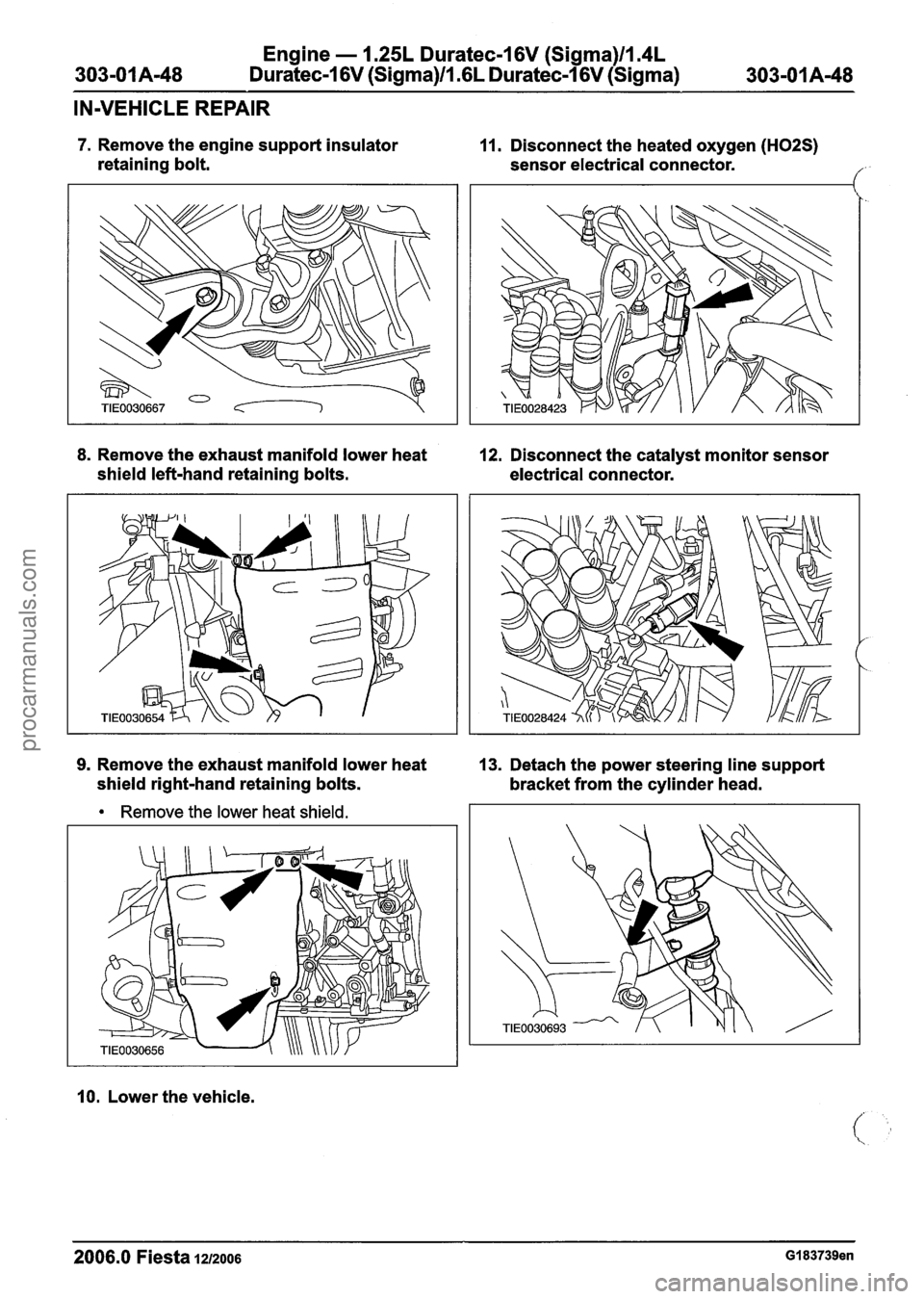
7. Remove the engine support insulator
retaining bolt.
8. Remove the exhaust manifold lower heat
shield left-hand retaining bolts. 11.
Disconnect the heated oxygen
(H02S)
sensor electrical connector. //' '
12. Disconnect the catalyst monitor sensor
electrical connector.
9. Remove the exhaust manifold lower heat
13. Detach the power steering line support
shield right-hand retaining bolts.
bracket from the cylinder head.
Remove the lower heat shield.
10. Lower the vehicle.
2006.0 Fiesta 1212006 GI 83739en
procarmanuals.com
Page 526 of 1226
Engine - 1.25L Duratec-I 6V (Sigma)llm4L
303-01 A-50 Duratec-1 6V (Sigma)ll .6L Duratec-1 6V (Sigma)
303-01 A-50
IN-VEHICLE REPAIR
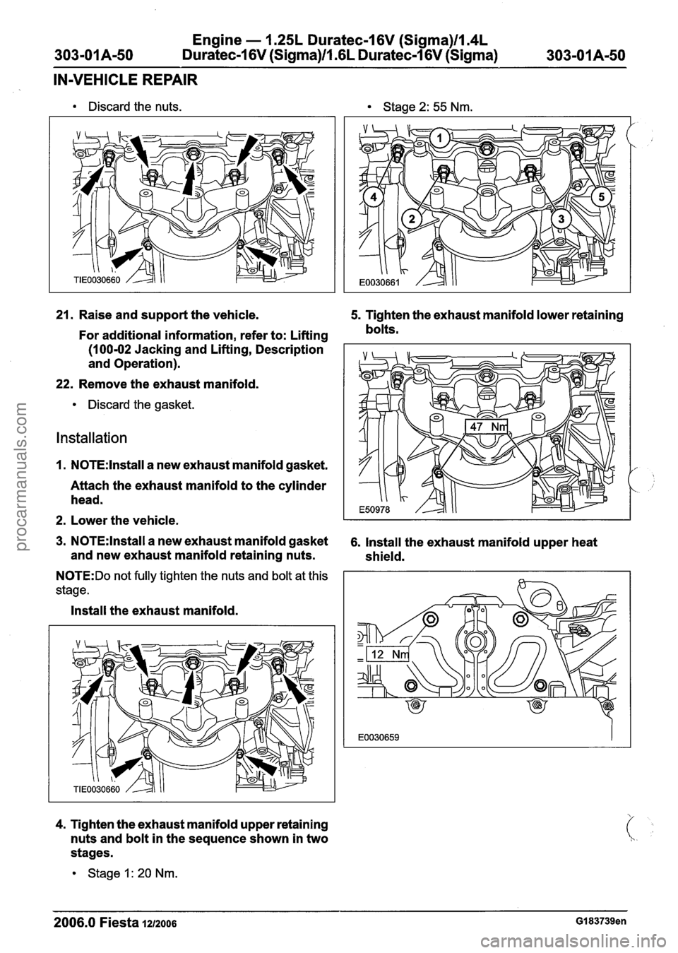
Discard the nuts. Stage 2: 55 Nm.
21. Raise and support the vehicle. 5. Tighten the exhaust manifold lower retaining
For additional information, refer to: Lifting bolts.
(1 00-02 Jacking and
Lifting, Description
and Operation).
22. Remove the exhaust manifold.
Discard the gasket.
Installation
1. N0TE:lnstall a new exhaust manifold gasket.
Attach the exhaust manifold to the cylinder
head.
2. Lower the vehicle.
3. N0TE:lnstall a new exhaust manifold gasket 6. Install the exhaust manifold upper heat
and new exhaust manifold retaining nuts.
shield.
N0TE:Do not fully tighten the nuts and bolt at this
stage.
Install the exhaust manifold.
4. Tighten the exhaust manifold upper retaining
nuts and bolt in the sequence shown in two
stages.
Stage 1 : 20 Nm.
2006.0 Fiesta 1212006 GI 83739en
procarmanuals.com
Page 527 of 1226

Engine - 1.25L Duratec-1 6V (Sigma)ll14L
Duratec-1 6V (Sigma)/l .6L Duratec-1 6V (Sigma)
IN-VEHICLE REPAIR
7. Using the special tools, raise the engine. 10. Attach the coolant expansion tank to the
bracket.
,
8. N0TE:lnstall new engine front mount
retaining nuts.
11. Attach the power steering fluid reservoir to
Install the engine front mount. the
bracket.
9. Remove the special tools. 12. Attach the power steering line bracket to
the cylinder head.
2006.0 Fiesta 1212006 GI 83739en
procarmanuals.com
Page 530 of 1226
Engine - I .25L Duratec-1 6V (Sigma)llI4L
303-01 A-54 Duratec-1 6V (Sigma)/l .6L Duratec-1 6V (Sigma)
303-01 A-54
IN-VEHICLE REPAIR
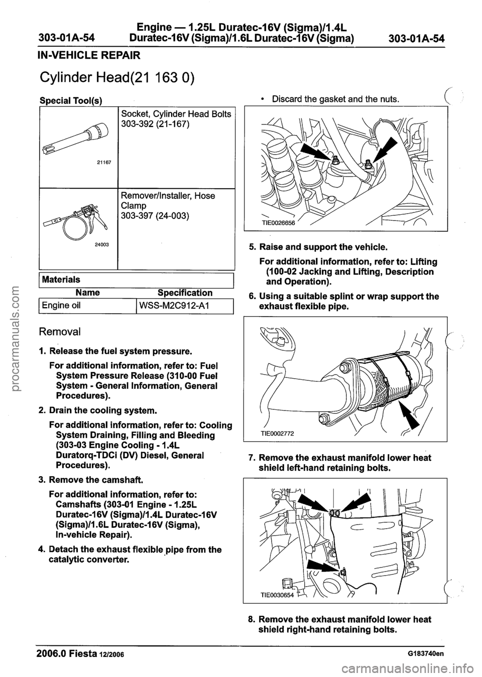
Cylinder Head(21 163 0)
1 I Socket, Cylinder Head Bolts I
Discard the gasket and the nuts. (
Removerllnstaller, Hose
Clamp
303-397 (24-003)
I 24003 1 1 5. Raise and support the vehicle.
Removal
I I 1 For additional information, refer to: Lifting
(100-02 Jacking and Lifting, Description
1. Release the fuel system pressure.
Materials
For
additional information, refer to: Fuel
System Pressure Release (31 0-00 Fuel
System - General Information, General
Procedures). and
Operation).
2. Drain the
cooling system.
For
additional information, refer to: Cooling
System Draining, Filling and Bleeding
(303-03 Engine Cooling - 1.4L
Duratorq-TDCi (DV) Diesel, General 7. Remove the exhaust manifold lower heat
Procedures). shield left-hand retaining bolts.
3. Remove the camshaft.
Name
Specification
6. Using a suitable splint or wrap support the
For
additional information, refer to:
Camshafts
(303-01 Engine - 1.25L
Duratec-1 6V (Sigma)ll.4L Duratec-1 6V
(Sigma)ll.GL Duratec-1 6V (Sigma),
In-vehicle Repair).
Engine oil I WSS-M2C912-A1
4. Detach the exhaust flexible pipe from the
catalytic converter. exhaust
flexible pipe.
8. Remove the exhaust manifold lower heat
shield right-hand retaining bolts.
2006.0 Fiesta 1212006 GI 83740en
procarmanuals.com