sensor FORD FIESTA 2007 Manual Online
[x] Cancel search | Manufacturer: FORD, Model Year: 2007, Model line: FIESTA, Model: FORD FIESTA 2007Pages: 1226, PDF Size: 61.26 MB
Page 614 of 1226
Engine - 1.25L Duratec-1 6V (Sigma)ll.4L
Duratec-1 6V (Sigma)ll .6L Duratec-1 6V (Sigma)
303-01 A-1 38
INSTALLATION
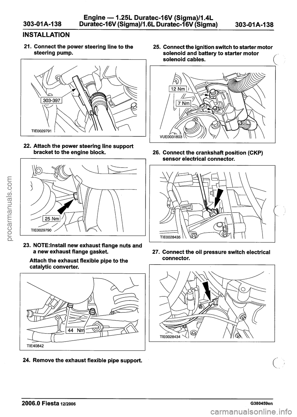
21. Connect the power steering line to the 25. Connect the ignition switch to starter motor
steering pump.
solenoid and battery to starter motor
solenoid cables.
22. Attach the power steering line support
bracket to the engine block.
26. Connect the crankshaft position (CKP)
sensor electrical connector.
23. N0TE:lnstall new exhaust flange nuts and
a new exhaust flange gasket.
27. Connect the oil pressure switch electrical
Attach the exhaust flexible pipe to the connector.
catalytic converter.
24. Remove the exhaust flexible pipe support.
2006.0 Fiesta 1212006 G380459en
procarmanuals.com
Page 616 of 1226
Engine - 1.25L Duratec-1 6V (Sigma)ll.4L
303-01 A-1 40 Duratec-1 6V (Sigma)ll .6L
Duratec-1 6V (Sigma) 303-01 A-1 40
INSTALLATION
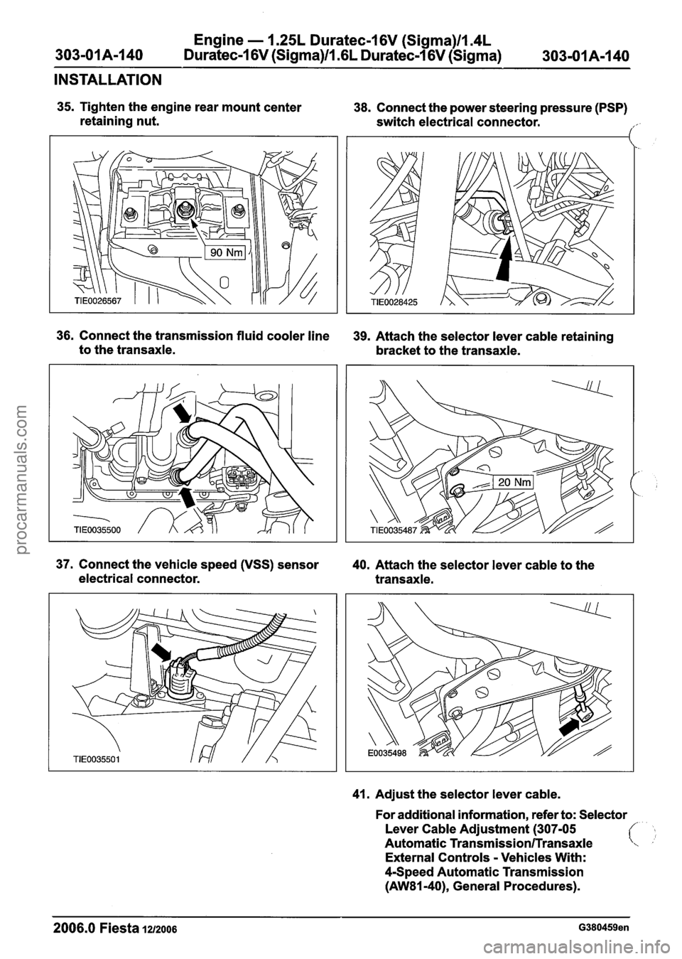
35. Tighten the engine rear mount center
retaining nut. 38. Connect the power steering pressure (PSP)
switch electrical connector.
,/'
36. Connect the transmission fluid cooler line 39. Attach the selector lever cable retaining
to the transaxle.
bracket to the transaxle.
37. Connect the vehicle speed (VSS) sensor
40. Attach the selector lever cable to the
electrical connector. transaxle.
41. Adjust the selector lever cable.
For additional information, refer to: Selector
Lever Cable Adjustment (307-05
Automatic
Transmission/Transaxle
External Controls - Vehicles With:
4-Speed Automatic Transmission
(AW81-40), General Procedures).
2006.0 Fiesta 1212006 G380459en
procarmanuals.com
Page 617 of 1226
Engine - 1.25L Duratec-1 6V (Sigma)ll.4L
Duratec-1 6V (Sigma)ll .6L Duratec-1 6V (Sigma) 303-01 A-1 41
INSTALLATION
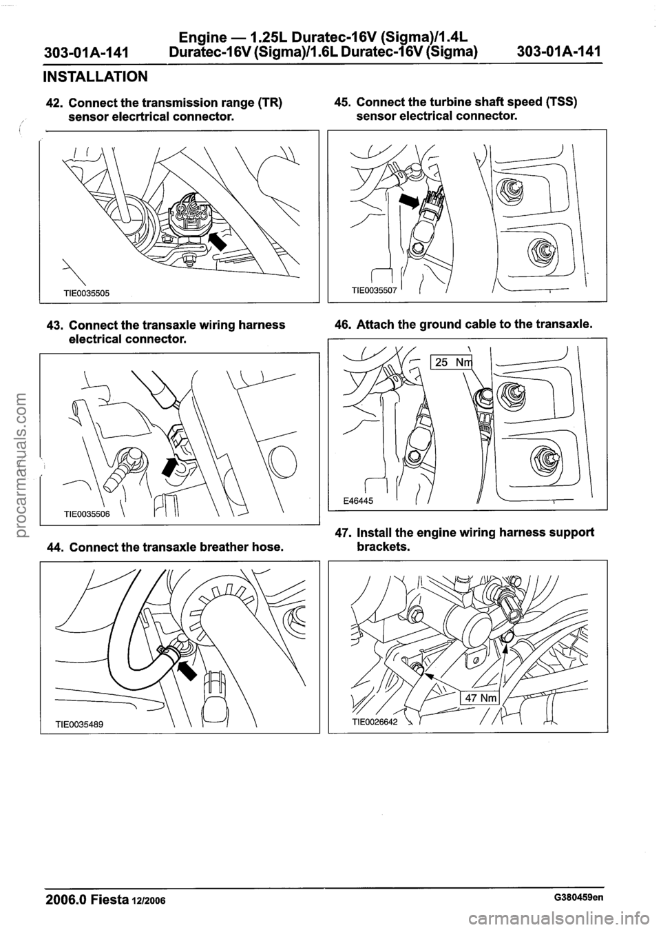
42. Connect the transmission range (TR) 45. Connect the turbine shaft speed (TSS)
I sensor elecrtrical connector. sensor electrical connector.
43. Connect the transaxle wiring harness
46. Attach the ground cable to the transaxle.
electrical connector.
47. Install the engine wiring harness support
44. Connect the transaxle breather hose. brackets.
2006.0 Fiesta 1212006 G380459en
procarmanuals.com
Page 618 of 1226
Engine - 1.25L Duratec-1 6V (Sigma)ll.4L
303-01A-I42 Duratec-1 6V (Sigma)/l .6L Duratec-I 6V (Sigma)
INSTALLATION
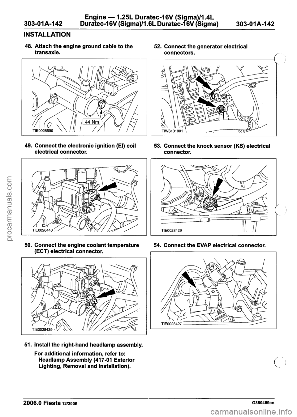
48. Attach the engine ground cable to the
transaxle. 52.
Connect the generator electrical
connectors.
49. Connect the electronic ignition (El) coil
53. Connect the knock sensor
(KS) electrical
electrical connector. connector.
50. Connect the engine coolant temperature
54. Connect the EVAP electrical connector.
(ECT) electrical connector.
51. Install the right-hand
headlamp assembly.
For additional information, refer to:
Headlamp Assembly (41 7-01 Exterior
Lighting, Removal and Installation).
2006.0 Fiesta 1212006 G380459en
procarmanuals.com
Page 619 of 1226
Engine - 1.25L Duratec-1 6V (Sigma)ll.4L
303-01 A-1 43 Duratec-1 6V (Sigma)/l.GL Duratec-1 6V (Sigma) 303-01 A-I
43
INSTALLATION
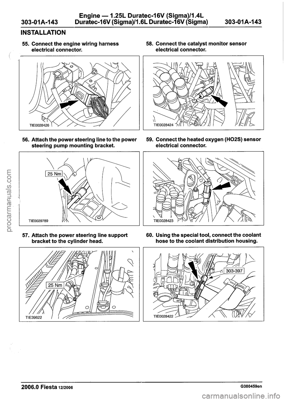
55. Connect the engine wiring harness 58. Connect the catalyst monitor sensor
electrical connector. electrical connector.
i
56. Attach the power steering line to the power 59. Connect the heated oxygen (H02S) sensor
steering pump mounting bracket. electrical
connector.
57. Attach the power steering line support 60. Using the special tool, connect the coolant
bracket to the cylinder head. hose
to the coolant distribution housing.
2006.0 Fiesta 1212006 G380459en
procarmanuals.com
Page 627 of 1226
303-01 B-5 Engine - 2.OL Duratec-HE (M14) 303-01 B-5
SPECIFICATIONS
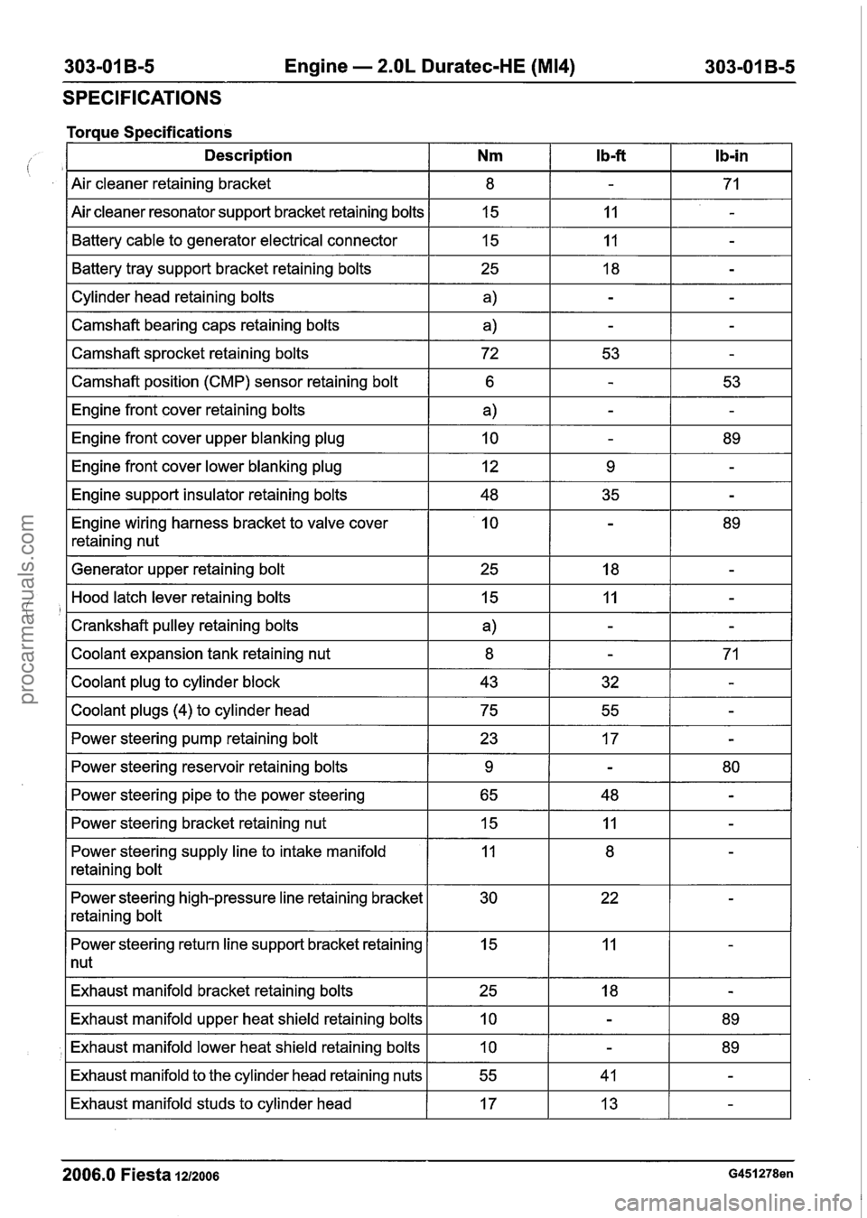
Torque Specifications - --- -- - -- -
Description Nm l b-ft Ib-in
Air cleaner retaining bracket
Air cleaner resonator support bracket retaining bolts Battery cable to generator electrical connector
I Cylinder head retaining bolts I a) I - I - I
Battery tray support bracket retaining bolts
I
--
I Camshaft bearing caps retaining bolts a) IT
15
15
I Camshaft sprocket retaining bolts I 72 I 53 I - I
25
I Camshaft position (CMP) sensor retaining bolt I 6 1 - I 53 I
11
I1
-
-
18
I Engine front cover lower blanking plug I 12 I 9 I - I
-
Engine front cover retaining bolts
Engine front cover upper blanking plug
I Engine support insulator retaining bolts I 48 I 35 I - I
Engine wiring harness bracket to valve cover
retaining nut
a)
10
I Generator upper retaining bolt I 25 I 18 I - I
-
-
I Coolant plugs (4) to cylinder head I 75 I 55 I - I
-
89
Hood latch lever retaining bolts
Crankshaft pulley retaining bolts
Coolant expansion tank retaining nut
Coolant plug to cylinder block
I Power steering pump retaining bolt I 23 I 17 I - I
15
a)
8
43
I
--
I Power steering bracket retaining nut 15 IT
Power steering reservoir retaining bolts
Power steering pipe to the power steering
Power steering supply line to intake manifold
retaining bolt
11
-
-
32
Power steering high-pressure line retaining bracket
retaining bolt
-
-
71
-
9
65
I Power steering return line support bracket retaining I 15 I 11 I - I
1 nut
-
48 80 -
Exhaust
manifold bracket retaining bolts
2006.0 Fiesta 1212006 G451278en
Exhaust manifold upper heat shield retaining bolts
Exhaust manifold lower heat shield retaining bolts
Exhaust manifold to the cylinder head retaining nuts
Exhaust manifold studs to cylinder head
25
10
10
55
17 18
-
-
-
41
13 89
89 -
-
procarmanuals.com
Page 628 of 1226
,303-01 B-6 Engine - 2.OL Duratec-HE (M14) 303-01 B-6
SPECIFICATIONS
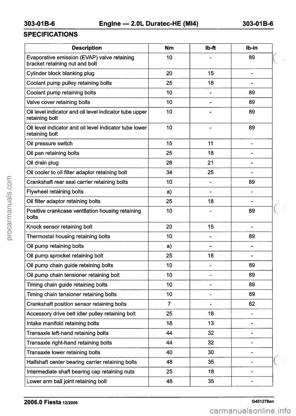
I Description I Nm' I Ib-ft I Ib-in I
Evaporative emission (EVAP) valve retaining
bracket retaining nut and bolt
Valve cover retaining bolts
I 10 I - I 89 I
Cylinder block blanking plug
Coolant pump pulley retaining bolts
Coolant pump retaining bolts
Oil level indicator and oil level indicator tube upper
retaining bolt
Oil level indicator and oil level indicator tube lower
retaining bolt 20
25
10
Oil pressure switch I 15 I 11 I - I
I Oil pan retaining bolts
15
18
-
-
-
89
I Crankshaft rear seal carrier retaining bolts I 10 I - I 89 I
Oil drain plug
Oil cooler to oil filter adaptor retaining bolt
I Flywheel retaining bolts I a) I - I - I
28
34
I Knock sensor retaining bolt I 20 I 15 I - I
Oil filter adaptor retaining bolts
Positive crankcase ventilation housing retaining
bolts
I Thermostat housing retaining bolts I 10 I - I 89 I
21
25
I Oil pump retaining bolts I a) I - I - I
-
-
25
10
I Oil pump sprocket retaining bolt I 25 I 18 I - I
18
-
-
89
Oil pump chain guide retaining bolts
Oil pump chain tensioner retaining bolt
I Crankshaft position sensor retaining bolts I 7 I - I 62 I
Timing chain guide retaining bolts
Timing chain tensioner retaining bolts
I Accessory drive belt idler pulley retaining bolt I 25 I 18 I - I
10
10
I Intake manifold retaining bolts I 18 I 13 I - I
10
10
I Transaxle left-hand retaining bolts I 44 I 32 I - I
-
-
I Transaxle right-hand retaining bolts I 44 I 32 I - I
89
89
-
-
89
89
Transaxle lower retaining bolts
Halfshaft center bearing carrier retaining bolts
I Lower arm ball joint retaining bolt I 48 I 35 I - I
Intermediate shaft bearing cap retaining nuts
2006.0 Fiesta 1212006 G451278en
40
48
25 30
35 -
-
18 -
procarmanuals.com
Page 638 of 1226
303-01 B-I 6 Engine - 2.OL Duratec-HE (M14) 303-01 B-I 6
GENERAL PROCEDURES
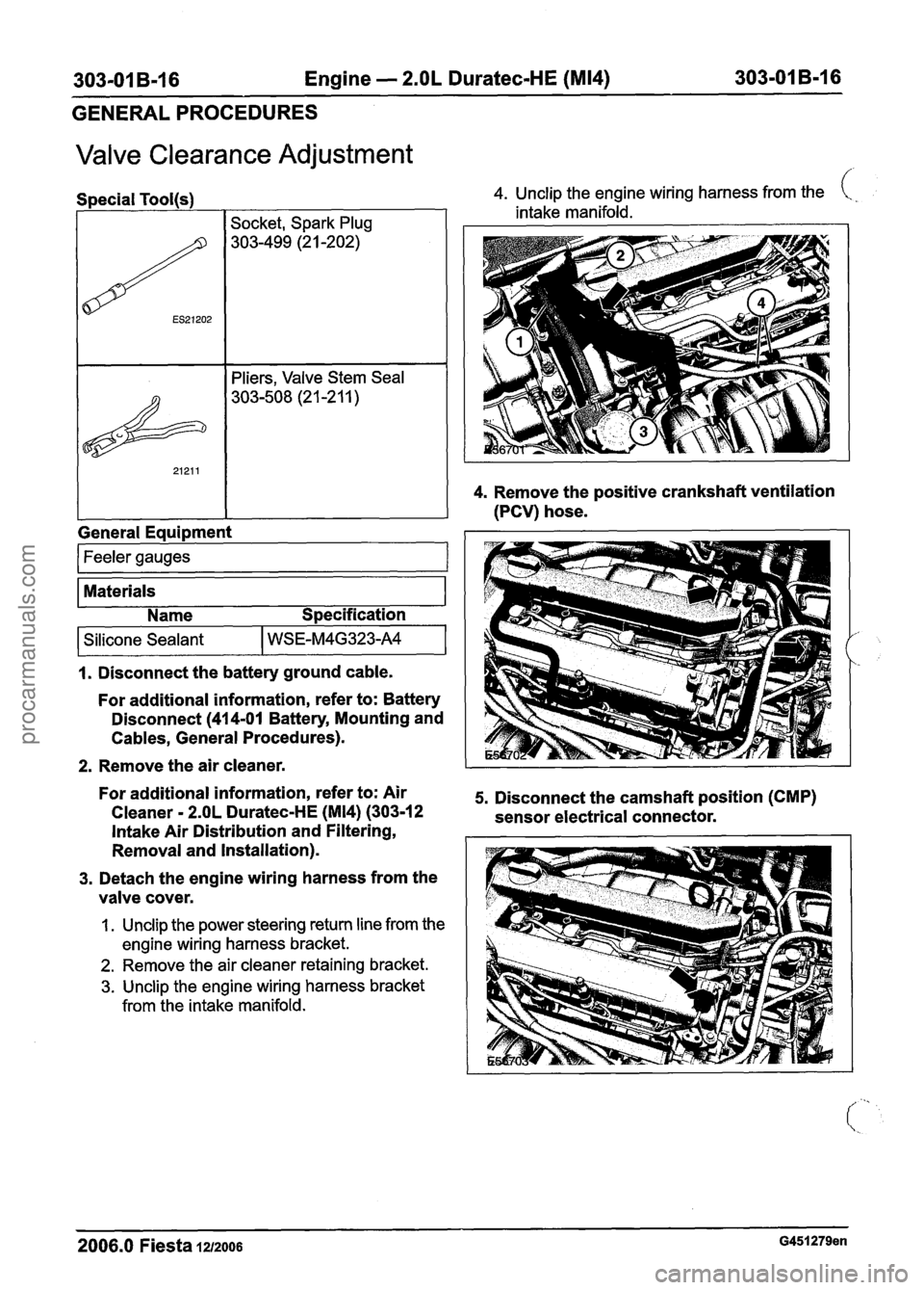
Valve Clearance Adjustment
Feeler gauges 1
Materials
Special
Tool(s) 4.
Unclip the engine wiring harness from the i..
I I
Name Specification
intake manifold.
4. Remove the positive crankshaft ventilation
(PCV) hose.
/ ES21202
&
21211
1. Disconnect the battery ground cable.
General
Equipment
i
Socket, Spark Plug
303-499 (2
1 -202)
Pliers, Valve Stem Seal
303-508
(2 1 -2 1 1 )
- --
For additional information, refer to: Battery
Disconnect (41 4-01 Battery, Mounting and
Cables, General Procedures).
Silicone Sealant
2. Remove the air cleaner.
WSE-M4G323-A4
For additional information, refer to: Air 5. Disconnect the camshaft position (CMP)
Cleaner - 2.OL Duratec-HE (M14) (303-1 2
sensor electrical connector.
Intake Air Distribution and Filtering,
Removal and Installation).
3. Detach the engine wiring harness from the
valve cover.
1. Unclip the power steering return line from the
engine wiring harness bracket.
2. Remove the air cleaner retaining bracket.
3. Unclip the engine wiring harness bracket
from the intake manifold.
2006.0 Fiesta 1212006 G451279en
procarmanuals.com
Page 641 of 1226
303-01 B-19 Engine - 2.OL Duratec-HE (M14) 303-01 B-19
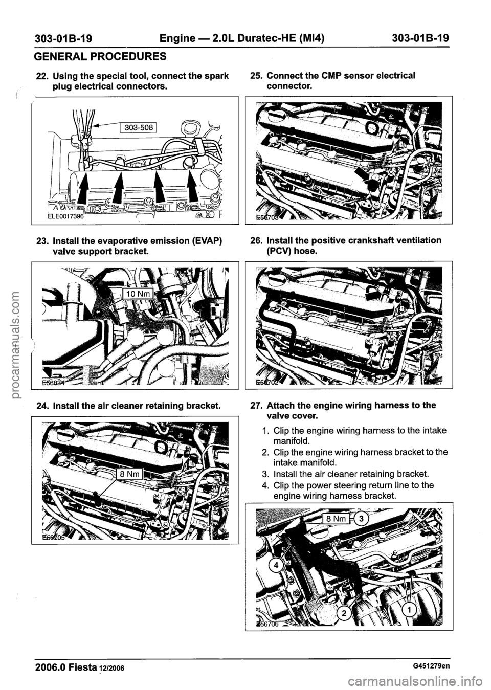
22. Using the special tool, connect the spark 25. Connect the CMP sensor electrical
plug electrical connectors. connector.
1 1
GENERAL PROCEDURES
23. Install the evaporative emission (EVAP) 26. Install the positive crankshaft ventilation
valve support bracket. (PCV) hose.
24. Install the air cleaner retaining bracket. 27. Attach the engine wiring harness to the
valve cover.
1. Clip the engine wiring harness to the intake
manifold.
2. Clip the engine wiring harness bracket to the
intake manifold.
3. Install the air cleaner retaining bracket.
4. Clip the power steering return line to the
engine wiring harness bracket.
2006.0 Fiesta 1212006 G451279en
procarmanuals.com
Page 643 of 1226
303-01 B-21 Engine - 2.OL Duratec-HE (M14) 303-01 B-21
IN-VEHICLE REPAIR
Intake Manifold(21 183 0)
Removal
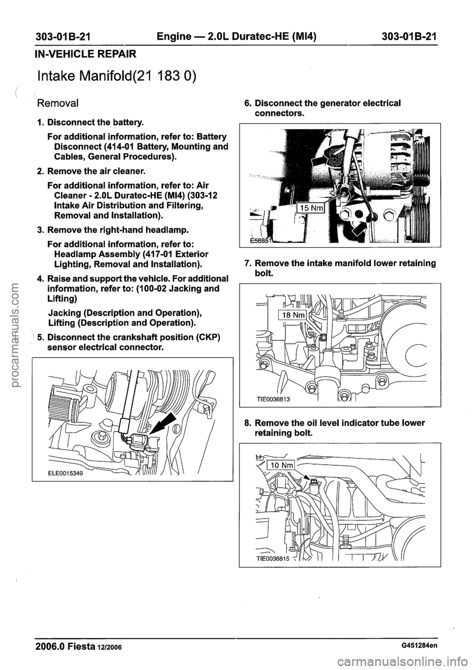
1. Disconnect the battery.
For additional information, refer to: Battery
Disconnect (414-01 Battery, Mounting and
Cables, General Procedures).
2. Remove the air cleaner.
For additional information, refer to: Air
Cleaner
- 2.OL Duratec-HE (M14) (303-12
lntake Air Distribution and Filtering,
Removal and Installation).
3. Remove the right-hand headlamp.
6. Disconnect the generator electrical
connectors.
For additional information, refer to:
Headlamp Assembly (41 7-01 Exterior
Lighting, Removal and Installation). 7.
Remove the intake manifold lower retaining
4. Raise and support the vehicle. For additional bolt.
information, refer to: (I
00-02 Jacking and
Lifting)
Jacking (Description and Operation),
Lifting (Description and Operation).
( 5. Disconnect the crankshaft position (CKP)
sensor electrical connector.
8. Remove the oil level indicator tube lower
retaining bolt.
2006.0 Fiesta 1212006 G451284en
procarmanuals.com