FORD FIESTA 2007 Workshop Manual
Manufacturer: FORD, Model Year: 2007, Model line: FIESTA, Model: FORD FIESTA 2007Pages: 1226, PDF Size: 61.26 MB
Page 661 of 1226
303-01 B-39 Engine - 2.OL Duratec-HE (M14) 303-01 B-39
IN-VEHICLE REPAIR
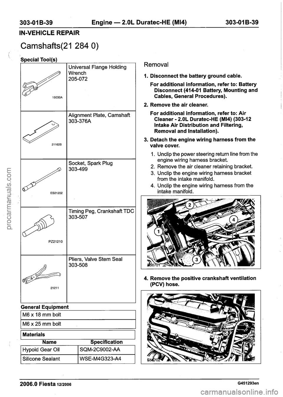
Special Tool(s)
I I Universal Flange Holding I
General Equipment
15030A
1~6 x 18 mm bolt I
Wrench
205-072
Materials
Name Specification
Removal
Hypoid Gear Oil
Silicone Sealant
1. Disconnect the battery ground cable.
SQM-2C9002-AA
WSE-M4G323-A4
For additional information, refer to: Battery
Disconnect
(414-01 Battery, Mounting and
Cables, General Procedures).
2. Remove the air cleaner.
For additional information, refer to: Air
Cleaner
- 2.OL Duratec-HE (M14) (303-12
Intake Air Distribution and Filtering,
Removal and Installation).
3. Detach the engine wiring harness from the
valve cover.
1. Unclip the power steering return line from the
engine wiring harness bracket.
2. Remove the air cleaner retaining bracket.
3. Unclip the engine wiring harness bracket
from the intake manifold.
4. Unclip the engine wiring harness from the
intake manifold.
4. Remove the positive crankshaft ventilation
(PCV) hose.
2006.0 Fiesta 1212006 G451293en
procarmanuals.com
Page 662 of 1226
303-01 B-40 Engine - 2.OL Duratec-HE (M14) 303-01 B-40
IN-VEHICLE
REPAIR
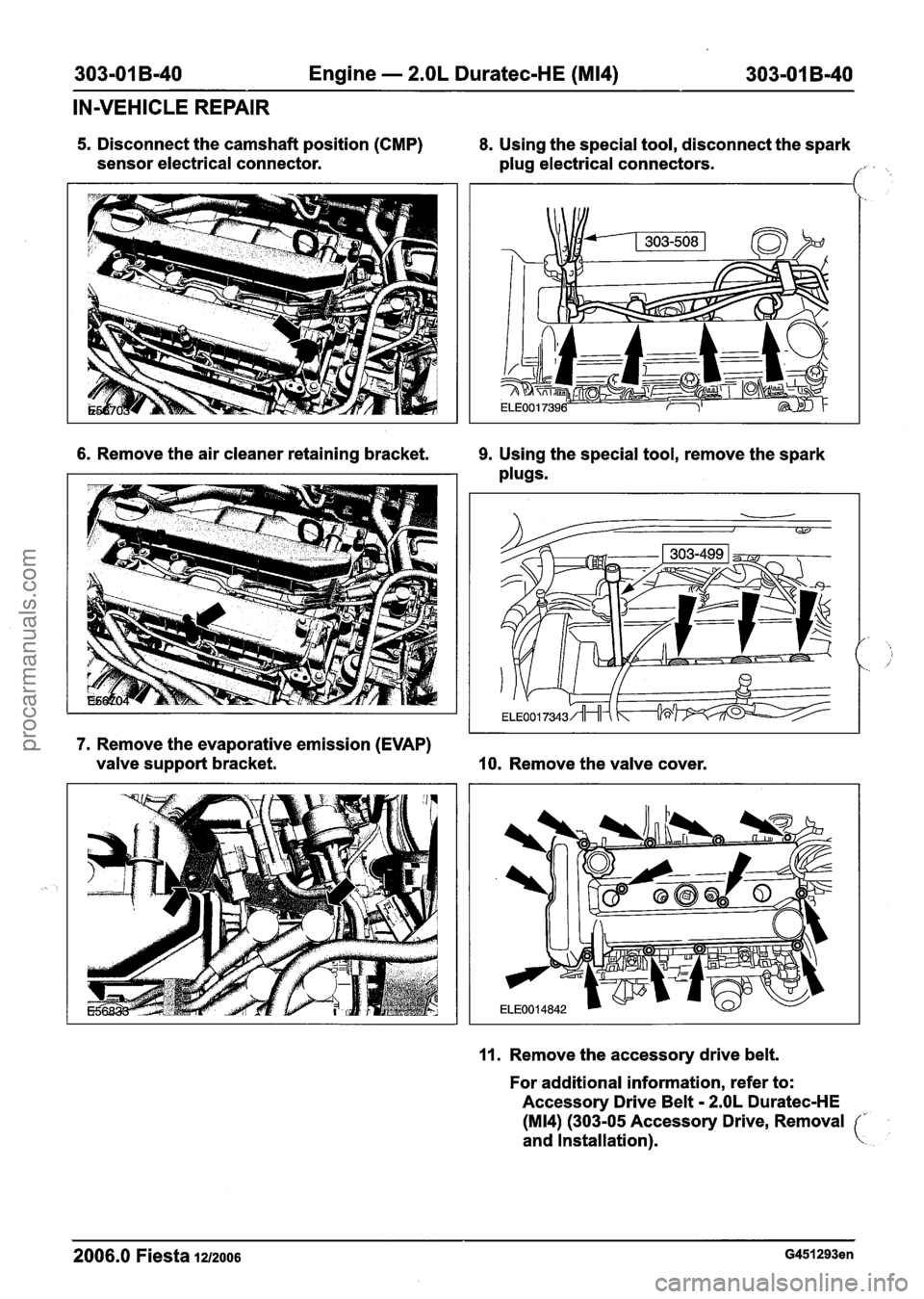
5. Disconnect the camshaft position (CMP) 8. Using the special tool, disconnect the spark
sensor electrical connector.
plug electrical connectors.
1.
6. Remove the air cleaner retaining bracket. 9. Using the special tool, remove the spark
plugs.
7. Remove the evaporative emission (EVAP)
valve support bracket.
10. Remove the valve cover.
11. Remove the accessory drive belt.
For additional information, refer to:
Accessory Drive Belt
- 2.OL Duratec-HE
(M14) (303-05 Accessory Drive, Removal
and Installation).
c
2006.0 Fiesta la2006 G451293en
procarmanuals.com
Page 663 of 1226
303-01 B-41 Engine - 2.OL Duratec-HE (M14) 303-01 B-41
IN-VEHICLE REPAIR
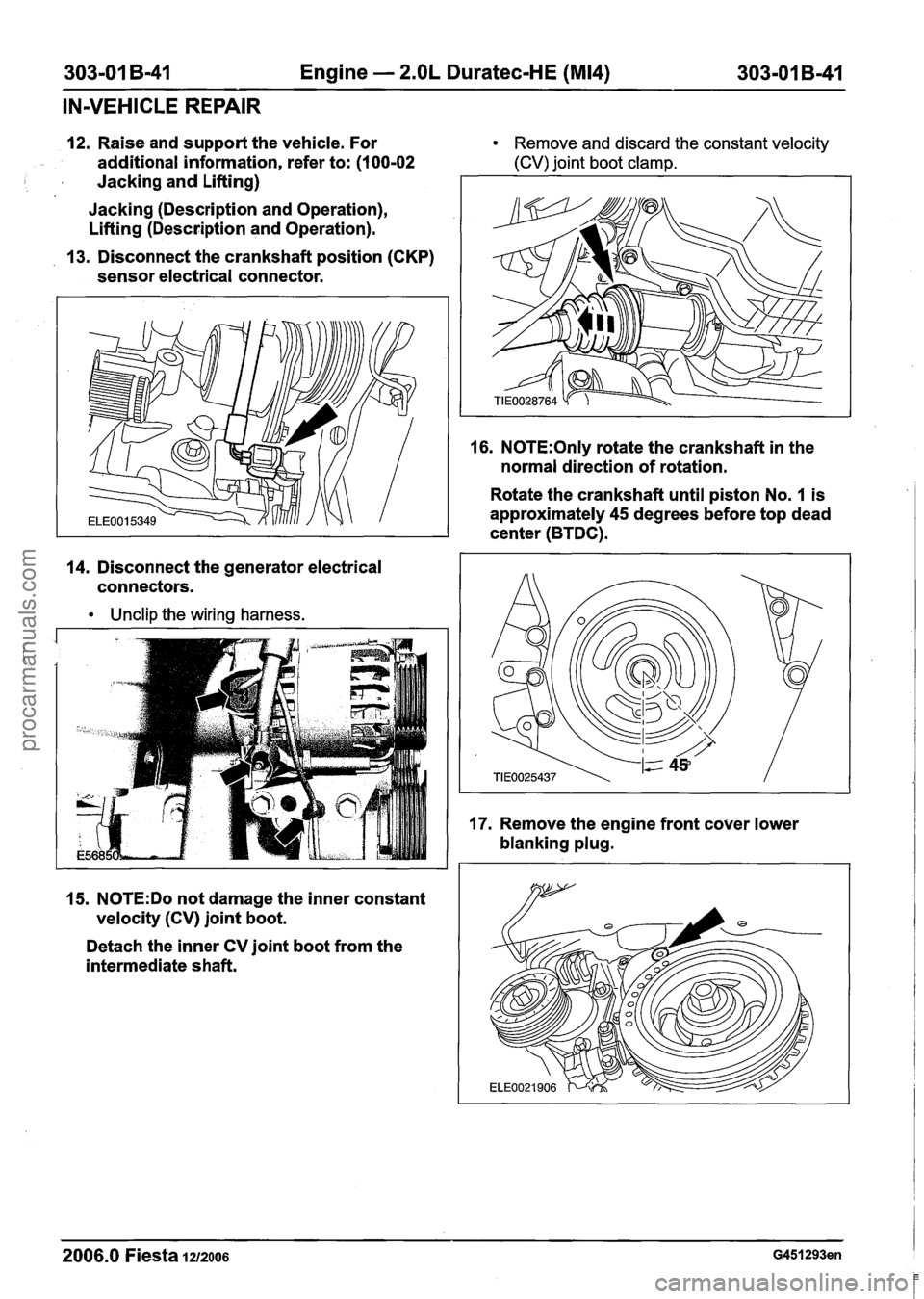
12. Raise and support the vehicle. For Remove and discard the constant velocity
additional information, refer to: (1 00-02 (CV) joint boot clamp.
I Jacking and Lifting)
Jacking (Description and Operation),
Lifting (Description and Operation).
13. Disconnect the crankshaft position (CKP)
sensor electrical connector.
14. Disconnect the generator electrical
connectors.
Unclip the wiring harness.
16. N0TE:Only rotate the crankshaft in the
normal direction of rotation.
Rotate the crankshaft until piston No.
1 is
approximately 45 degrees before top dead
center (BTDC).
15.
N0TE:Do not damage the inner constant
velocity (CV) joint boot.
Detach the inner CV joint boot from the
intermediate shaft.
2006.0 Fiesta 1212006 G451293en
procarmanuals.com
Page 664 of 1226
303-01 B-42 Engine - 2.OL Duratec-HE (M14) 303-01 B-42 -
IN-VEHICLE REPAIR
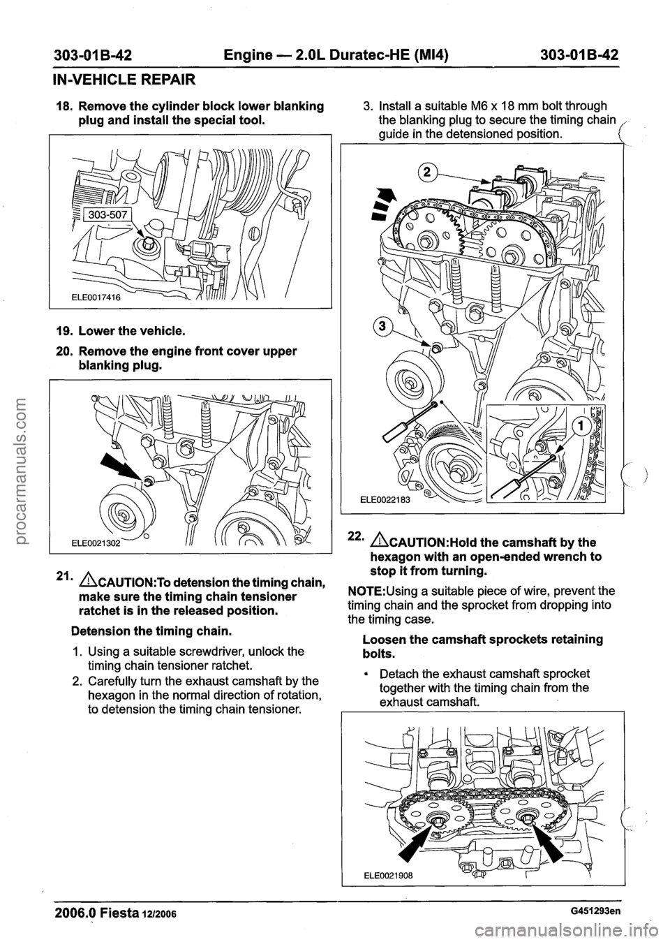
18. Remove the cylinder block lower blanking
plug and install the special tool.
19. Lower the vehicle.
20. Remove the engine front cover upper
blanking plug.
3. Install a suitable M6 x 18 mm bolt through
the blanking plug to secure the timing chain
guide in the detensioned position.
22m ACAUTION:H~I~ the camshaft by the
hexagon with an open-ended wrench to
stop it from turning.
21 ACAUTION:T~ detension the timing chain,
make sure the timing chain tensioner N0TE:Using a suitable piece of wire, prevent the
ratchet is in the released position. timing chain and the sprocket from dropping into
the timing case.
Detension the timing chain. -
Loosen the camshaft sprockets retaining
1. Using a suitable screwdriver, unlock the bolts.
timing chain tensioner ratchet.
2. Carefully turn the exhaust camshaft by the Detach the exhaust camshaft sprocket
hexagon in the normal direction of rotation, together
with the timing chain from the
exhaust camshaft.
to detension the timing chain tensioner.
2006.0 Fiesta 1212006 G451293en
procarmanuals.com
Page 665 of 1226
303-01 B-43 Engine - 2.OL Duratec-HE (M14) 303-01 B-43
IN-VEHICLE REPAIR
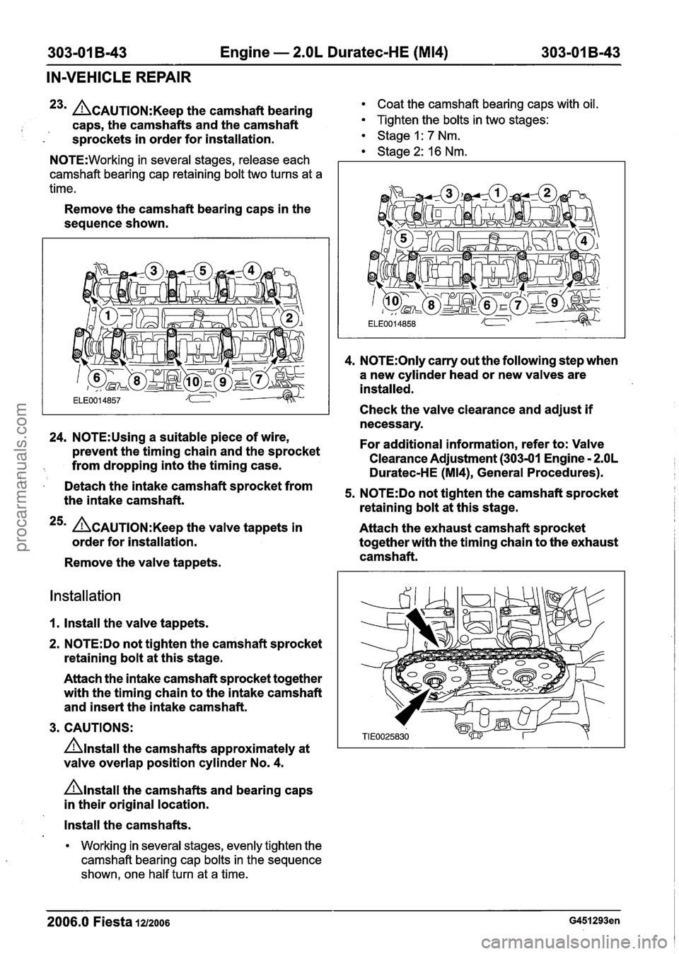
23m L?~AUTION:K~~~ the camshaft bearing Coat the camshaft bearing caps with oil.
I caps, the camshafts and the camshaft Tighten the bolts in two stages:
- s~rockets in order for installation. Stage I: 7 Nm. 1 Stage 2: 16 Nm. N0TE:Working in several stages, release each
camshaft bearing cap retaining bolt two turns at a
time.
Remove the camshaft bearing caps in the
sequence shown.
24. N0TE:Using a suitable piece of wire,
prevent the timing chain and the sprocket
from dropping into the timing case.
I Detach the intake camshaft sprocket from
the intake camshaft.
25m ACAUTION:K~~~ the valve tappets in
order for installation.
Remove the valve tappets.
Installation
1. Install the valve tappets.
2.
N0TE:Do not tighten the camshaft sprocket
retaining bolt at this stage.
Attach the intake camshaft sprocket together
with the timing chain to the intake camshaft
and insert the intake camshaft.
3. CAUTIONS:
Anstall the camshafts approximately at
valve overlap position cylinder No.
4.
nlnstall the camshafts and bearing caps
in their original location.
4. N0TE:Only carry out the following step when
a new cylinder head or new valves are
installed.
Check the valve clearance and adjust
if
necessary.
For additional information, refer to: Valve
Clearance Adjustment (303-01 Engine
- 2.OL
Duratec-HE (M14), General Procedures).
5. N0TE:Do not tighten the camshaft sprocket
retaining bolt at this stage.
Attach the exhaust camshaft sprocket
together with the timing chain to the exhaust
camshaft.
Install the camshafts.
Working in several stages, evenly tighten the
camshaft bearing cap bolts in the sequence
shown, one half turn at a time.
2006.0 Fiesta 1212006
procarmanuals.com
Page 666 of 1226
303-01 B-44 Engine - 2.OL Duratec-HE (M14) 303-01 B-44
IN-VEHICLE REPAIR
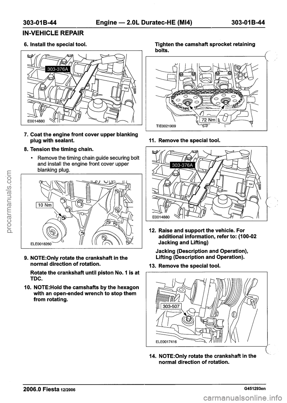
6. Install the special tool. Tighten
the camshaft sprocket retaining
bolts.
,
7. Coat the engine front cover upper blanking
plug with sealant.
11. Remove the special tool.
8. Tension the timing chain.
Remove the timing chain guide securing bolt
and install the engine front cover upper
blanking plug.
12. Raise and support the vehicle. For
additional information, refer to: (1
00-02
Jacking and Lifting) I I Jacking (Description and Operation),
9. N0TE:Only rotate the crankshaft in the Lifting
(Description and Operation).
normal direction of rotation.
13. Remove the special tool.
Rotate the crankshaft until piston No.
I is at
TDC.
10.
N0TE:Hold the camshafts by the hexagon
with an open-ended wrench to stop them
from rotating.
14.
N0TE:Only rotate the crankshaft in the <
normal direction of rotation.
2006.0 Fiesta 1212006 G451293en
procarmanuals.com
Page 667 of 1226
303-01 B-45 Engine - 2.OL Duratec-HE (M14) 303-01 B-45
IN-VEHICLE REPAIR
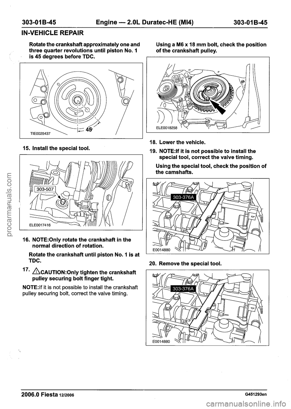
Rotate the crankshaft approximately one and
Using a M6 x 18 mm bolt, check the position
three quarter revolutions until piston No.
I of the crankshaft pulley. 1 is 45 degrees before TDC.
18. Lower the vehicle.
15. Install the special tool. 19. N0TE:lf it is not possible to install the
special tool, correct the valve timing.
Using the special tool, check the position of
the camshafts.
16. N0TE:Only rotate the crankshaft in the
normal direction of rotation.
Rotate the crankshaft until piston No.
1 is at
TDC.
20. Remove the special tool.
17' ACAUTION:O~I~ tighten the crankshaft
pulley securing bolt finger tight.
N0TE:lf it is not possible to install the crankshaft
pulley securing bolt, correct the valve timing.
2006.0 Fiesta 1212006 G451293en
procarmanuals.com
Page 668 of 1226
303-01 B-46 Engine - 2.OL Duratec-HE (M14) 303-01 B-46
IN-VEHICLE REPAIR
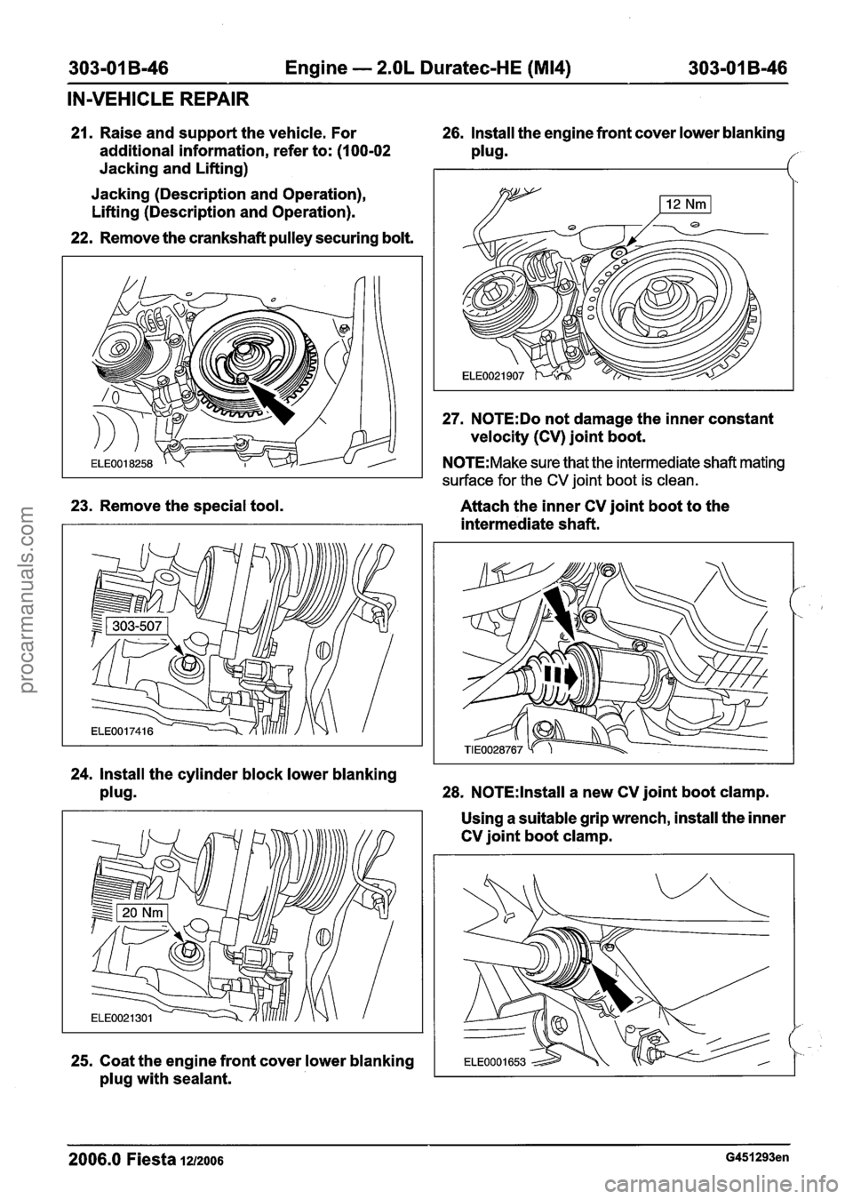
23. Remove the special tool.
21. Raise and support the vehicle. For 26. Install the engine front cover lower blanking
additional information, refer to:
(I 00-02 plug.
27. N0TE:Do not damage the inner constant
velocity (CV) joint boot.
Jacking
and Lifting)
Jacking (Description and Operation),
Lifting (Description and Operation).
22. Remove the crankshaft pulley securing bolt.
N0TE:Make sure that the intermediate shaft mating
surface for the
CV joint boot is clean.
ELE0021907
Attach the inner CV joint boot to the
intermediate shaft.
24. Install the cylinder block lower blanking
plugB 28. N0TE:lnstall a new CV joint boot clamp.
25. Coat the engine front cover lower blanking
plug with sealant. Using
a suitable grip wrench, install the inner
CV joint boot clamp.
2006.0 Fiesta 1212006 G451293en
procarmanuals.com
Page 669 of 1226
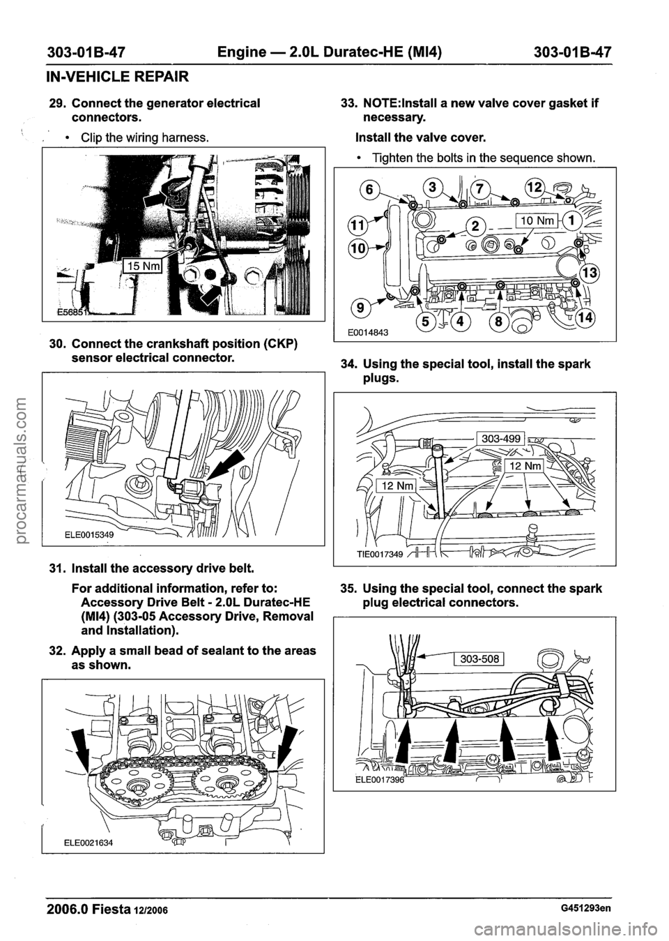
303-01 B-47 Engine - 2.OL Duratec-HE (M14) 303-01 B-47
IN-VEHICLE REPAIR
29. Connect the generator electrical
connectors.
Clip the wiring harness.
33. N0TE:lnstall a new valve cover gasket if
necessary.
Install the valve cover.
Tighten the bolts in the sequence shown.
I I
30. Connect the crankshaft position (CKP) I I
sensor electrical connector.
34. Using the special tool, install the spark
plugs.
31. Install the accessory drive belt.
For additional information, refer to:
35. Using the special tool, connect the spark
Accessory Drive Belt
- 2.OL Duratec-HE
plug electrical connectors.
(M14) (303-05 Accessory Drive, Removal
and Installation).
32. Apply a small bead of sealant to the areas
as shown.
2006.0 Fiesta 1212006 G451293en
procarmanuals.com
Page 670 of 1226
303-01 B-48 Engine - 2.OL Duratec-HE (M14) 303-01 B-48
IN-VEHICLE REPAIR
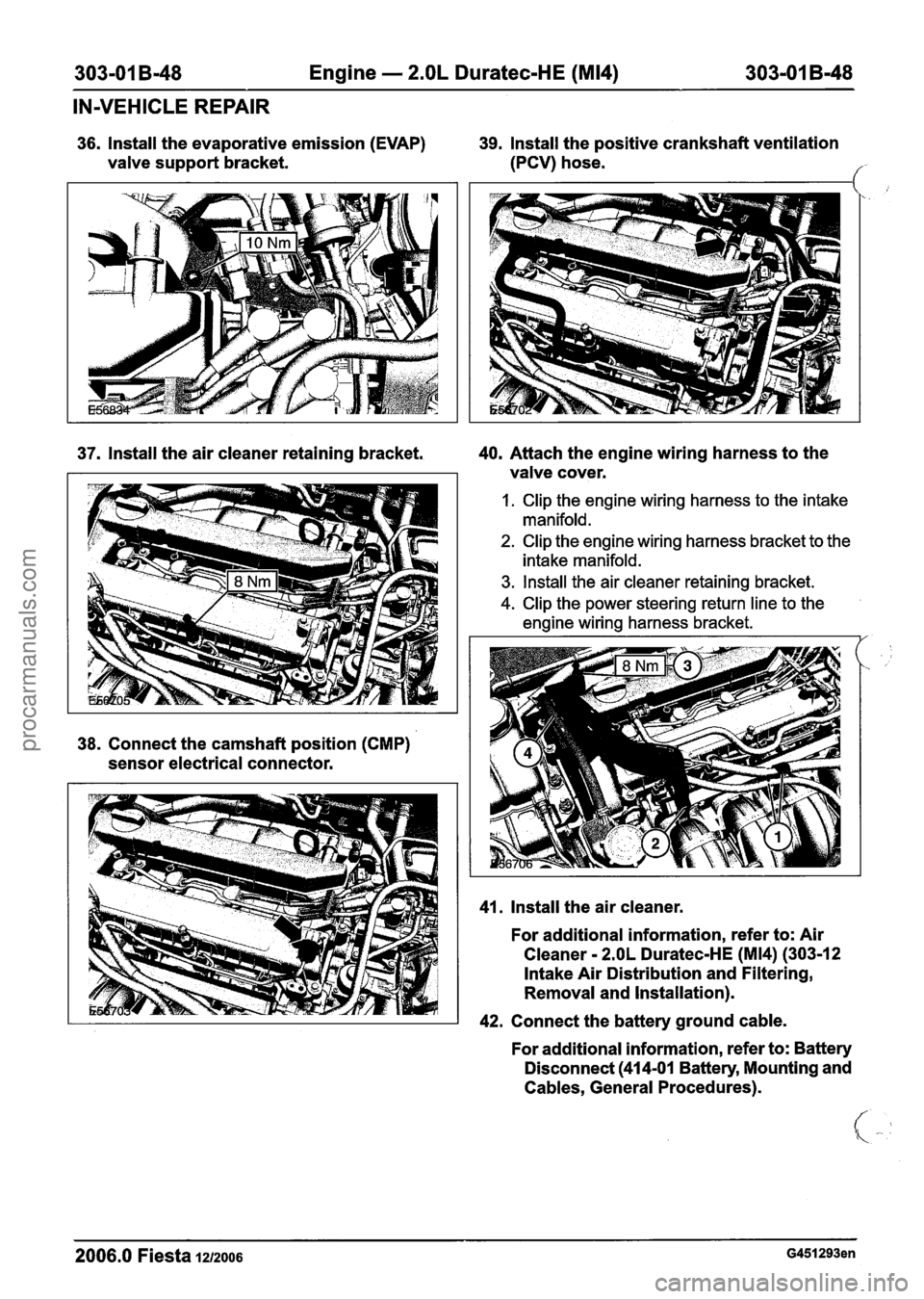
36. lnstall the evaporative emission (EVAP)
valve support bracket.
37. lnstall the air cleaner retaining bracket.
38. Connect the camshaft position (CMP)
sensor electrical connector.
39. lnstall the positive crankshaft ventilation
(PCV) hose.
f
40. Attach the engine wiring harness to the
valve cover.
I. Clip the engine wiring harness to the intake
manifold.
2. Clip the engine wiring harness bracket to the
intake manifold.
3. lnstall the air cleaner retaining bracket.
4. Clip the power steering return line to the
engine wiring harness bracket.
41. lnstall the air cleaner.
For additional information, refer to: Air
Cleaner
- 2.OL Duratec-HE (M14) (30312
Intake Air Distribution and Filtering,
Removal and Installation).
42. Connect the battery ground cable.
For additional information, refer to: Battery
Disconnect
(414-01 Battery, Mounting and
Cables, General Procedures).
2006.0 Fiesta 1212006 G451293en
procarmanuals.com