jacking FORD FIESTA 2007 Manual PDF
[x] Cancel search | Manufacturer: FORD, Model Year: 2007, Model line: FIESTA, Model: FORD FIESTA 2007Pages: 1226, PDF Size: 61.26 MB
Page 761 of 1226
Engine Cooling - 1.3L Duratec-8V
(Rocam)ll.25L Duratec-1 6V (Sigma)llI4L
303-03A-19 Duratec-1 6V (Sigma)lll6L Duratec-I 6V (Sigma) 303-03A-19
GENERAL PROCEDURES
Cooling System Draining, Filling and Bleeding - 1.3L Duratec-8V
I (Rocam)/l.25L Duratec-1 6V (Sigma)/l.4L Duratec-1 6V
(Sigma)/l.6L Duratec-1 6V (Sigma)(24 122 0)
Draining 5. Install the radiator drain plug.
la AWARNING:~~~~ releasing the cooling 6. Lower the vehicle.
system pressure, cover the coolant
expansion tank cap with a thick cloth to
Filling and Bleeding
prevent the possibility of scalding. Failure 1. Remove the radiator bleed plug (if equipped). to follow this instruction may result in
personal injury.
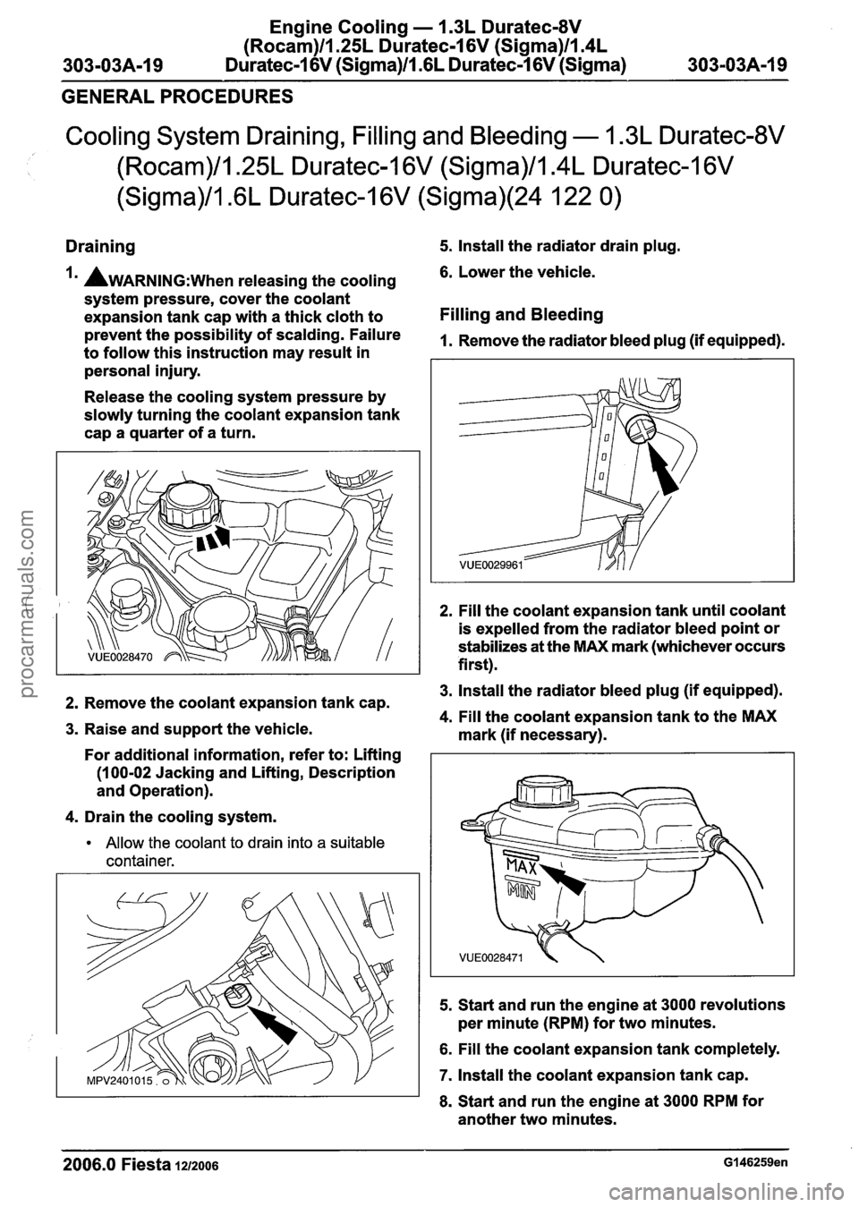
Release the cooling system pressure by
slowly turning the coolant expansion tank
cap a quarter of a turn.
2. Fill the coolant expansion tank until coolant
is expelled from the radiator bleed point or
stabilizes at the MAX mark (whichever occurs
first).
3. Install the radiator bleed plug (if equipped). 2. Remove the coolant expansion tank cap. 4. Fill the coolant expansion tank to the MAX 3. Raise and support the vehicle.
mark (if necessary).
For additional information, refer to: Lifting
(1 00-02 Jacking and Lifting, Description
and Operation).
4. Drain the cooling system.
Allow the coolant to drain into a suitable
container.
5.
Start and run the engine at 3000 revolutions
per minute (RPM) for two minutes.
6. Fill the coolant expansion tank completely.
7. Install the coolant expansion tank cap.
8. Start and run the engine at 3000 RPM for
another two minutes.
2006.0 Fiesta 1212006 G146259en
procarmanuals.com
Page 787 of 1226
303-03B-17 Engine Cooling - 2.OL Duratec-HE (M14) 303=03B-17 --
GENERAL PROCEDURES
Cooling System Draining, Filling and Bleeding(24 122 0)
Draining
, Special Tool(s) Allow the coolant to drain into a suitable
Im AWARNING:~~~~ releasing the cooling
system pressure, cover the coolant
expansion tank cap with a thick cloth to
prevent the possibility of scalding. Failure
5. Install the radiator lower hose.
to follow this instruction may result in
personal injury.
6. Lower the vehicle.
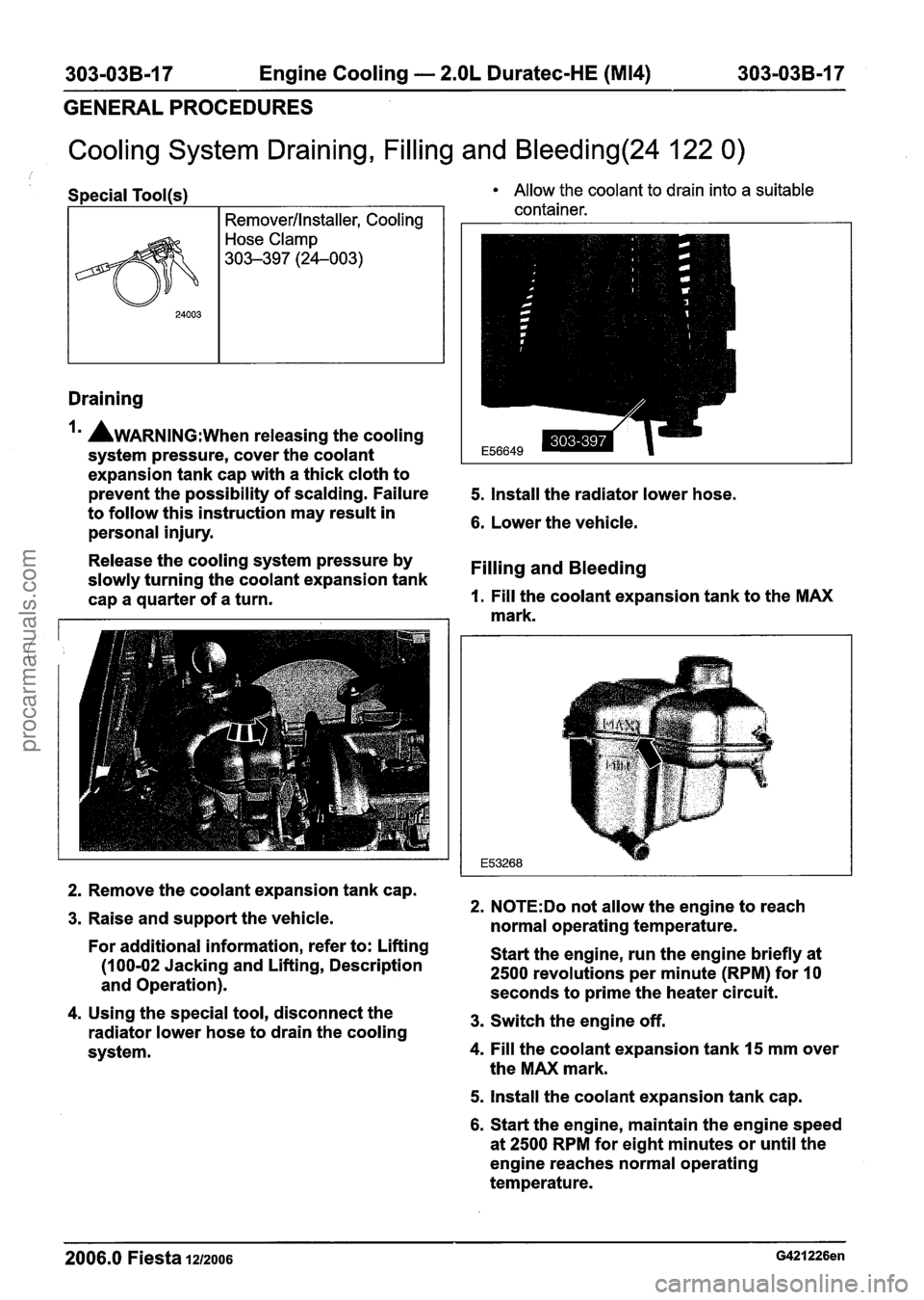
Release the cooling system pressure by
slowly turning the coolant expansion tank
Filling and Bleeding
cap a quarter of a turn. 1. Fill the coolant expansion tank to the MAX
mark.
container.
24003
2. Remove the coolant expansion tank cap.
3. Raise and support the vehicle.
For additional information, refer to: Lifting
(1 00-02 Jacking and Lifting, Description
and Operation).
4. Using the special tool, disconnect the
radiator lower hose to drain the cooling
system.
Removerllnstaller, Cooling
Hose Clamp
303-397 (24-003)
2. N0TE:Do not allow the engine to reach
normal operating temperature.
Start the engine, run the engine briefly at
2500 revolutions per minute (RPM) for 10
seconds to prime the heater circuit.
3. Switch the engine off.
4. Fill the coolant expansion tank 15 mm over
the MAX mark.
5. Install the coolant expansion tank cap.
6. Start the engine, maintain the engine speed
at
2500 RPM for eight minutes or until the
engine reaches normal operating
temperature.
2006.0 Fiesta 1212006
procarmanuals.com
Page 856 of 1226
303-05-1 8 Accessory Drive 303-05-1 8
REMOVAL AND INSTALLATION
Accessory Drive Belt - 1.4L Duratec-1 6V (Sigma)/l .6L
Duratec-1
6V (Sigma), Vehicles With: Air
Conditioning(21 567 0)
General Equipment 2. Using paint or typing correction fluid, mark
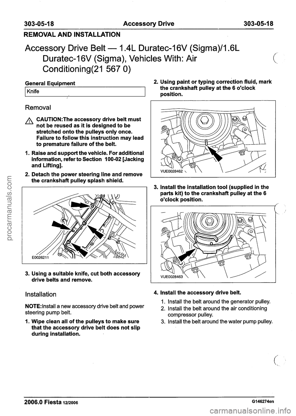
Knife the crankshaft pulley at the 6 o'clock
position.
i
Removal
A CAUTI0N:The accessory drive belt must
not be reused as it is designed to be
stretched onto the pulleys only once.
Failure to follow this instruction may lead
to premature failure of the belt.
I. Raise and support the vehicle. For additional
information, refer to Section
100-02 [Jacking
and Lifting].
2. Detach the power steering line and remove
the crankshaft pulley splash shield.
3. lnstall the installation tool (supplied in the
parts kit) to the crankshaft pulley at the
6
o'clock position. /'
3. Using a suitable knife, cut both accessory
drive belts and remove.
Installation 4. lnstall the accessory drive belt.
1. lnstall the belt around the generator pulley. NOTE: Install a new accessory drive belt and power 2. Install the belt around the air conditioning
steering pump belt. compressor pulley.
I. Wipe clean all of the pulleys to make sure 3. Install the belt around the water pump pulley.
that the accessory drive belt does not slip
during installation.
2006.0 Fiesta 1212006 GI 46274en
procarmanuals.com
Page 859 of 1226
303-05-21 Accessory Drive 303-05-21
REMOVAL AND INSTALLATION
Accessory Drive Belt - 1.4L Duratec-I 6V (Sigma)/l .6L
Duratec-1 6V (Sigma), Vehicles Without: Air
Conditioning(21 567 0)
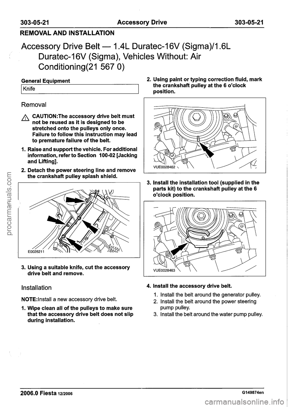
General Equipment 2. Using paint or typing correction fluid, mark
Knife the crankshaft pulley at the 6 o'clock
position.
Removal
A CAUTI0N:The accessory drive belt must
not be reused as it is designed to be
stretched onto the pulleys only once.
Failure to follow this instruction may lead
to premature failure of the belt.
1. Raise and support the vehicle. For additional
information, refer to Section
I 00-02 [Jacking
and Lifting].
2. Detach the power steering line and remove
the crankshaft pulley splash shield.
3. lnstall the installation tool (supplied in the
parts kit) to the crankshaft pulley at the
6
o'clock position.
3. Using a suitable knife, cut the accessory
drive belt and remove.
Installation 4. lnstall the accessory drive belt.
NOTE:
lnstall a new accessory drive belt. 1. lnstall the belt around the generator pulley.
2. lnstall the belt around the power steering
1. Wipe clean all of the pulleys to make sure pump pulley.
that the accessory drive belt does not slip 3. Install the belt around the water pump pulley.
during installation.
2006.0 Fiesta 1212006 Gl49874en
procarmanuals.com
Page 862 of 1226
303-05-24 Accessory Drive 303-05-24
REMOVAL AND INSTALLATION
Power Steering Pump Belt - 1.4L Duratec-1 6V (Sigma)/l .6L
Duratec-1 6V (Sigma), Vehicles With: Air
Conditioning(21 567 0)
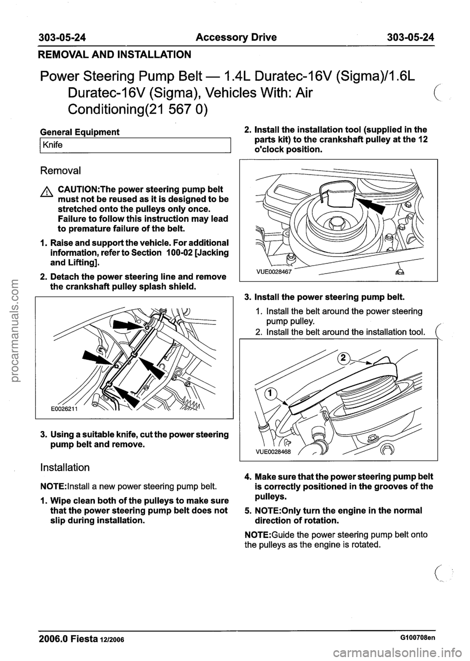
General Equipment 2. Install the installation tool (supplied in the
Knife parts kit) to the crankshaft pulley at the 12
o'clock position.
Removal
A CAUTI0N:The power steering pump belt
must not be reused as it is designed to be
stretched onto the pulleys only once.
Failure to follow this instruction may lead
to premature failure of the belt.
1. Raise and support the vehicle. For additional
information, refer to Section
100-02 [Jacking
and Lifting].
2. Detach the power steering line and remove
the crankshaft pulley splash shield.
3. Install the power steering pump belt.
I. Install the belt around the power steering
pump pulley.
2. Install the belt around the installation tool. (
Installation
4. Make sure that the power steering pump belt
N0TE:lnstall a new power steering pump belt. is correctly positioned in the grooves of the
1. Wipe clean both of the pulleys to make sure pulleys.
that the power steering pump belt does not
5. N0TE:Only turn the engine in the normal
slip during installation.
direction of rotation.
N0TE:Guide the power steering pump belt onto
the pulleys as the engine is rotated.
2006.0 Fiesta 1212006 GI 00708en
procarmanuals.com
Page 864 of 1226
303-05-26 Accessory Drive 303-05-26
REMOVAL AND INSTALLATION
Accessory Drive Belt - 2.OL Duratec-HE (M14)(21 567 0)
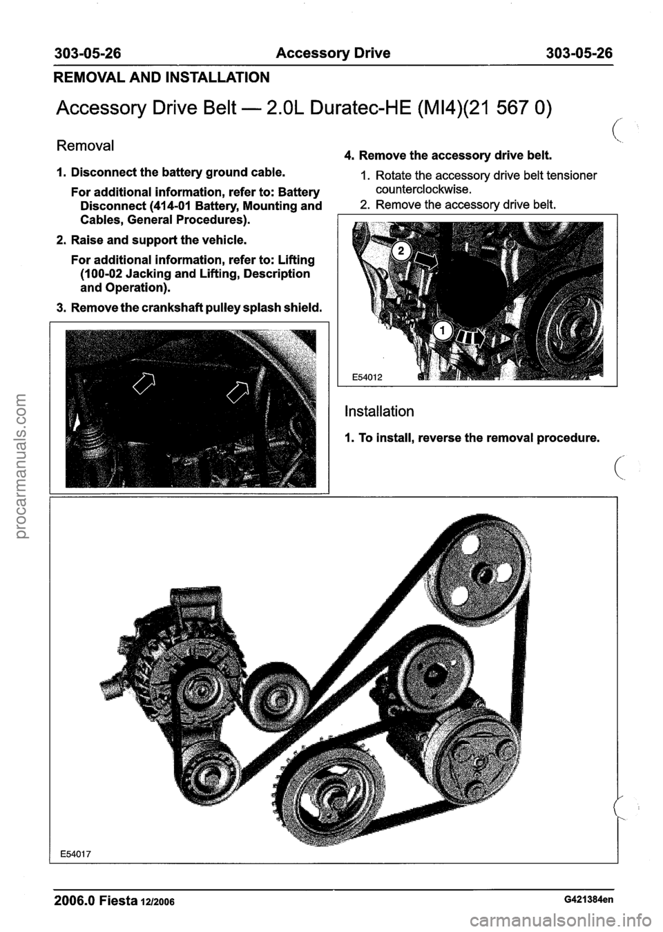
Removal 4. Remove the accessory drive belt.
I. Disconnect the battery ground cable. 1. Rotate the accessory drive belt tensioner
For additional information, refer to: Battery counterclockwise.
Disconnect
(41 4-01 Battery, Mounting and 2. Remove the accessory drive belt.
Cables,
~eneral procedures).
-
2. Raise and support the vehicle.
For additional information, refer to: Lifting
(100-02 Jacking and Lifting, Description
and Operation).
3. Remove the crankshaft pulley splash shield.
2006.0 Fiesta 1212006 G421384en
procarmanuals.com
Page 875 of 1226
303-06-1 I Starting System 303-06-1 1
REMOVAL AND INSTALLATION
Starter Motor - 1.3L Duratec-8V (Rocam)/l.25L Duratec-I 6V
I \, (Sigma)/l.4L Duratec-1 6V (Sigma)/l .6L Duratec-1 6V
(Sigma)(26 204 0)
Removal
I. Disconnect the battery ground cable. For
additional information, refer to
Section
414-01 [Battery, Mounting and
Cables].
2. Raise and support the vehicle. For additional
information, refer to Section
100-02 [Jacking
and Lifting].
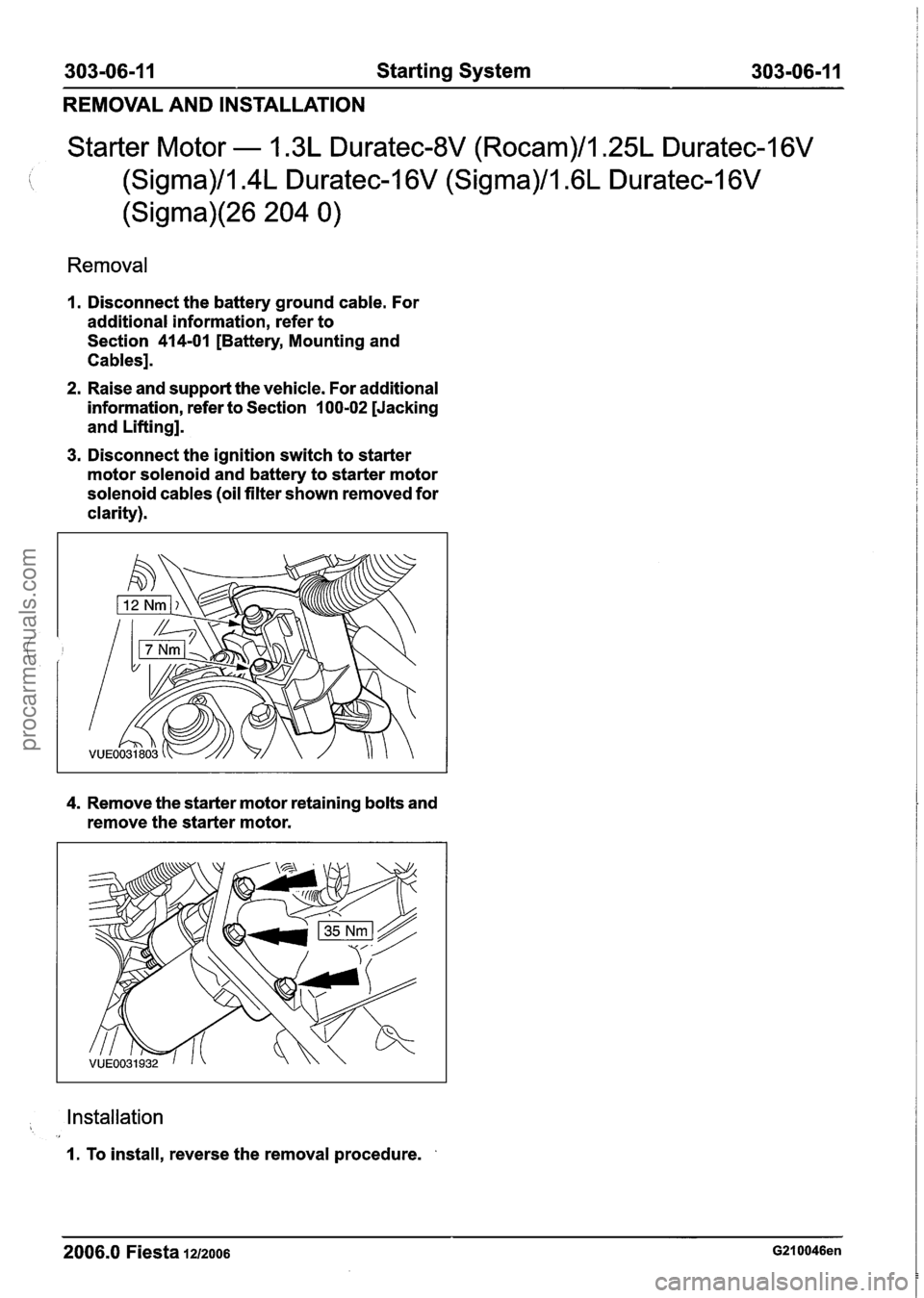
3. Disconnect the ignition switch to starter
motor solenoid and battery to starter motor
solenoid cables (oil filter shown removed for
clarity).
4. Remove the starter motor retaining bolts and
remove the starter motor.
, Installation
I. To install, reverse the removal procedure.
2006.0 Fiesta 1212006 G210046en
procarmanuals.com
Page 876 of 1226
303-06-1 2 Starting System 303-06-1 2
REMOVAL AND INSTALLATION
Starter Motor - 2.OL Duratec-HE (M14)
/'
I. Disconnect the battery ground cable. 2. Raise and support the vehicle. (.. . ,,
For additional information, refer to: Battery For additional
information, refer to: Lifting
Disconnect
(414-01 Battery, Mounting and (1 00-02 Jacking and Lifting, Description
Cables, General Procedures). and
Operation).
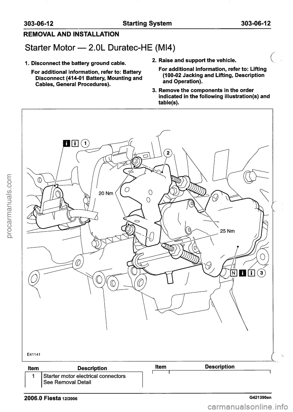
3. Remove the components in the order
indicated in the following
illustration(s) and
table(s).
2006.0 Fiesta 1212006 G421390en
Item Description Item Description I I I 1 Starter motor electrical connectors
See Removal Detail
procarmanuals.com
Page 922 of 1226
303-1 34 Evaporative Emissions 303-1 3-4
REMOVAL AND INSTALLATION
Evaporative Emission Canister - 1.3L Duratec-8V (Rocam)/l.25L
Duratec-1 6V (Sigma)/l.4L Duratec-I 6V (Sigma)/l .6L
Duratec-1
6V (Sigma)(29 250 0)
c
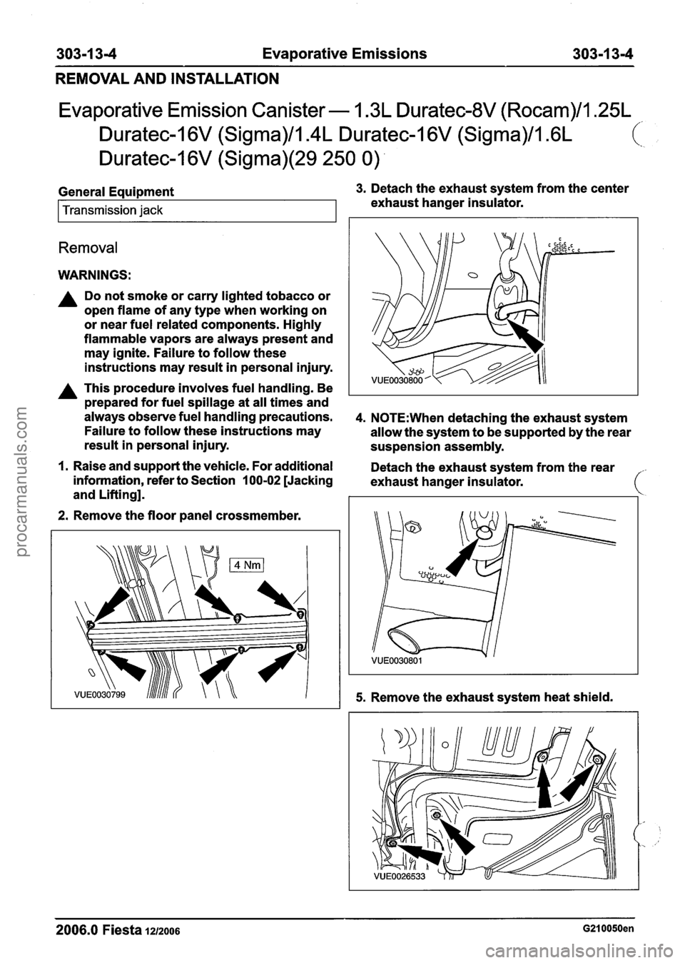
General Equipment 3. Detach the exhaust system from the center
Transmission jack exhaust hanger insulator.
Removal
WARNINGS:
A Do not smoke or carry lighted tobacco or
open flame of any type when working on
or near fuel related components. Highly
flammable vapors are always present and
may ignite. Failure to follow these
instructions may result in personal injury.
A This procedure involves fuel handling. Be
prepared for fuel spillage at all times and
always observe fuel handling precautions.
4. N0TE:When detaching the exhaust system
Failure to follow these instructions may
allow the system to be supported by the rear
result in personal injury.
suspension assembly.
I. Raise and support the vehicle. For additional
Detach the exhaust system from the rear
information, refer to Section
100-02 [Jacking
exhaust hanger insulator.
and Lifting].
2. Remove the floor panel crossmember.
5. Remove the exhaust system heat shield.
-
2006.0 Fiesta 1212006 G210050en
procarmanuals.com
Page 948 of 1226
303-1 4-24 Electronic Engine Controls 303-1 4-24
Powertrain Control Module (PCM) - 2.OL Duratec-HE (M14),
Vehicles With: PCM Security Shield c
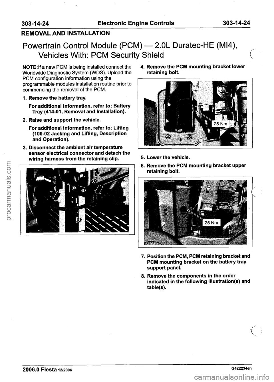
N0TE:lf a new PCM is being installed connect the 4. Remove the PCM mounting bracket lower
Worldwide Diagnostic System (WDS). Upload the retaining bolt.
PCM configuration information using the
programmable modules installation routine prior to
commencing the removal of the PCM.
1. Remove the battery tray.
For additional information, refer to: Battery
Tray
(414-01, Removal and Installation).
2. Raise and support the vehicle.
For additional information, refer to: Lifting
(1 00-02 Jacking and Lifting, Description
and Operation).
3. Disconnect the ambient air temperature
sensor electrical connector and detach the
wiring harness from the retaining clip.
5. Lower the vehicle.
6. Remove the PCM mounting bracket upper
retaining bolt.
7. Position the PCM, PCM retaining bracket and
PCM mounting bracket on the battery tray
support panel.
8. Remove the components in the order
indicated in the following
illustration(s) and
table(s).
2006.0 Fiesta 1212006 G422234en
procarmanuals.com