FORD FIESTA 2007 Workshop Manual
Manufacturer: FORD, Model Year: 2007, Model line: FIESTA, Model: FORD FIESTA 2007Pages: 1226, PDF Size: 61.26 MB
Page 921 of 1226
303-1 3-3 Evaporative Emissions 303-1 3-3
DIAGNOSIS AND TESTING
Evaporative Emissions
i
Inspection and Verification
1. Verify the customer concern.
2. Visually inspect for obvious signs of mechanical
or electrical damage.
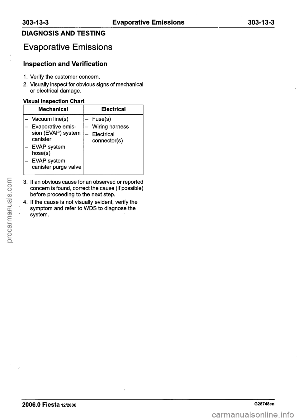
Visual Inspection Chart
I Mechanical I Electrical I
- Vacuum line(s)
- Evaporative emis-
sion (EVAP) system
canister
- EVAP system
hose(s)
- EVAP system
canister purge valve
I - Fuse(s) I I - Wiring harness
- Electrical
connector(s)
3. If an obvious cause for an observed or reported
concern is found, correct the cause (if possible)
before proceeding to the next step.
4. If the cause is not visually evident, verify the
i
' symptom and refer to WDS to diagnose the
' system.
2006.0 Fiesta 12/2006 G28748en
procarmanuals.com
Page 922 of 1226
303-1 34 Evaporative Emissions 303-1 3-4
REMOVAL AND INSTALLATION
Evaporative Emission Canister - 1.3L Duratec-8V (Rocam)/l.25L
Duratec-1 6V (Sigma)/l.4L Duratec-I 6V (Sigma)/l .6L
Duratec-1
6V (Sigma)(29 250 0)
c
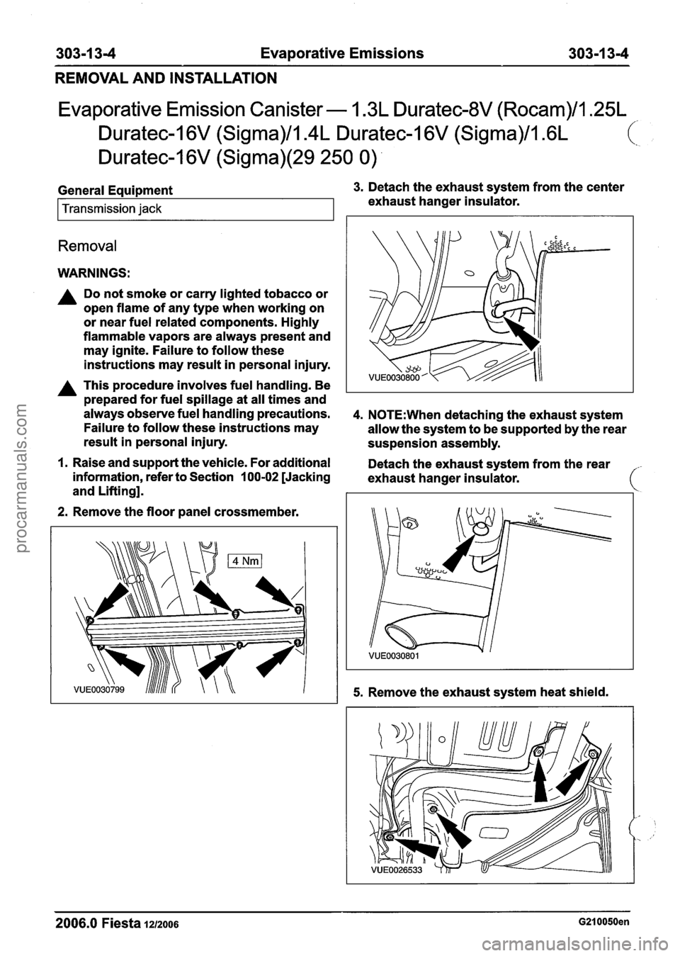
General Equipment 3. Detach the exhaust system from the center
Transmission jack exhaust hanger insulator.
Removal
WARNINGS:
A Do not smoke or carry lighted tobacco or
open flame of any type when working on
or near fuel related components. Highly
flammable vapors are always present and
may ignite. Failure to follow these
instructions may result in personal injury.
A This procedure involves fuel handling. Be
prepared for fuel spillage at all times and
always observe fuel handling precautions.
4. N0TE:When detaching the exhaust system
Failure to follow these instructions may
allow the system to be supported by the rear
result in personal injury.
suspension assembly.
I. Raise and support the vehicle. For additional
Detach the exhaust system from the rear
information, refer to Section
100-02 [Jacking
exhaust hanger insulator.
and Lifting].
2. Remove the floor panel crossmember.
5. Remove the exhaust system heat shield.
-
2006.0 Fiesta 1212006 G210050en
procarmanuals.com
Page 923 of 1226
303-1 3-5 Evaporative Emissions 303-1 3-5
REMOVAL
AND INSTALLATION
ACAUTION:U~~ a suitable packing material 9m ACAUTION:W~~~ lowering the fuel tank,
to prevent damage to the underside of the make
sure that excessive strain is not placed
fuel tank. on
the fuel lines and electrical connectors.
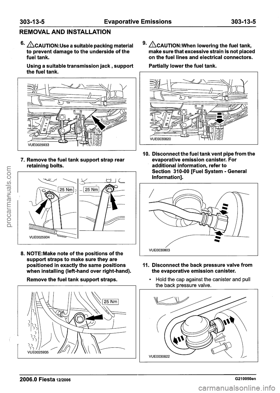
Using a suitable transmission jack, support Partially lower
the fuel tank.
the fuel tank.
10. Disconnect the fuel tank vent pipe from the
7. Remove the fuel tank support strap rear evaporative
emission canister. For
retaining bolts. additional information,
refer to
Section 31 0-00 [Fuel System
- General
Information].
8. N0TE:Make note of the positions of the
support straps to make sure they are
positioned in exactly the same positions
11. Disconnect the back pressure valve from
when installing (left-hand over right-hand). the
evaporative emission canister.
Remove the fuel tank support straps.
Hold the cap against the canister and pull
the back pressure valve.
2006.0 Fiesta 1212006 G210050en
procarmanuals.com
Page 924 of 1226
303-1 3-6 Evaporative Emissions 303-1 3-6
REMOVAL AND INSTALLATION
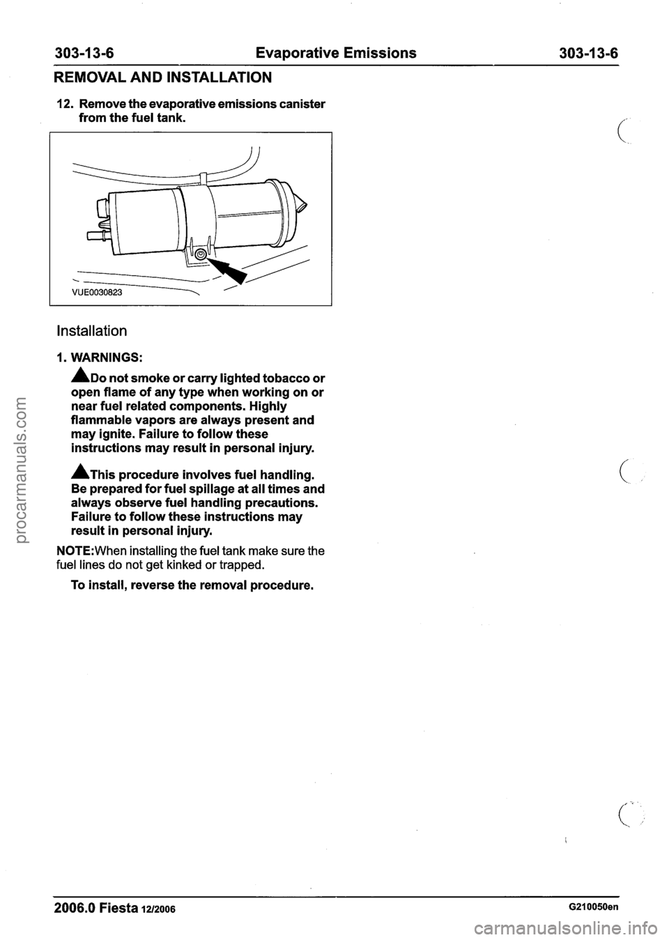
12. Remove the evaporative emissions canister
from the fuel tank.
Installation
1. WARNINGS:
ADO not smoke or carry lighted tobacco or
open flame of any type when working on or
near fuel related components. Highly
flammable vapors are always present and
may ignite. Failure to follow these
instructions may result in personal injury.
A~his procedure involves fuel handling.
Be prepared for fuel spillage at all times and
always observe fuel handling precautions.
Failure to follow these instructions may
result in personal injury.
N0TE:When installing the fuel tank make sure the
fuel lines do not get kinked or trapped.
To install, reverse the removal procedure.
2006.0 Fiesta 1212006 G210050en
procarmanuals.com
Page 925 of 1226
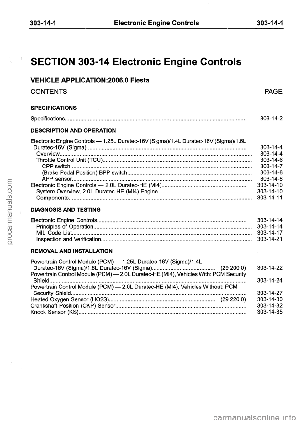
303-1 4-1 Electronic Engine Controls 303-1 4-1
SECTION 303-1 4 Electronic Engine Controls
VEHICLE APPLICATION:2006.0 Fiesta
CONTENTS PAGE
SPECIFICATIONS
Specifications ........................................................................\
.............................................. 303-1 4-2
DESCRIPTION AND OPERATION
Electronic Engine Controls . 1.25L Duratec-16V (Sigma)/l.4L Duratec-I 6V (Sigma)/l . 6L
Duratec-1 6V (Sigma) ........................................................................\
................................
Overview ........................................................................\
.....................................................
Throttle Control Unit (TCU) ........................................................................\
.........................
CPP switch ........................................................................\
..............................................
(Brake Pedal Position) BPP switch ........................................................................\
.........
APP sensor ........................................................................\
.............................................
Electronic Engine Controls - 2.OL Duratec-HE (M14) .......................................................
System Overview, 2.OL Duratec HE (M14) Engine .............................................................
........................................................................\
............................................... Components
DIAGNOSIS AND TESTING
Electronic Engine Controls ........................................................................\
..................... 303-1 4-1 4
Principles of Operation
........................................................................\
............................... 303-1 4-1 4
MIL Code List
........................................................................\
............................................. 303-14-1 7
Inspection and Verification ........................................................................\
.......................... 303-1 4-21
REMOVAL AND INSTALLATION
Powertrain Control Module (PCM) . 1.25L Duratec-1 6V (Sigma)/l.4L
Duratec-16V (Sigma)/l.GL Duratec-1 6V (Sigma) ......................................... (29 200 0) 303-14-22
Powertrain Control Module (PCM)
- 2.OL Duratec-HE (M14), Vehicles With: PCM Security
Shield
........................................................................\
................................................... 303-14-24
Powertrain Control Module (PCM)
- 2.OL Duratec-HE (M14), Vehicles Without: PCM
Security Shield
........................................................................\
.......................................... 303-1 4-27
Heated Oxygen Sensor
(H02S) .................................................................. (29 220 0) 303-14-30
Crankshaft Position (CKP) Sensor
........................................................................\
........... 303-1 4-32
Knock Sensor (KS)
........................................................................\
................................ 303-1 4-35
procarmanuals.com
Page 926 of 1226
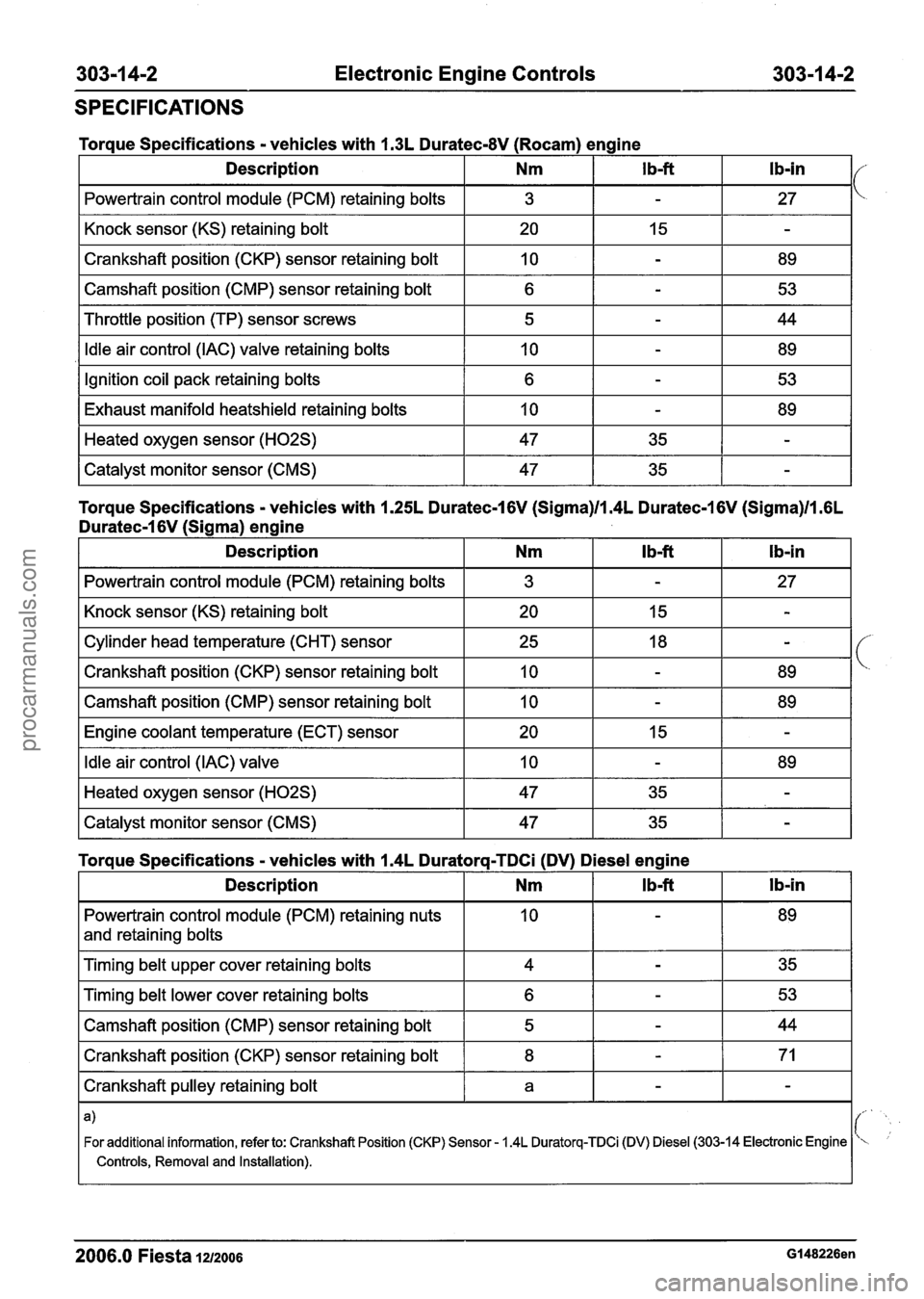
303-1 4-2 Electronic Engine Controls 303-1 4-2
SPECIFICATIONS
I Powertrain control module (PCM) retaining bolts I 3 I - I 27 I
Torque Specifications - vehicles with 1.3L Duratec-8V (Rocam) engine
I Knock sensor (KS) retaining bolt I 20 I 15 I - I
Description
I Crankshaft position (CKP) sensor retaining bolt I 10 I - I 89 I
I Camshaft position (CMP) sensor retaining bolt I
I Throttle position (TP) sensor screws I 5 I - I 44 I
Ib-in I/ Nm
I Idle air control (IAC) valve retaining bolts I 10 I - I 89 I
I b-ft
Ignition coil pack retaining bolts
Exhaust manifold heatshield retaining
bolts
Torque Specifications - vehicles with 1.25L Duratec-1 6V (Sigma)ll.4L Duratec-1 6V (Sigma)ll .6L
Duratec-I 6V (Sigma) engine
Heated oxygen sensor (H02S)
Catalyst monitor sensor (CMS)
I Powertrain control module (PCM) retaining bolts I 3 I - I 27 I
6
10
I Knock sensor (KS) retaining bolt I 20 I 15 I - I
47
47
-
-
I Camshaft position (CMP) sensor retaining bolt I 10 I - I 89 I
53
89
35
35
Cylinder head temperature (CHT) sensor
Crankshaft position (CKP) sensor retaining bolt
I Engine coolant temperature (ECT) sensor I 20 I 15 I - I
-
-
I Idle air control (IAC) valve I 10 I - I 89 I
25
10
I Heated oxygen sensor (H02S) I 47 I 35 I - I -- --
I Catalyst monitor sensor (CMS) 47 I 35 1 - I
18
-
-
89
Powertrain control module (PCM) retaining nuts
and retaining bolts
Torque Specifications - vehicles with 1.4L Duratorq-TDCi (DV) Diesel engine
1 Timing belt upper cover retaining bolts I 4 I - I 35 I
I Timing belt lower cover retaining bolts I 6 I - I 53 I
l b-in
Description
I Camshaft position (CMP) sensor retaining bolt I 5 I - I 44 I
I Crankshaft position (CKP) sensor retaining bolt I 8 I - I 71 I
Nm
I Crankshaft pulley retaining bolt I a I - I - I
I b-ft
I- .
For additional information, refer to: Crankshaft Position (CKP) Sensor - 1.4L Duratorq-Ci D) Diesel (303-14 Electronic Engine ''
I Controls, Removal and Installation).
2006.0 Fiesta 1212006 Gl48226en
procarmanuals.com
Page 927 of 1226
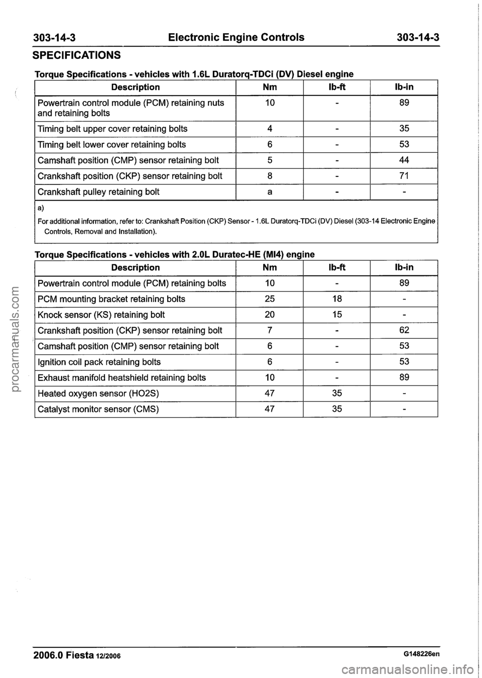
303-1 4-3 Electronic Engine Controls 303-1 4-3
SPECIFICATIONS
control module (PCM) retaining nuts
and retaining bolts
Torque
Specifications
- vehicles with 1.6L Duratorq-TDCi (DV) Diesel engine
I Camshaft position (cMP) sensor retaining bolt I 5 I - I 44 I
lb-in
Timing belt upper cover retaining bolts
Timing belt lower cover retaining bolts
I Crankshaft position (CKP) sensor retaining bolt I 8 I - I 71 I
Ib-ft Description
I Crankshaft pulley retaining bolt I a I - I - I
Nm
4
6
I For additional information, refer to: Crankshaft Position (CKP) Sensor - 1.6L Duratorq-TDCi (DV) Diesel (303-14 Electronic Engine I
I Controls, Removal and Installation). I
-
-
Torque Specifications - vehicles with 2.OL Duratec-HE (M14) eng 35
53
I Description I Nm
ine
I Powertrain control module
(PCM) retaining bolts I 10 I - I 89 I
I PCM mounting bracket retaining bolts I 25 I 18 I - I
I Knock sensor (KS) retaining bolt I 20 I 15 I - I
I Crankshaft position (CKP) sensor retaining bolt I 7
'1 Camshaft position (CMP) sensor retaining bolt I 6
I Ignition coil pack retaining bolts I 6 I - I 53 I
I Exhaust manifold heatshield retaining bolts I 10 I - I 89 I
2006.0 Fiesta 1212006 GI 48226en
-- -
Heated oxygen sensor (H02S)
Catalyst monitor sensor (CMS) 47
47
35
35
-
-
procarmanuals.com
Page 928 of 1226
303-1 4-4 Electronic Engine Controls 303-1 4-4
DESCRIPTION AND OPERATION
Electronic Engine Controls - 1.25L Duratec-1 6V (Sigma)/lAL
Duratec-I 6V (Sigma)/l.GL Duratec-1 6V (Sigma)
Overview
2006.0 Fiesta 1212006 G204204en
procarmanuals.com
Page 929 of 1226

303-1 4-5 Electronic Engine Controls 303-1 4-5
DESCRIPTION AND OPERATION
Item Description Item Description
2006.0 Fiesta 1212006 G204204en
I 1 I Temperature and Manifold Absolute
2 3 1 Knock Sensor (KS)
pressure (T-MAP) sensor
Throttle Position (TP) sensor
4 Sensor - Engine Coolant Temperature
(ECT)
procarmanuals.com
Page 930 of 1226
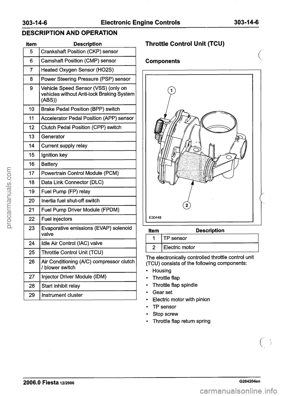
303-1 4-6 Electronic Engine Controls 303-1 4-6
DESCRIPTION
AND OPERATION
Item Descri~tion
1 5 1 Crankshaft Position (CKP) sensor 1
Throttle Control Unit (TCU)
1 6 ( Camshaft Position (CMP) sensor I Components
1 7 1 Heated Oxygen Sensor (H02S) I
1 8 1 Power Steering Pressure (PSP) sensor I
1 10 1 Brake Pedal Position (BPP) switch I
9 Vehicle Speed Sensor (VSS)
(only on
vehicles without Anti-lock Braking System
(ABS))
1 12 1 Clutch Pedal Position (CPP) switch I
11
1 13 1 Generator I
Accelerator Pedal Position (APP) sensor
1 14 1 Current supply relay I
1 15 1 Ignition key I -
16
17
1 20 1 Inertia fuel shut-off switch I
Battery
Powertrain Control Module (PCM)
-
18
19
1 21 1 Fuel Pump Driver Module (FPDM) I
Data Link Connector (DLC)
Fuel Pump (FP) relay
1 22 1 Fuel injectors I
23 Evaporative emissions (EVAP) solenoid
1 lvalve
1 24 1 Idle Air Control (IAC) valve 1
1 25 1 Throttle Control Unit (TCU) I
26 Air Conditioning (AIC) compressor clutch
1 I 1 blower switch
1 27 1 Injector Driver
Module (IDM) I
1 28 1 Start inhibit relay I
1 29 1 Instrument cluster I
Item Descri~tion
I I ITP sensor I
1 2 1 Electric motor I
The electronically controlled throttle control unit
(TCU) consists of the following components:
Housing
Throttle flap
Throttle flap spindle
Gear set
Electric motor with pinion
TP sensor
Stop screw
Throttle flap return spring
2006.0 Fiesta 1212006 G204204en
procarmanuals.com