key FORD FIESTA 2007 Workshop Manual
[x] Cancel search | Manufacturer: FORD, Model Year: 2007, Model line: FIESTA, Model: FORD FIESTA 2007Pages: 1226, PDF Size: 61.26 MB
Page 35 of 1226
100-00-1 9 General Information 100-00-1 9
DESCRIPTION AND OPERATION
Standard Workshop Practices
Vehicle in Workshop
When working on a vehicle in the workshop always
make sure that:
- the parking brake is applied or the wheels are
securely chocked to prevent the vehicle moving
forwards or backwards.
- the key is removed from key operated hood
locks before any work is carried out around the
front of the vehicle.
- if the engine is to be run, there is adequate
ventilation, or an extraction hose to remove
exhaust fumes.
- there is adequate room to raise the vehicle and
remove the wheels, if necessary.
- fender covers are always fitted if any work is to
be carried out in the engine compartment.
- the battery is disconnected if working on the
engine, underneath the vehicle, or if the vehicle
is raised.
Alternative Fuel - Dons
- Do work on the vehicle in a designated area,
that is well ventilated and with access restricted
to qualified personnel only.
- Install new warning labels to their original
locations.
- If possible always isolate the alternative fuel
tank, and run the vehicle on the alternative fuel
until it automatically switches to its normal fuel
prior to taking the vehicle into the workshop
service area.
- Only use tested and approved components and
pipes when repairing or servicing
LPG and CNG
systems.
Alternative Fuel - Do Nots
- Do not vent off LPG fuel.
- Do not use shop air pressure to force LPG fuel
from the fuel tank.
( A CAUTION:When electric arc welding on a - Do not use paint drying ovens above 40°C for vehicle, always disconnect the generator any alternative fuel vehicle. LPG and CNG fuel wiring to prevent the possibility of a surge tanks must be removed from the vehicle prior of current causing damage to the internal to being put into paint drying ovens above 40°C. components of the generator. - Do not modify the system or install new - if using welding equipment on the vehicle, a
components that are not designed for gas
suitable fire extinguisher is readily available.
vehicles.
Alternative Fuel
A WARNING:When servicing the fuel system
always follow the recommended
procedures. Failure to follow these
instructions may result in personal injury.
If the odor of liquefied petroleum gas (LPG) or
compressed natural gas
(CNG) is present in the
air in the workshop, warn all persons in the area
to:
- extinguish all flames and lighted tobacco.
- shut off electrical and air powered equipment.
- evacuate the area.
- ventilate the area.
- contact the fire control authorities.
- remove the vehicle to a dedicated, ventilated
area.
- Do not evacuate fuel tanks unless there is repair
that requires the removal of the fuel tank.
- Do not work on the fuel lines or system
components unless the alternative fuel has been
evacuated and the pressure in the system
reduced to atmospheric or less.
- Do not use anything other than the specified
leak detector fluid to trace fuel leaks.
Be aware of situations that may cause the
LPG or I
CNG fuel system to vent off fuel, such as: I
- extremely hot days.
- parking by a space heater.
- hoisting a vehicle up near a ceiling heater.
Only fully trained personnel, who are conversant
with local standards, are to work on alternative fuel
vehicles.
2006.0 Fiesta 1212006 GI 7373en
procarmanuals.com
Page 107 of 1226
204-01 -9 Front Suspension 204-0 I -9
REMOVAL AND INSTALLATION
Front Stabilizer Bar(l4 752 0)
i , Special Tool(s1
General Equipment
205524
I Transmission jack 1
Alignment Pins, Subframe
205-524 (1 5-1 22)
I Wooden block I
Removal
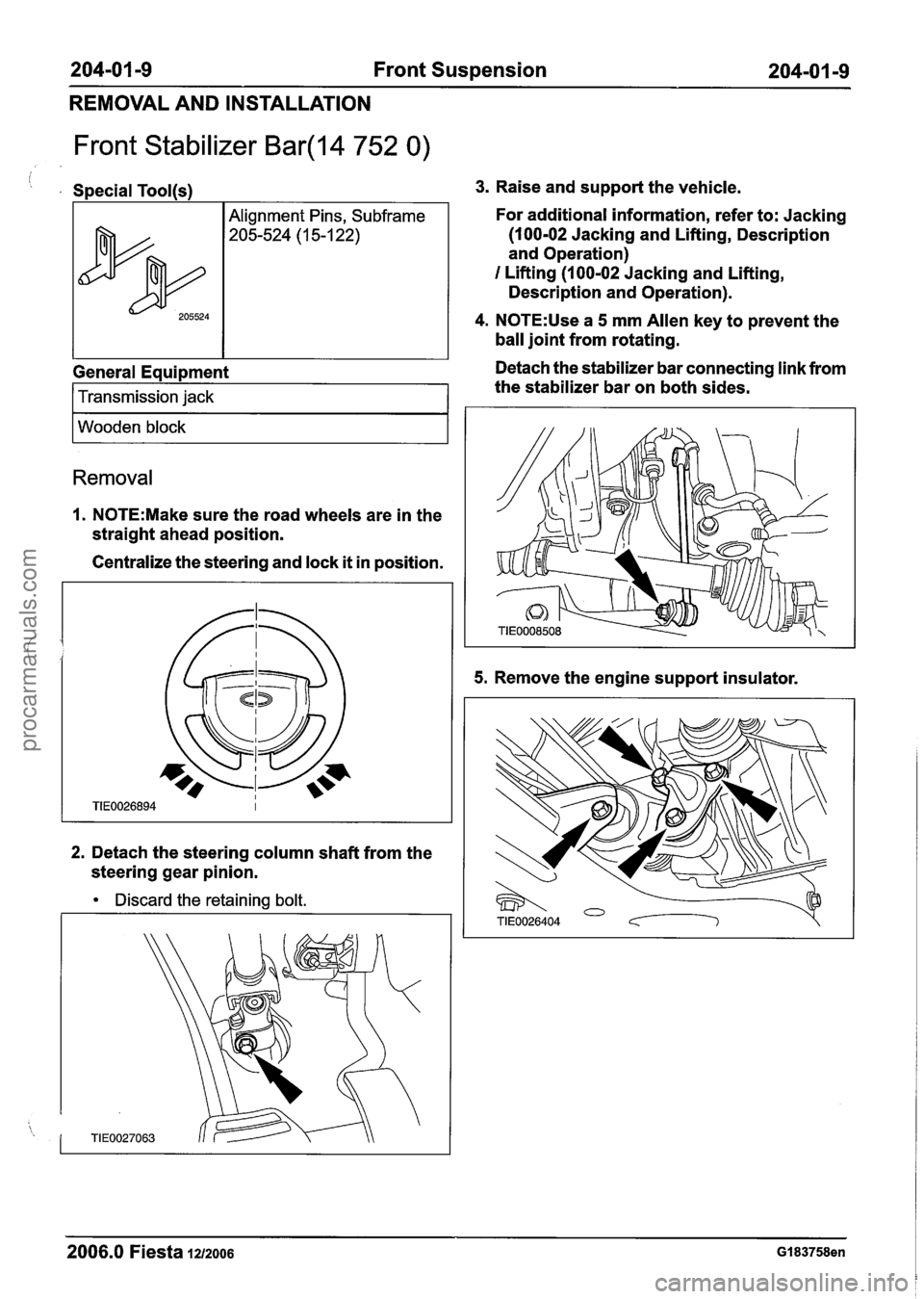
1. N0TE:Make sure the road wheels are in the
straight ahead position.
Centralize the steering and lock
it in position.
2. Detach the steering column shaft from the
steering gear pinion.
Discard the retaining bolt.
3. Raise and support the vehicle.
For additional information, refer to: Jacking
(100-02 Jacking and Lifting, Description
and Operation)
I Lifting (1 00-02 Jacking and Lifting,
Description and Operation).
4. N0TE:Use a 5 mm Allen key to prevent the
ball joint from rotating.
Detach the stabilizer bar connecting link from
the stabilizer bar on both sides.
5. Remove the engine support insulator.
2006.0 Fiesta 1212006 GI 83758en
procarmanuals.com
Page 110 of 1226
204-01 -1 2 Front Suspension 204-01 -1 2 ---- - -
REMOVAL AND INSTALLATION
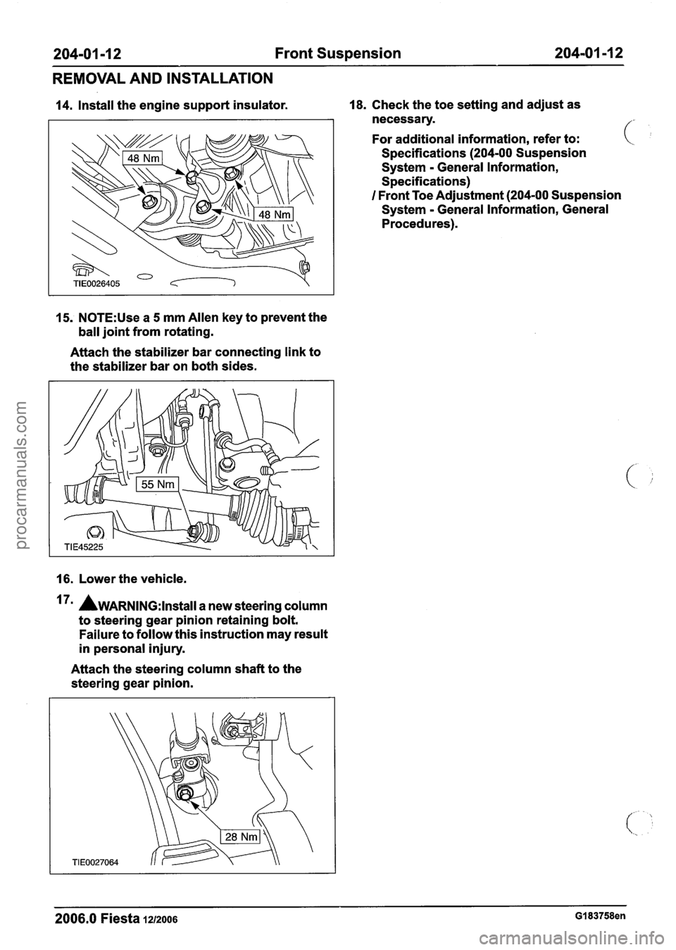
14. Install the engine support insulator. 18. Check the toe setting and adjust as
necessary.
For additional information, refer to:
Specifications
(204-00 Suspension
System
- General Information,
Specifications)
I Front Toe Adjustment (204-00 Suspension
System
- General Information, General
Procedures).
15. N0TE:Use a 5 mm Allen key to prevent the
ball joint from rotating.
Attach the stabilizer bar connecting link to
the stabilizer bar on both sides.
16. Lower the vehicle.
7m AWARNING:I~~~~II a new steering column
to steering gear pinion retaining bolt.
Failure to follow this instruction may result
in personal injury.
Attach the steering column shaft to the
steering gear pinion.
2006.0 Fiesta 1212006 GI 83758en
procarmanuals.com
Page 112 of 1226
204-01 -1 4 Front Suspension 204-01 -1 4
REMOVAL AND INSTALLATION
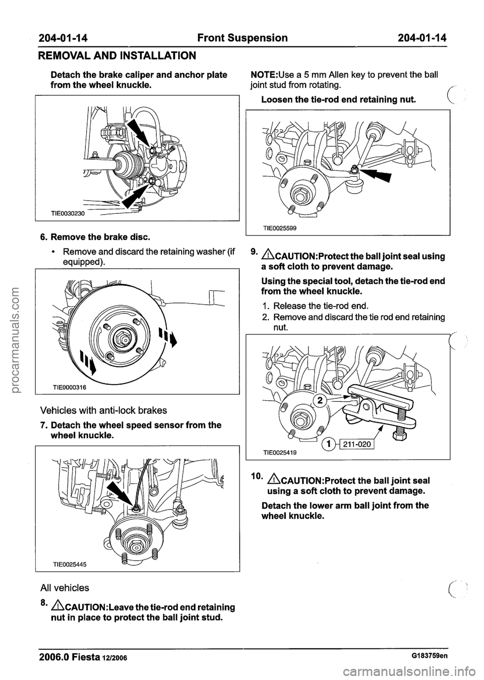
Detach the brake caliper and anchor plate N0TE:Use a 5 mm Allen key to prevent the ball
from the wheel knuckle. joint stud from rotating. f
6. Remove the brake disc.
Remove and discard the retaining washer (if
equipped).
Vehicles with anti-lock brakes
7. Detach the wheel speed sensor from the
wheel knuckle.
All vehicles
*= &AUTION:L~~~~ the tie-rod end retaining
nut in place to protect the ball joint stud. Loosen
the tie-rod end retaining nut.
k
&AuTl~N:~rotect the ball joint seal using
a soft cloth to prevent damage.
Using the special tool, detach the tie-rod end
from the wheel knuckle.
1. Release the tie-rod end.
2. Remove and discard the tie rod end retaining
nut.
/'-
lorn A~AuT10N:~rotect the ball joint seal
using a soft cloth to prevent damage.
Detach the lower arm ball joint from the
wheel knuckle.
2006.0 Fiesta 1212006 GI 83759en
procarmanuals.com
Page 114 of 1226
204-01 -1 6 Front Suspension 204-01 -1 6
REMOVAL AND INSTALLATION
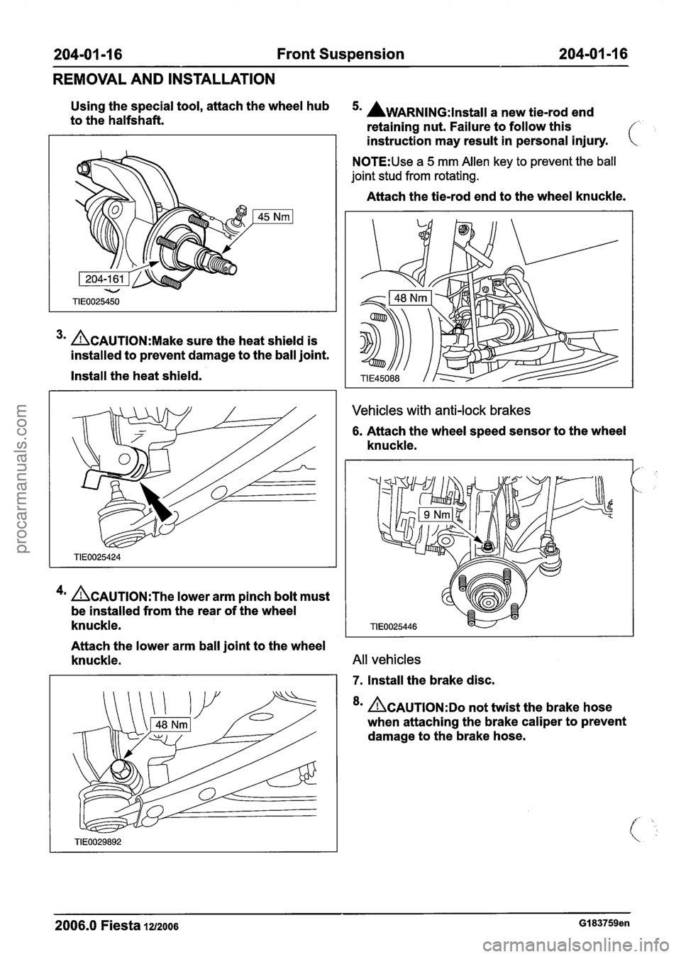
Using the special tool, attach the wheel hub 5. AWARNING:lnstall a new tie-rod end to the halfshaft.
retaining nut. Failure to follow this f
3m ACAUTION:M~~~ sure the heat shield is
installed to prevent damage to the ball joint.
Install the heat shield.
4m &AUTION:T~~ lower arm pinch bolt must
be installed from the rear of the wheel
knuckle. instruction
may result in personal injury.
N0TE:Use a 5 mm Allen key to prevent the ball
joint stud from rotating.
Attach the tie-rod end to the wheel knuckle.
Vehicles with anti-lock brakes
6. Attach the wheel speed sensor to the wheel
knuckle.
Attach the lower arm ball joint to the wheel
knuckle.
All vehicles
7. Install the brake disc.
8m &AUTION:DO not twist the brake hose
when attaching the brake caliper to prevent
damage to the brake hose.
2006.0 Fiesta 1212006 GI 83759en
procarmanuals.com
Page 117 of 1226
204-01 -1 9 Front Suspension 204-01 -1 9
REMOVAL AND INSTALLATION
Front Strut and Spring Assembly(l4 781 0)
, Special Tool(s)
I Lever, Wheel Knuckle
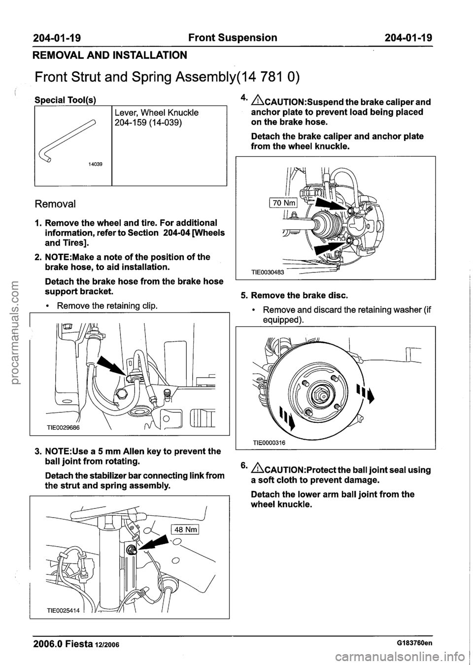
- 4m &AUTION:S~~~~~~ the brake caliper and
anchor plate to prevent load being placed
on the brake hose.
Detach the brake caliper and anchor plate
from the wheel knuckle.
Removal
1. Remove the wheel and tire. For additional
information, refer to Section
204-04 wheels
and Tires].
2. N0TE:Make a note of the position of the
brake hose, to aid installation.
Detach the brake hose from the brake hose
support bracket.
5. Remove the brake disc.
Remove the retaining clip.
Remove and discard the retaining washer (if
equipped).
I
3. N0TE:Use a 5 mm Allen key to prevent the I I
ball joint from rotating.
6m &~u~l~N:~rotect the ball joint seal using
Detach the stabilizer bar connecting link from a cloth to prevent damage. the strut and spring assembly. . - - Detach the lower arm ball joint from the
wheel knuckle.
2006.0 Fiesta 1212006 GI 83760en
procarmanuals.com
Page 121 of 1226
204-01 -23 Front Suspension 204-01 -23
DISASSEMBLY AND ASSEMBLY
Front Strut and Spring Assembly(l4 783 4)
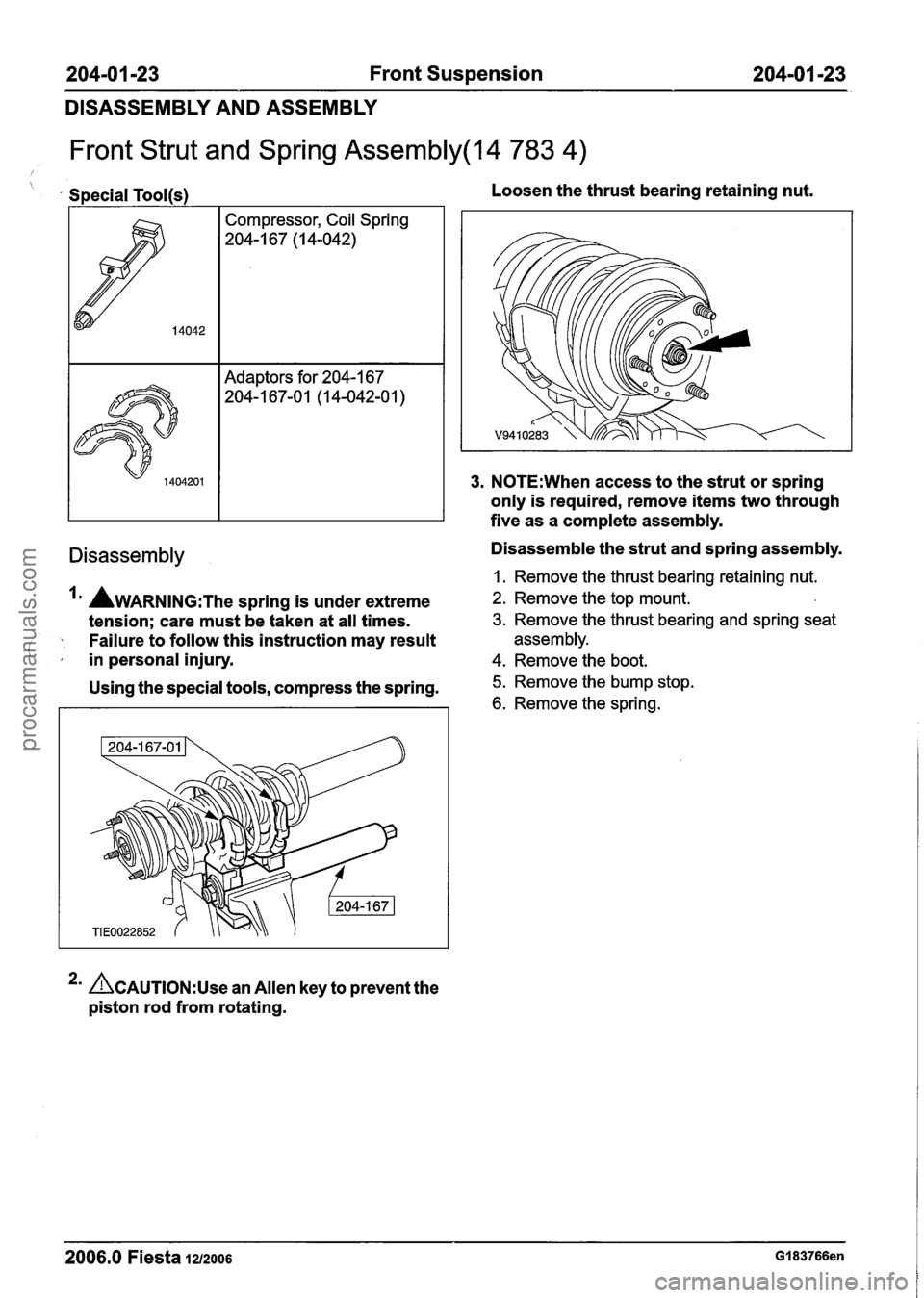
Special Tool(s) I Compressor, Coil Spring
204-1 67 (I 4-042)
Adaptors for 204-1 67
204-1 67-0 1 (1 4-042-0 1
)
Loosen the thrust bearing retaining nut.
3. N0TE:When access to the strut or spring
only is required, remove items two through
five as a complete assembly.
Disassembly Disassemble the strut and spring assembly.
I. Remove the thrust bearing retaining nut.
AWARNING:T~~ spring is under extreme 2. Remove the top mount.
tension; care must be taken at all times. 3. Remove the thrust bearing and spring seat
Failure to follow this instruction may result assembly.
( ,' in personal injury. 4. Remove the boot.
Using the special tools, compress the spring. 5. Remove the bump stop.
6. Remove the spring.
2' &AUTION:U~~ an Allen key to prevent the
piston rod from rotating.
2006.0 Fiesta 1212006 GI 83766en
procarmanuals.com
Page 269 of 1226
206-07-5 Power Brake Actuation 206-07-5
DESCRIPTION AND OPERATION
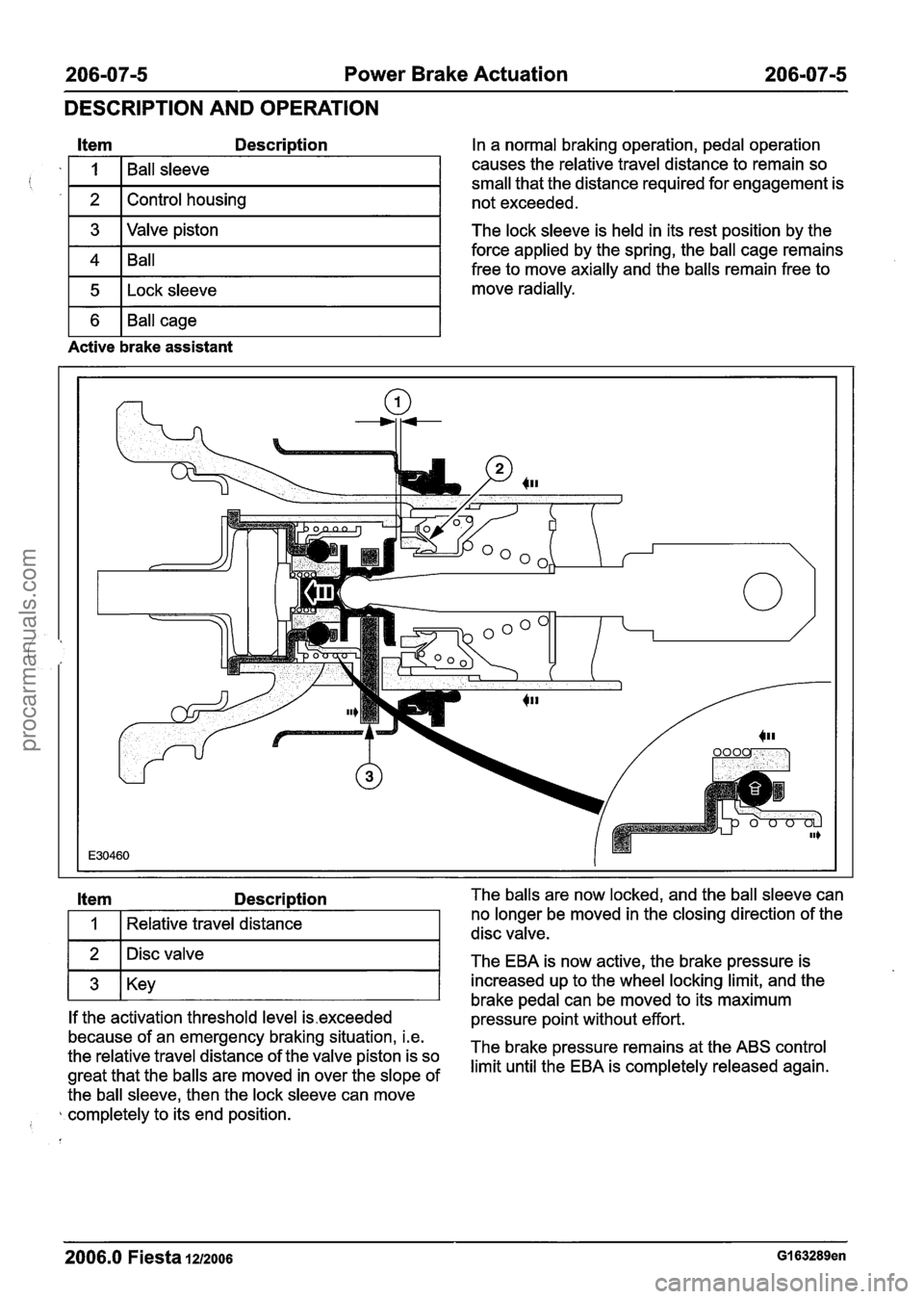
Item Description
1 3 I Valve piston I
i '
1 4 1 Ball I
1 5 1 ~ock sleeve I
I
2
1 6 1 Ball cage I
Ball sleeve
Control housing
Active brake assistant
In a normal braking operation, pedal operation
causes the relative travel distance to remain so
small that the distance required for engagement is
not exceeded.
The lock sleeve is held in its rest position by the
force applied by the spring, the ball cage remains
free to move axially and the balls remain free to
move radially.
Item Description
I 1 I Relative travel distance I
1 2 1 Disc valve I -
1 3 1 Key I
If the activation threshold level is.exceeded
because of an emergency braking situation, i.e.
the relative travel distance of the valve piston is so
great that the balls are moved in over the slope of
the ball sleeve, then the lock sleeve can move
completely to its end position.
I
--
The balls are now locked, and the ball sleeve can
no longer be moved in the closing direction of the
disc valve.
The EBA is now active, the brake pressure is
increased up to the wheel locking limit, and the
brake pedal can be moved to its maximum
pressure point without effort.
The brake pressure remains at the ABS control
limit until the EBA is completely released again.
2006.0 Fiesta 1212006 GI 63289en
procarmanuals.com
Page 270 of 1226
206-0716 Power Brake Actuation 206-0716
DESCRIPTION AND OPERATION
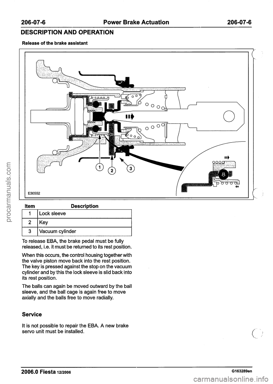
Release of the brake assistant
Item Description
I I I ~ock sleeve I
1 3 IVacuum cylinder I
To release EBA, the brake pedal must be fully
released,
i.e. it must be returned to its rest position.
When this occurs, the control housing together with
the valve piston move back into the rest position.
The key is pressed against the stop on the vacuum
cylinder and by this the lock sleeve is slid back into
its rest position.
The balls can again be moved outward by the ball
sleeve, and the ball cage is again free to move
axially and the balls free to move radially.
Service
It is not possible to repair the EBA. A new brake
servo unit must be installed.
2006.0 Fiesta 12/2006 GI 63289en
procarmanuals.com
Page 373 of 1226
21 1 -02-25 Power Steering 21 1 -02-25
REMOVAL AND INSTALLATION
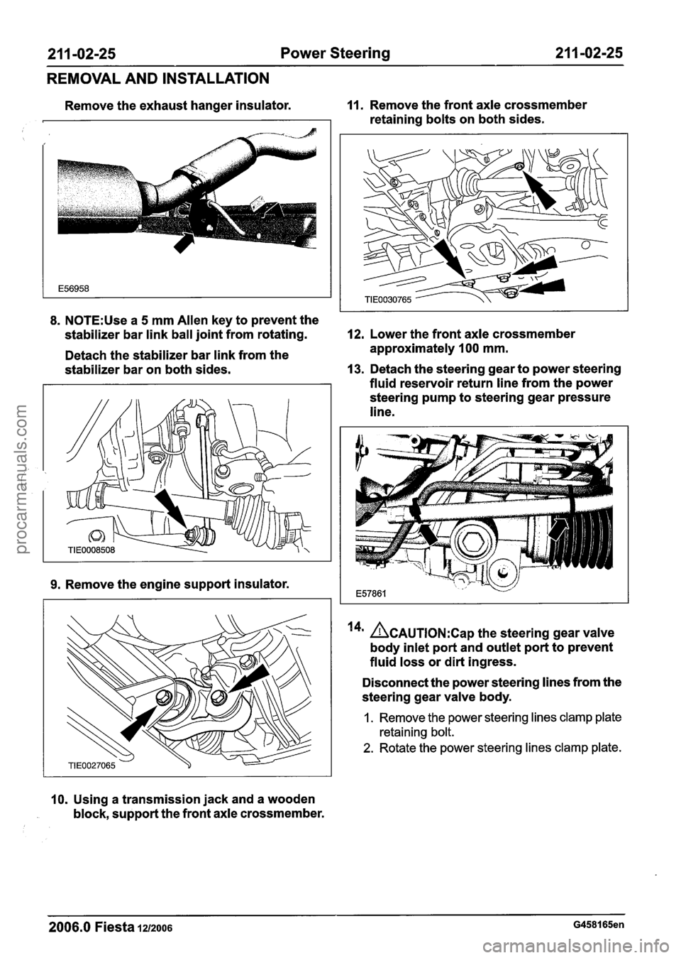
Remove the exhaust hanger insulator. 11. Remove the front axle crossmember
retaining bolts on both sides.
8. N0TE:Use a 5 mm Allen key to prevent the
stabilizer bar link ball joint from rotating.
12. Lower the front axle crossmember
Detach the stabilizer bar link from the approximately
100 mm.
stabilizer bar on both sides.
13. Detach the steering gear to power steering
fluid reservoir return line from the power
steering pump to steering gear pressure
line.
9. Remove the engine support insulator.
10. Using a transmission jack and a wooden
block, support the front axle crossmember.
14' ~CAUTION:C~~ the steering gear valve
body inlet port and outlet port to prevent
fluid loss or dirt ingress.
Disconnect the power steering lines from the
steering gear valve body.
1. Remove the power steering lines clamp plate
retaining bolt.
2. Rotate the power steering lines clamp plate.
2006.0 Fiesta 1212006 G458165en
procarmanuals.com