FORD MONDEO 1993 Service Manual PDF
Manufacturer: FORD, Model Year: 1993, Model line: MONDEO, Model: FORD MONDEO 1993Pages: 279, PDF Size: 12.71 MB
Page 71 of 279
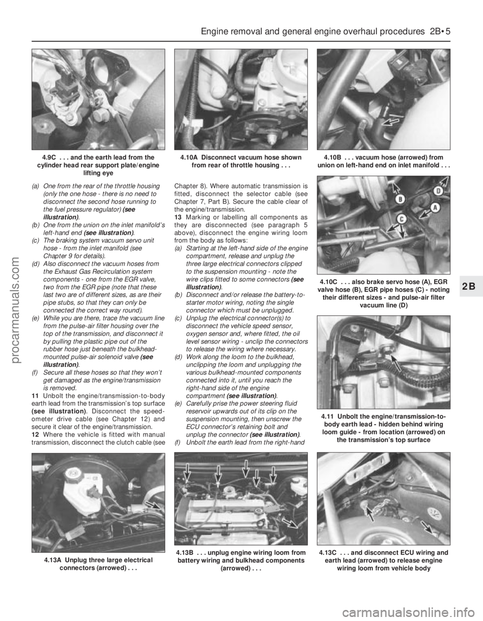
(a) One from the rear of the throttle housing
(only the one hose - there is no need to
disconnect the second hose running to
the fuel pressure regulator) (see
illustration).
(b) One from the union on the inlet manifold’s
left-hand end (see illustration).
(c) The braking system vacuum servo unit
hose - from the inlet manifold (see
Chapter 9 for details).
(d) Also disconnect the vacuum hoses from
the Exhaust Gas Recirculation system
components - one from the EGR valve,
two from the EGR pipe (note that these
last two are of different sizes, as are their
pipe stubs, so that they can only be
connected the correct way round).
(e) While you are there, trace the vacuum line
from the pulse-air filter housing over the
top of the transmission, and disconnect it
by pulling the plastic pipe out of the
rubber hose just beneath the bulkhead-
mounted pulse-air solenoid valve (see
illustration).
(f) Secure all these hoses so that they won’t
get damaged as the engine/transmission
is removed.
11Unbolt the engine/transmission-to-body
earth lead from the transmission’s top surface
(see illustration). Disconnect the speed-
ometer drive cable (see Chapter 12) and
secure it clear of the engine/transmission.
12Where the vehicle is fitted with manual
transmission, disconnect the clutch cable (seeChapter 8). Where automatic transmission is
fitted, disconnect the selector cable (see
Chapter 7, Part B). Secure the cable clear of
the engine/transmission.
13Marking or labelling all components as
they are disconnected (see paragraph 5
above), disconnect the engine wiring loom
from the body as follows:
(a) Starting at the left-hand side of the engine
compartment, release and unplug the
three large electrical connectors clipped
to the suspension mounting - note the
wire clips fitted to some connectors (see
illustration).
(b) Disconnect and/or release the battery-to-
starter motor wiring, noting the single
connector which must be unplugged.
(c) Unplug the electrical connector(s) to
disconnect the vehicle speed sensor,
oxygen sensor and, where fitted, the oil
level sensor wiring - unclip the connectors
to release the wiring where necessary.
(d) Work along the loom to the bulkhead,
unclipping the loom and unplugging the
various bulkhead-mounted components
connected into it, until you reach the
right-hand side of the engine
compartment (see illustration).
(e) Carefully prise the power steering fluid
reservoir upwards out of its clip on the
suspension mounting, then unscrew the
ECU connector’s retaining bolt and
unplug the connector (see illustration).
(f) Unbolt the earth lead from the right-hand
Engine removal and general engine overhaul procedures 2B•5
2B
4.13A Unplug three large electrical
connectors (arrowed) . . .4.13B . . . unplug engine wiring loom from
battery wiring and bulkhead components
(arrowed) . . .4.13C . . . and disconnect ECU wiring and
earth lead (arrowed) to release engine
wiring loom from vehicle body
4.9C . . . and the earth lead from the
cylinder head rear support plate/engine
lifting eye4.10A Disconnect vacuum hose shown
from rear of throttle housing . . .4.10B . . . vacuum hose (arrowed) from
union on left-hand end on inlet manifold . . .
4.10C . . . also brake servo hose (A), EGR
valve hose (B), EGR pipe hoses (C) - noting
their different sizes - and pulse-air filter
vacuum line (D)
4.11 Unbolt the engine/transmission-to-
body earth lead - hidden behind wiring
loom guide - from location (arrowed) on
the transmission’s top surface
procarmanuals.com
Page 72 of 279
inner wing panel, release the engine
wiring loom and refit the power steering
fluid reservoir.
(g) Secure the engine wiring loom neatly to
the engine/transmission so that it cannot
be damaged as the unit is removed from
the vehicle.
14Unbolt both parts of the exhaust manifold
heat shield; unclip the coolant hose to allow
the upper part to be withdrawn.
15Remove the auxiliary drivebelt (see
Chapter 1).
16Unbolt the power steering pump (see
Chapter 10); secure it as far as possible
(without disconnecting the system’s hoses)
clear of the engine/transmission.
17Raise the vehicle and support it securely
on axle stands, then remove the front
roadwheels. Drain the cooling system and (if
the engine is to be dismantled) drain the
engine oil and remove the oil filter (see
Chapter 1). Also drain the transmission as
described in the relevant Part of Chapter 7.
18Withdraw the lower part of the exhaust
manifold heat shield.
19Unscrew the nuts to disconnect the
exhaust system front downpipe from the
manifold, then unhook all the system’s rubber
mountings and withdraw the complete
exhaust system from under the vehicle (see
Chapter 4 for details).
20Where the vehicle is fitted with manual
transmission, mark their positions, then
disconnect the gearchange linkage and
transmission support rods from the rear of the
transmission. Unscrew the retaining nuts, and
withdraw the gear linkage heat shield from the
underbody. Unbolt the rear end of the linkage
from the underbody, swivel the linkage around
to the rear, and tie it to the underbody (see
Chapter 7, Part A, for details).
21Disconnect both anti-roll bar links from
their respective suspension strut - note the
flexible brake hose bracket attached to each
link stud - and both track rod ends from their
steering knuckles. Unfasten the clamp bolt
securing each front suspension lower arm
balljoint to its steering knuckle (see Chap-
ter 10 for details). Check that both balljoints
can be released from the knuckle assemblies
when required, but leave them in place for thetime being, secured by the clamp bolts if
necessary.
22Where the vehicle is fitted with air
conditioning, unbolt the accumulator/
dehydrator from the subframe; secure it as far
as possible (without disconnecting the
system’s hoses) clear of the engine/
transmission.
Warning: Do not disconnect the
refrigerant hoses.
23Unbolt the steering gear from the
subframe; if the bolts are not accessible from
above, a Ford service tool will be required to
reach them from underneath the vehicle (see
Chapter 10 for details).
24Unscrew the two bolts securing the power
steering system pipes to the right-hand side
of the subframe.
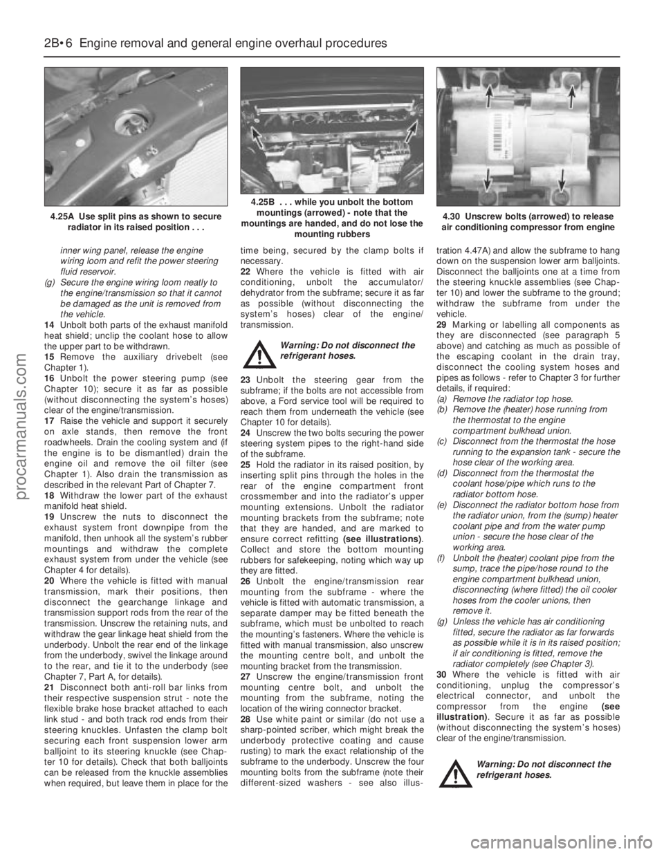
25Hold the radiator in its raised position, by
inserting split pins through the holes in the
rear of the engine compartment front
crossmember and into the radiator’s upper
mounting extensions. Unbolt the radiator
mounting brackets from the subframe; note
that they are handed, and are marked to
ensure correct refitting (see illustrations).
Collect and store the bottom mounting
rubbers for safekeeping, noting which way up
they are fitted.
26Unbolt the engine/transmission rear
mounting from the subframe - where the
vehicle is fitted with automatic transmission, a
separate damper may be fitted beneath the
subframe, which must be unbolted to reach
the mounting’s fasteners. Where the vehicle is
fitted with manual transmission, also unscrew
the mounting centre bolt, and unbolt the
mounting bracket from the transmission.
27Unscrew the engine/transmission front
mounting centre bolt, and unbolt the
mounting from the subframe, noting the
location of the wiring connector bracket.
28Use white paint or similar (do not use a
sharp-pointed scriber, which might break the
underbody protective coating and cause
rusting) to mark the exact relationship of the
subframe to the underbody. Unscrew the four
mounting bolts from the subframe (note their
different-sized washers - see also illus-tration 4.47A) and allow the subframe to hang
down on the suspension lower arm balljoints.
Disconnect the balljoints one at a time from
the steering knuckle assemblies (see Chap-
ter 10) and lower the subframe to the ground;
withdraw the subframe from under the
vehicle.
29Marking or labelling all components as
they are disconnected (see paragraph 5
above) and catching as much as possible of
the escaping coolant in the drain tray,
disconnect the cooling system hoses and
pipes as follows - refer to Chapter 3 for further
details, if required:
(a) Remove the radiator top hose.
(b) Remove the (heater) hose running from
the thermostat to the engine
compartment bulkhead union.
(c) Disconnect from the thermostat the hose
running to the expansion tank - secure the
hose clear of the working area.
(d) Disconnect from the thermostat the
coolant hose/pipe which runs to the
radiator bottom hose.
(e) Disconnect the radiator bottom hose from
the radiator union, from the (sump) heater
coolant pipe and from the water pump
union - secure the hose clear of the
working area.
(f) Unbolt the (heater) coolant pipe from the
sump, trace the pipe/hose round to the
engine compartment bulkhead union,
disconnecting (where fitted) the oil cooler
hoses from the cooler unions, then
remove it.
(g) Unless the vehicle has air conditioning
fitted, secure the radiator as far forwards
as possible while it is in its raised position;
if air conditioning is fitted, remove the
radiator completely (see Chapter 3).
30Where the vehicle is fitted with air
conditioning, unplug the compressor’s
electrical connector, and unbolt the
compressor from the engine (see
illustration). Secure it as far as possible
(without disconnecting the system’s hoses)
clear of the engine/transmission.
Warning: Do not disconnect the
refrigerant hoses.
2B•6 Engine removal and general engine overhaul procedures
4.25A Use split pins as shown to secure
radiator in its raised position . . .
4.25B . . . while you unbolt the bottom
mountings (arrowed) - note that the
mountings are handed, and do not lose the
mounting rubbers
4.30 Unscrew bolts (arrowed) to release
air conditioning compressor from engine
procarmanuals.com
Page 73 of 279
31Where the vehicle is fitted with manual
transmission, disconnect the driveshafts from
the transmission as follows, referring to
Chapter 8 for further details when required:
(a) Unscrew the nuts securing the right-hand
driveshaft support bearing, and withdraw
the heat shield.
(b) Pull the right-hand driveshaft out of the
transmission; be prepared to catch any
spilt oil.
(c) Secure the driveshaft clear of the
engine/transmission - remember that the
unit is to be lowered out of the vehicle -
and ensure that the inner joint is not
turned through more than 18°.
(d) Prise the left-hand driveshaft out of the
transmission - again, be prepared for oil
spillage. Secure the driveshaft clear of the
engine/transmission, and ensure that its
inner joint is not turned through more than
18°.
32Where the vehicle is fitted with automatic
transmission, proceed as follows, referring to
Chapter 7, Part B and to Chapter 8 for further
details when required:
(a) Unscrew its centre bolt, then unbolt the
engine/transmission rear mounting
bracket from the transmission.
(b) Disconnect the fluid cooler pipe from the
rear of the transmission, and secure it
clear of the unit.
(c) Prise the left-hand driveshaft out of the
transmission; be prepared to catch any
spilt oil.
(d) Secure the driveshaft clear of the
engine/transmission - remember that the
unit is to be lowered out of the vehicle -
and ensure that the inner joint is not
turned through more than 18°.
(e) Unscrew the nuts securing the right-hand
driveshaft support bearing, and withdraw
the heat shield.
(f) Pull the right-hand driveshaft out of the
transmission - again, be prepared for oil
spillage. Secure the driveshaft clear of the
engine/transmission, and ensure that its
inner joint is not turned through more than
18°.
(g) Disconnect the fluid cooler pipe from the
front of the transmission, and secure it
clear of the unit.
33The engine/transmission unit should now
be hanging on the right- and left-hand
mountings only, with all components which
connect it to the rest of the vehicle
disconnected or removed and secured well
clear of the unit. Make a final check that this is
the case, then ensure that the body is
securely supported, high enough to permit the
withdrawal of the engine/transmission unit
from underneath; allow for the height of the
engine dolly, if used.
34Take the weight of the engine/
transmission unit, using the lifting eyes
provided on the cylinder head. Unscrew the
six nuts securing the right-hand mounting
bracket, then the three nuts securing the left-
hand bracket. Warning: Do not put any part of
your body under the vehicle, or
under the engine/transmission
unit, when they are supported only by a
hoist or other lifting equipment.
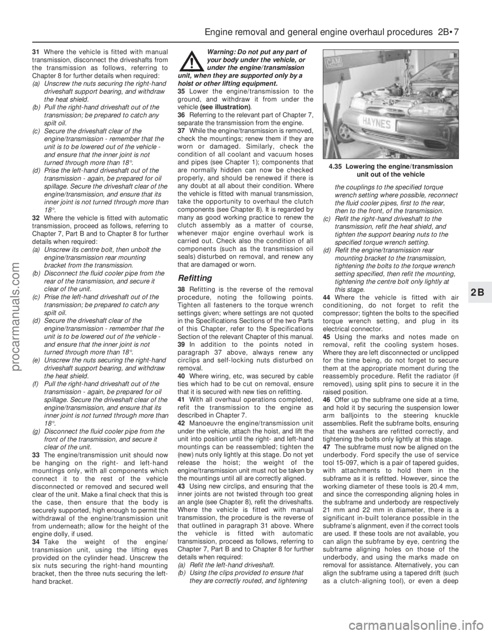
35Lower the engine/transmission to the
ground, and withdraw it from under the
vehicle (see illustration).
36Referring to the relevant part of Chapter 7,
separate the transmission from the engine.
37While the engine/transmission is removed,
check the mountings; renew them if they are
worn or damaged. Similarly, check the
condition of all coolant and vacuum hoses
and pipes (see Chapter 1); components that
are normally hidden can now be checked
properly, and should be renewed if there is
any doubt at all about their condition. Where
the vehicle is fitted with manual transmission,
take the opportunity to overhaul the clutch
components (see Chapter 8). It is regarded by
many as good working practice to renew the
clutch assembly as a matter of course,
whenever major engine overhaul work is
carried out. Check also the condition of all
components (such as the transmission oil
seals) disturbed on removal, and renew any
that are damaged or worn.
Refitting
38Refitting is the reverse of the removal
procedure, noting the following points.
Tighten all fasteners to the torque wrench
settings given; where settings are not quoted
in the Specifications Sections of the two Parts
of this Chapter, refer to the Specifications
Section of the relevant Chapter of this manual.
39In addition to the points noted in
paragraph 37 above, always renew any
circlips and self-locking nuts disturbed on
removal.
40Where wiring, etc, was secured by cable
ties which had to be cut on removal, ensure
that it is secured with new ties on refitting.
41With all overhaul operations completed,
refit the transmission to the engine as
described in Chapter 7.
42Manoeuvre the engine/transmission unit
under the vehicle, attach the hoist, and lift the
unit into position until the right- and left-hand
mountings can be reassembled; tighten the
(new) nuts only lightly at this stage. Do not yet
release the hoist; the weight of the
engine/transmission unit must not be taken by
the mountings until all are correctly aligned.
43Using new circlips, and ensuring that the
inner joints are not twisted through too great
an angle (see Chapter 8), refit the driveshafts.
Where the vehicle is fitted with manual
transmission, the procedure is the reverse of
that outlined in paragraph 31 above. Where
the vehicle is fitted with automatic
transmission, proceed as follows, referring to
Chapter 7, Part B and to Chapter 8 for further
details when required:
(a) Refit the left-hand driveshaft.
(b) Using the clips provided to ensure that
they are correctly routed, and tighteningthe couplings to the specified torque
wrench setting where possible, reconnect
the fluid cooler pipes, first to the rear,
then to the front, of the transmission.
(c) Refit the right-hand driveshaft to the
transmission, refit the heat shield, and
tighten the support bearing nuts to the
specified torque wrench setting.
(d) Refit the engine/transmission rear
mounting bracket to the transmission,
tightening the bolts to the torque wrench
setting specified, then refit the mounting,
tightening the centre bolt only lightly at
this stage.
44Where the vehicle is fitted with air
conditioning, do not forget to refit the
compressor; tighten the bolts to the specified
torque wrench setting, and plug in its
electrical connector.
45Using the marks and notes made on
removal, refit the cooling system hoses.
Where they are left disconnected or unclipped
for the time being, do not forget to secure
them at the appropriate moment during the
reassembly procedure. Refit the radiator (if
removed), using split pins to secure it in the
raised position.
46Offer up the subframe one side at a time,
and hold it by securing the suspension lower
arm balljoints to the steering knuckle
assemblies. Refit the subframe bolts, ensuring
that the washers are refitted correctly, and
tightening the bolts only lightly at this stage.
47The subframe must now be aligned on the
underbody. Ford specify the use of service
tool 15-097, which is a pair of tapered guides,
with attachments to hold them in the
subframe as it is refitted. However, since the
working diameter of these tools is 20.4 mm,
and since the corresponding aligning holes in
the subframe and underbody are respectively
21 mm and 22 mm in diameter, there is a
significant in-built tolerance possible in the
subframe’s alignment, even if the correct tools
are used. If these tools are not available, you
can align the subframe by eye, centring the
subframe aligning holes on those of the
underbody, and using the marks made on
removal for assistance. Alternatively, you can
align the subframe using a tapered drift (such
as a clutch-aligning tool), or even a deep
Engine removal and general engine overhaul procedures 2B•7
2B
4.35 Lowering the engine/transmission
unit out of the vehicle
procarmanuals.com
Page 74 of 279
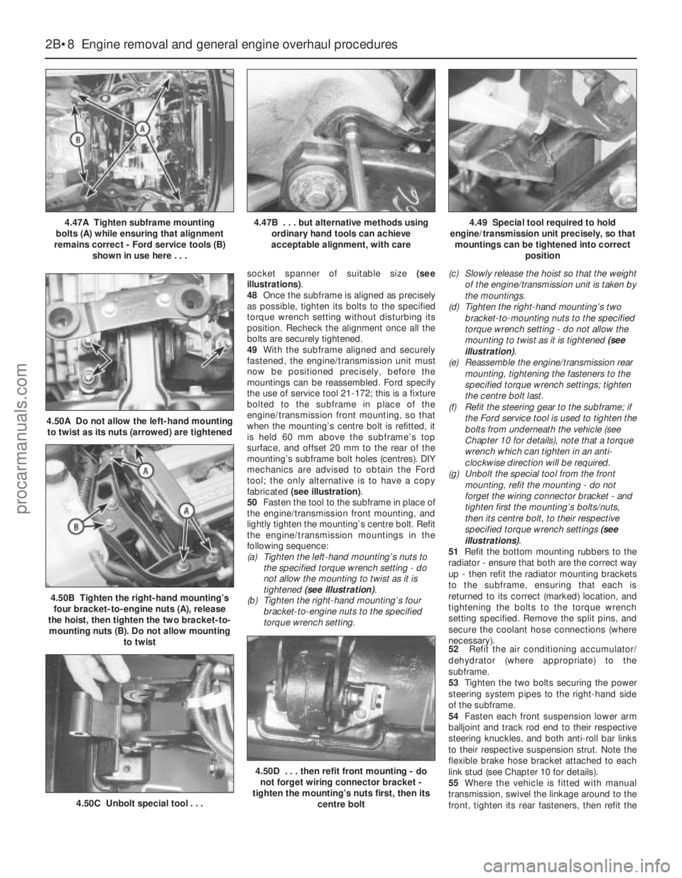
socket spanner of suitable size (see
illustrations).
48Once the subframe is aligned as precisely
as possible, tighten its bolts to the specified
torque wrench setting without disturbing its
position. Recheck the alignment once all the
bolts are securely tightened.
49With the subframe aligned and securely
fastened, the engine/transmission unit must
now be positioned precisely, before the
mountings can be reassembled. Ford specify
the use of service tool 21-172; this is a fixture
bolted to the subframe in place of the
engine/transmission front mounting, so that
when the mounting’s centre bolt is refitted, it
is held 60 mm above the subframe’s top
surface, and offset 20 mm to the rear of the
mounting’s subframe bolt holes (centres). DIY
mechanics are advised to obtain the Ford
tool; the only alternative is to have a copy
fabricated (see illustration).
50Fasten the tool to the subframe in place of
the engine/transmission front mounting, and
lightly tighten the mounting’s centre bolt. Refit
the engine/transmission mountings in the
following sequence:
(a) Tighten the left-hand mounting’s nuts to
the specified torque wrench setting - do
not allow the mounting to twist as it is
tightened (see illustration).
(b) Tighten the right-hand mounting’s four
bracket-to-engine nuts to the specified
torque wrench setting.(c) Slowly release the hoist so that the weight
of the engine/transmission unit is taken by
the mountings.
(d) Tighten the right-hand mounting’s two
bracket-to-mounting nuts to the specified
torque wrench setting - do not allow the
mounting to twist as it is tightened (see
illustration).
(e) Reassemble the engine/transmission rear
mounting, tightening the fasteners to the
specified torque wrench settings; tighten
the centre bolt last.
(f) Refit the steering gear to the subframe; if
the Ford service tool is used to tighten the
bolts from underneath the vehicle (see
Chapter 10 for details), note that a torque
wrench which can tighten in an anti-
clockwise direction will be required.
(g) Unbolt the special tool from the front
mounting, refit the mounting - do not
forget the wiring connector bracket - and
tighten first the mounting’s bolts/nuts,
then its centre bolt, to their respective
specified torque wrench settings (see
illustrations).
51Refit the bottom mounting rubbers to the
radiator - ensure that both are the correct way
up - then refit the radiator mounting brackets
to the subframe, ensuring that each is
returned to its correct (marked) location, and
tightening the bolts to the torque wrench
setting specified. Remove the split pins, and
secure the coolant hose connections (where
necessary).
52Refit the air conditioning accumulator/
dehydrator (where appropriate) to the
subframe.
53Tighten the two bolts securing the power
steering system pipes to the right-hand side
of the subframe.
54Fasten each front suspension lower arm
balljoint and track rod end to their respective
steering knuckles, and both anti-roll bar links
to their respective suspension strut. Note the
flexible brake hose bracket attached to each
link stud (see Chapter 10 for details).
55Where the vehicle is fitted with manual
transmission, swivel the linkage around to the
front, tighten its rear fasteners, then refit the
2B•8 Engine removal and general engine overhaul procedures
4.47A Tighten subframe mounting
bolts (A) while ensuring that alignment
remains correct - Ford service tools (B)
shown in use here . . .4.47B . . . but alternative methods using
ordinary hand tools can achieve
acceptable alignment, with care4.49 Special tool required to hold
engine/transmission unit precisely, so that
mountings can be tightened into correct
position
4.50B Tighten the right-hand mounting’s
four bracket-to-engine nuts (A), release
the hoist, then tighten the two bracket-to-
mounting nuts (B). Do not allow mounting
to twist
4.50A Do not allow the left-hand mounting
to twist as its nuts (arrowed) are tightened
4.50C Unbolt special tool . . .
4.50D . . . then refit front mounting - do
not forget wiring connector bracket -
tighten the mounting’s nuts first, then its
centre bolt
procarmanuals.com
Page 75 of 279
gear linkage heat shield. Reconnect the
gearchange linkage and transmission support
rods to the transmission, adjusting the linkage
using the marks made on removal (see
Chapter 7, Part A, for details).
56Re-install the remaining components and
fasteners in the reverse order of removal.
57Add coolant, engine oil and transmission
fluids as needed (see Chapter 1).
58Run the engine, and check for proper
operation and the absence of leaks. Shut off
the engine, and recheck the fluid levels.
59Remember that, since the front suspension
subframe and steering gear have been
disturbed, the wheel alignment and steering
angles must be checked fully and carefully as
soon as possible, with any necessary
adjustments being made. This operation is best
carried out by an experienced mechanic, using
proper checking equipment; the vehicle should
therefore be taken to a Ford dealer or similarly-
qualified person for attention.
1It is much easier to dismantle and work on
the engine if it is mounted on a portable engine
stand. These stands can often be hired from a
tool hire shop. Before the engine is mounted
on a stand, the flywheel/driveplate should be
removed (Part A of this Chapter, Section 21)
so that the stand bolts can be tightened into
the end of the cylinder block/crankcase.
2If a stand is not available, it is possible to
dismantle the engine with it mounted on
blocks, on a sturdy workbench or on the floor.
Be extra-careful not to tip or drop the engine
when working without a stand.
3If you are going to obtain a reconditioned
engine, all external components must be
removed first, to be transferred to the
replacement engine (just as they will if you are
doing a complete engine overhaul yourself).
Note:When removing the external
components from the engine, pay close
attention to details that may be helpful or
important during refitting. Note the fitted
position of gaskets, seals, spacers, pins,
washers, bolts and other small items.These
external components include the following:
(a) Alternator and brackets (Chapter 5).
(b) HT leads and spark plugs (Chapter 1).
(c) Thermostat and housing (Chapter 3).
(d) Dipstick tube.
(e) Fuel injection system components
(Chapter 4).
(f) All electrical switches and sensors - refer
to the appropriate Chapter.
(g) Inlet and exhaust manifolds (Part A of this
Chapter).
(h) Oil filter (Chapter 1).
(i) Engine/transmission mounting brackets
(Part A of this Chapter, Section 22).
(j) Flywheel/driveplate (Part A of this
Chapter, Section 21).
4If you are obtaining a “short” engine (whichconsists of the engine cylinder
block/crankcase, crankshaft, pistons and
connecting rods all assembled), then the
cylinder head, sump, oil pump, and timing belt
will have to be removed also.
5If you are planning a complete overhaul, the
engine can be dismantled and the internal
components removed in the following order.
(a) Inlet and exhaust manifolds (Part A of this
Chapter).
(b) Timing belt, toothed pulleys and
tensioner, and timing belt inner cover
(Part A of this Chapter).
(c) Cylinder head (Part A of this Chapter,
Section 14).
(d) Flywheel/driveplate (Part A of this
Chapter, Section 21).
(e) Sump (Part A of this Chapter, Section 15).
(f) Oil pump (Part A of this Chapter, Sec-
tion 16).
(g) Piston/connecting rod assemblies
(Section 9).
(h) Crankshaft (Section 10).
6Before beginning the dismantling andoverhaul procedures, make sure that you have
all of the correct tools necessary. Refer to the
introductory pages at the beginning of this
manual for further information.
Note:New and reconditioned cylinder heads
are available from the manufacturers, and
from engine overhaul specialists. Due to the
fact that some specialist tools are required for
the dismantling and inspection procedures,
and new components may not be readily
available (refer to Section 1 of this Part), it may
be more practical and economical for the
home mechanic to purchase a reconditioned
head, rather than to dismantle, inspect and
recondition the original head.
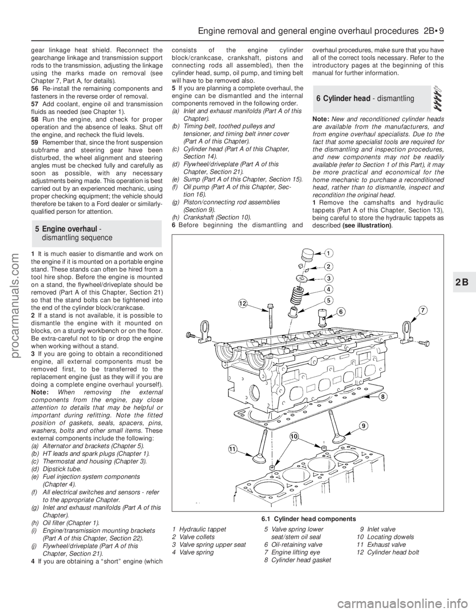
1Remove the camshafts and hydraulic
tappets (Part A of this Chapter, Section 13),
being careful to store the hydraulic tappets as
described (see illustration).
6 Cylinder head - dismantling
5 Engine overhaul-
dismantling sequence
Engine removal and general engine overhaul procedures 2B•9
2B
6.1 Cylinder head components
1 Hydraulic tappet
2 Valve collets
3 Valve spring upper seat
4 Valve spring5 Valve spring lower
seat/stem oil seal
6 Oil-retaining valve
7 Engine lifting eye
8 Cylinder head gasket9 Inlet valve
10 Locating dowels
11 Exhaust valve
12 Cylinder head bolt
procarmanuals.com
Page 76 of 279
2Remove the cylinder head (Part A of this
Chapter, Section 14).
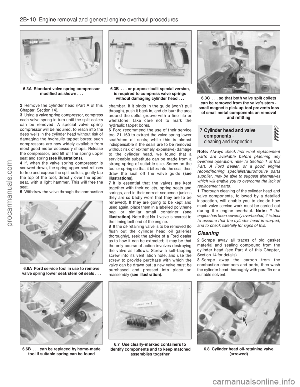
3Using a valve spring compressor, compress
each valve spring in turn until the split collets
can be removed. A special valve spring
compressor will be required, to reach into the
deep wells in the cylinder head without risk of
damaging the hydraulic tappet bores; such
compressors are now widely available from
most good motor accessory shops. Release
the compressor, and lift off the spring upper
seat and spring (see illustrations).
4If, when the valve spring compressor is
screwed down, the spring upper seat refuses
to free and expose the split collets, gently tap
the top of the tool, directly over the upper
seat, with a light hammer. This will free the
seat.
5Withdraw the valve through the combustionchamber. If it binds in the guide (won’t pull
through), push it back in, and de-burr the area
around the collet groove with a fine file or
whetstone; take care not to mark the
hydraulic tappet bores.
6Ford recommend the use of their service
tool 21-160 to extract the valve spring lower
seat/stem oil seals; while this is almost
indispensable if the seals are to be removed
without risk of (extremely expensive) damage
to the cylinder head, we found that a
serviceable substitute can be made from a
strong spring of suitable size. Screw on the
tool or spring so that it bites into the seal, then
draw the seal off the valve guide (see
illustrations).
7It is essential that the valves are kept
together with their collets, spring seats and
springs, and in their correct sequence (unless
they are so badly worn that they are to be
renewed). If they are going to be kept and
used again, place them in a labelled polythene
bag or similar small container (see
illustration). Note that No 1 valve is nearest to
the timing belt end of the engine.
8If the oil-retaining valve is to be removed (to
flush out the cylinder head oil galleries
thoroughly), seek the advice of a Ford dealer
as to how it can be extracted; it may be that
the only course of action involves destroying
the valve as follows. Screw a self-tapping
screw into its ventilation hole, and use the
screw to provide purchase with which the
valve can be drawn out; a new valve must be
purchased and pressed into place on
reassembly (see illustration).Note:Always check first what replacement
parts are available before planning any
overhaul operation; refer to Section 1 of this
Part. A Ford dealer, or a good engine
reconditioning specialist/automotive parts
supplier, may be able to suggest alternatives
which will enable you to overcome the lack of
replacement parts.
1Thorough cleaning of the cylinder head and
valve components, followed by a detailed
inspection, will enable you to decide how
much valve service work must be carried out
during the engine overhaul. Note:If the
engine has been severely overheated, it is best
to assume that the cylinder head is warped,
and to check carefully for signs of this.
Cleaning
2Scrape away all traces of old gasket
material and sealing compound from the
cylinder head (see Part A of this Chapter,
Section 14 for details).
3Scrape away the carbon from the
combustion chambers and ports, then wash
the cylinder head thoroughly with paraffin or a
suitable solvent.
7 Cylinder head and valve
components-
cleaning and inspection
2B•10 Engine removal and general engine overhaul procedures
6.3A Standard valve spring compressor
modified as shown . . .6.3B . . . or purpose-built special version,
is required to compress valve springs
without damaging cylinder head . . .
6.3C . . . so that both valve split collets
can be removed from the valve’s stem -
small magnetic pick-up tool prevents loss
of small metal components on removal
and refitting
6.6B . . . can be replaced by home-made
tool if suitable spring can be found
6.6A Ford service tool in use to remove
valve spring lower seat/stem oil seals . . .
6.7 Use clearly-marked containers to
identify components and to keep matched
assemblies together6.8 Cylinder head oil-retaining valve
(arrowed)
procarmanuals.com
Page 77 of 279
4Scrape off any heavy carbon deposits that
may have formed on the valves, then use a
power-operated wire brush to remove
deposits from the valve heads and stems.
Inspection
Note:Be sure to perform all the following
inspection procedures before concluding that
the services of a machine shop or engine
overhaul specialist are required. Make a list of
all items that require attention.
Cylinder head
5Inspect the head very carefully for cracks,
evidence of coolant leakage, and other
damage. If cracks are found, a new cylinder
head should be obtained.
6Use a straight edge and feeler blade to
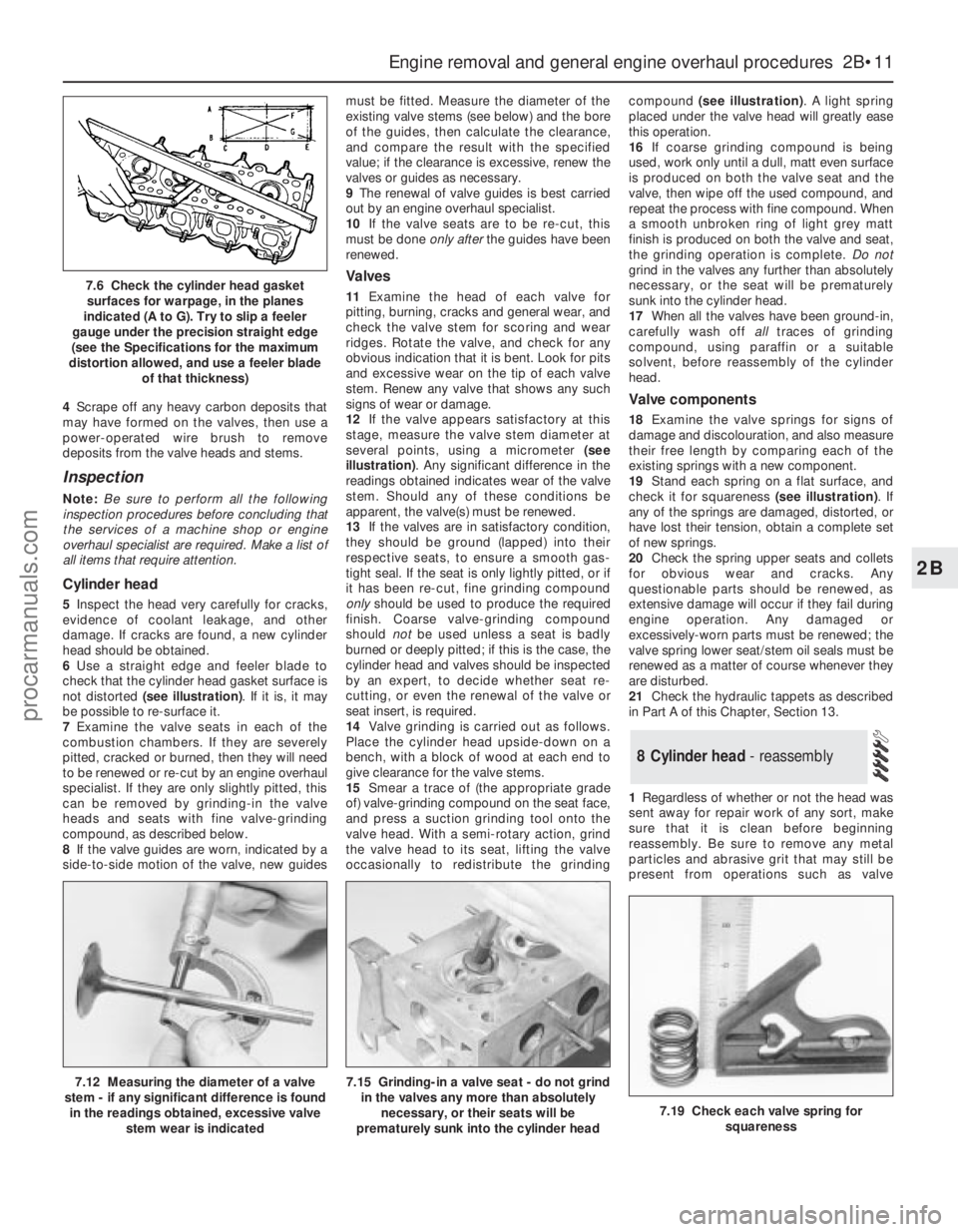
check that the cylinder head gasket surface is
not distorted (see illustration). If it is, it may
be possible to re-surface it.
7Examine the valve seats in each of the
combustion chambers. If they are severely
pitted, cracked or burned, then they will need
to be renewed or re-cut by an engine overhaul
specialist. If they are only slightly pitted, this
can be removed by grinding-in the valve
heads and seats with fine valve-grinding
compound, as described below.
8If the valve guides are worn, indicated by a
side-to-side motion of the valve, new guidesmust be fitted. Measure the diameter of the
existing valve stems (see below) and the bore
of the guides, then calculate the clearance,
and compare the result with the specified
value; if the clearance is excessive, renew the
valves or guides as necessary.
9The renewal of valve guides is best carried
out by an engine overhaul specialist.
10If the valve seats are to be re-cut, this
must be done only afterthe guides have been
renewed.
Valves
11Examine the head of each valve for
pitting, burning, cracks and general wear, and
check the valve stem for scoring and wear
ridges. Rotate the valve, and check for any
obvious indication that it is bent. Look for pits
and excessive wear on the tip of each valve
stem. Renew any valve that shows any such
signs of wear or damage.
12If the valve appears satisfactory at this
stage, measure the valve stem diameter at
several points, using a micrometer (see
illustration). Any significant difference in the
readings obtained indicates wear of the valve
stem. Should any of these conditions be
apparent, the valve(s) must be renewed.
13If the valves are in satisfactory condition,
they should be ground (lapped) into their
respective seats, to ensure a smooth gas-
tight seal. If the seat is only lightly pitted, or if
it has been re-cut, fine grinding compound
onlyshould be used to produce the required
finish. Coarse valve-grinding compound
should notbe used unless a seat is badly
burned or deeply pitted; if this is the case, the
cylinder head and valves should be inspected
by an expert, to decide whether seat re-
cutting, or even the renewal of the valve or
seat insert, is required.
14Valve grinding is carried out as follows.
Place the cylinder head upside-down on a
bench, with a block of wood at each end to
give clearance for the valve stems.
15Smear a trace of (the appropriate grade
of) valve-grinding compound on the seat face,
and press a suction grinding tool onto the
valve head. With a semi-rotary action, grind
the valve head to its seat, lifting the valve
occasionally to redistribute the grindingcompound (see illustration). A light spring
placed under the valve head will greatly ease
this operation.
16If coarse grinding compound is being
used, work only until a dull, matt even surface
is produced on both the valve seat and the
valve, then wipe off the used compound, and
repeat the process with fine compound. When
a smooth unbroken ring of light grey matt
finish is produced on both the valve and seat,
the grinding operation is complete. Do not
grind in the valves any further than absolutely
necessary, or the seat will be prematurely
sunk into the cylinder head.
17When all the valves have been ground-in,
carefully wash off alltraces of grinding
compound, using paraffin or a suitable
solvent, before reassembly of the cylinder
head.
Valve components
18Examine the valve springs for signs of
damage and discolouration, and also measure
their free length by comparing each of the
existing springs with a new component.
19Stand each spring on a flat surface, and
check it for squareness (see illustration). If
any of the springs are damaged, distorted, or
have lost their tension, obtain a complete set
of new springs.
20Check the spring upper seats and collets
for obvious wear and cracks. Any
questionable parts should be renewed, as
extensive damage will occur if they fail during
engine operation. Any damaged or
excessively-worn parts must be renewed; the
valve spring lower seat/stem oil seals must be
renewed as a matter of course whenever they
are disturbed.
21Check the hydraulic tappets as described
in Part A of this Chapter, Section 13.
1Regardless of whether or not the head was
sent away for repair work of any sort, make
sure that it is clean before beginning
reassembly. Be sure to remove any metal
particles and abrasive grit that may still be
present from operations such as valve
8 Cylinder head - reassembly
Engine removal and general engine overhaul procedures 2B•11
2B
7.12 Measuring the diameter of a valve
stem - if any significant difference is found
in the readings obtained, excessive valve
stem wear is indicated7.15 Grinding-in a valve seat - do not grind
in the valves any more than absolutely
necessary, or their seats will be
prematurely sunk into the cylinder head
7.19 Check each valve spring for
squareness
7.6 Check the cylinder head gasket
surfaces for warpage, in the planes
indicated (A to G). Try to slip a feeler
gauge under the precision straight edge
(see the Specifications for the maximum
distortion allowed, and use a feeler blade
of that thickness)
procarmanuals.com
Page 78 of 279
grinding or head resurfacing. Use
compressed air, if available, to blow out all the
oil holes and passages.
2Beginning at one end of the head, lubricate
and install the first valve. Apply molybdenum
disulphide-based grease or clean engine oil to
the valve stem, and refit the valve. Where the
original valves are being re-used, ensure that
each is refitted in its original guide. If new
valves are being fitted, insert them into the
locations to which they have been ground.
3Fit the plastic protector supplied with new
valve spring lower seat/stem oil seals to the
end of the valve stem, then put the new seal
squarely on top of the guide, and leave it
there; the action of refitting the valve spring
presses the lower seat/stem oil seal into place
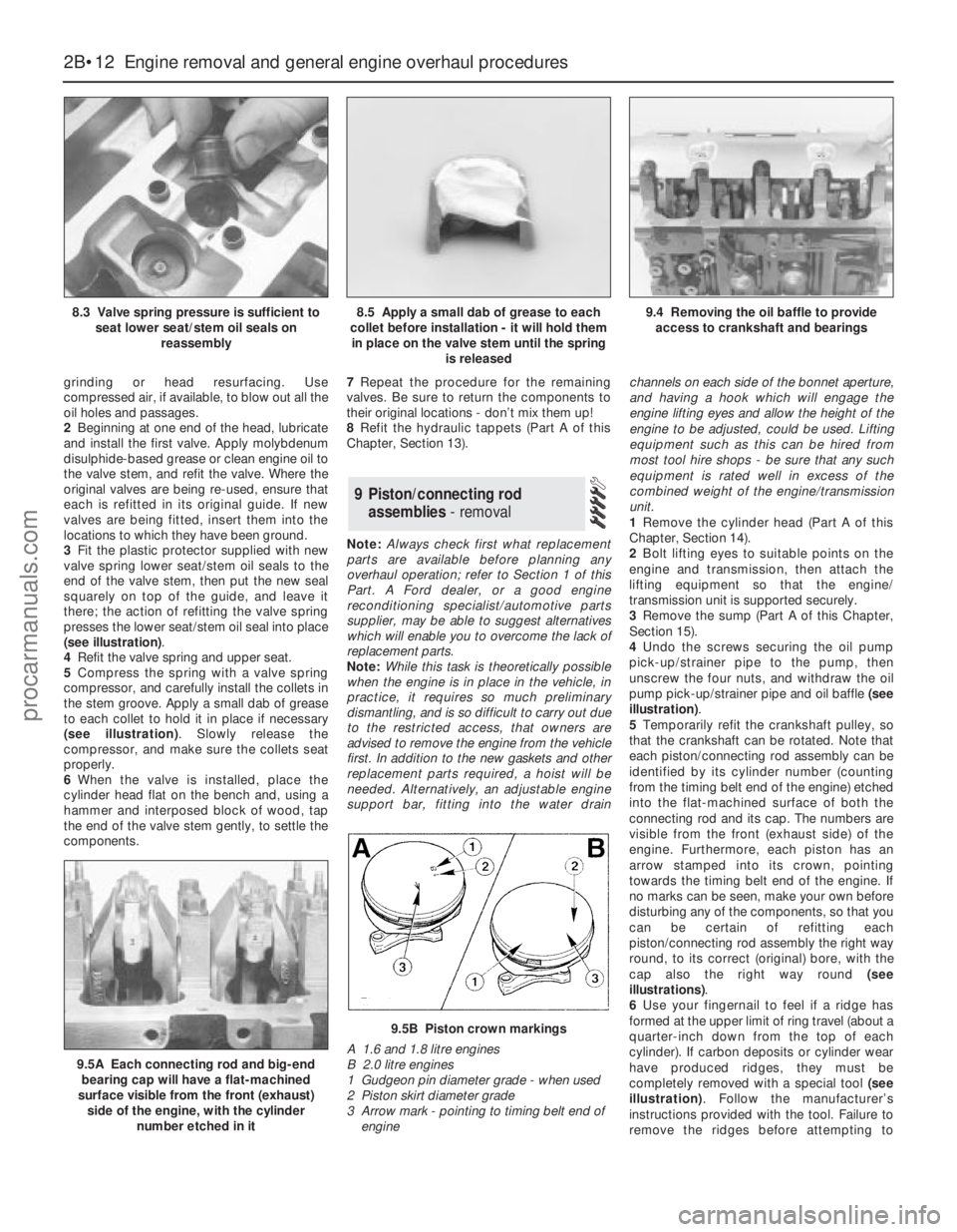
(see illustration).
4Refit the valve spring and upper seat.
5Compress the spring with a valve spring
compressor, and carefully install the collets in
the stem groove. Apply a small dab of grease
to each collet to hold it in place if necessary
(see illustration). Slowly release the
compressor, and make sure the collets seat
properly.
6When the valve is installed, place the
cylinder head flat on the bench and, using a
hammer and interposed block of wood, tap
the end of the valve stem gently, to settle the
components.7Repeat the procedure for the remaining
valves. Be sure to return the components to
their original locations - don’t mix them up!
8Refit the hydraulic tappets (Part A of this
Chapter, Section 13).
Note:Always check first what replacement
parts are available before planning any
overhaul operation; refer to Section 1 of this
Part. A Ford dealer, or a good engine
reconditioning specialist/automotive parts
supplier, may be able to suggest alternatives
which will enable you to overcome the lack of
replacement parts.
Note:While this task is theoretically possible
when the engine is in place in the vehicle, in
practice, it requires so much preliminary
dismantling, and is so difficult to carry out due
to the restricted access, that owners are
advised to remove the engine from the vehicle
first. In addition to the new gaskets and other
replacement parts required, a hoist will be
needed. Alternatively, an adjustable engine
support bar, fitting into the water drainchannels on each side of the bonnet aperture,
and having a hook which will engage the
engine lifting eyes and allow the height of the
engine to be adjusted, could be used. Lifting
equipment such as this can be hired from
most tool hire shops - be sure that any such
equipment is rated well in excess of the
combined weight of the engine/transmission
unit.
1Remove the cylinder head (Part A of this
Chapter, Section 14).
2Bolt lifting eyes to suitable points on the
engine and transmission, then attach the
lifting equipment so that the engine/
transmission unit is supported securely.
3Remove the sump (Part A of this Chapter,
Section 15).
4Undo the screws securing the oil pump
pick-up/strainer pipe to the pump, then
unscrew the four nuts, and withdraw the oil
pump pick-up/strainer pipe and oil baffle (see
illustration).
5Temporarily refit the crankshaft pulley, so
that the crankshaft can be rotated. Note that
each piston/connecting rod assembly can be
identified by its cylinder number (counting
from the timing belt end of the engine) etched
into the flat-machined surface of both the
connecting rod and its cap. The numbers are
visible from the front (exhaust side) of the
engine. Furthermore, each piston has an
arrow stamped into its crown, pointing
towards the timing belt end of the engine. If
no marks can be seen, make your own before
disturbing any of the components, so that you
can be certain of refitting each
piston/connecting rod assembly the right way
round, to its correct (original) bore, with the
cap also the right way round (see
illustrations).
6Use your fingernail to feel if a ridge has
formed at the upper limit of ring travel (about a
quarter-inch down from the top of each
cylinder). If carbon deposits or cylinder wear
have produced ridges, they must be
completely removed with a special tool (see
illustration). Follow the manufacturer’s
instructions provided with the tool. Failure to
remove the ridges before attempting to
9 Piston/connecting rod
assemblies- removal
2B•12 Engine removal and general engine overhaul procedures
8.3 Valve spring pressure is sufficient to
seat lower seat/stem oil seals on
reassembly8.5 Apply a small dab of grease to each
collet before installation - it will hold them
in place on the valve stem until the spring
is released9.4 Removing the oil baffle to provide
access to crankshaft and bearings
9.5A Each connecting rod and big-end
bearing cap will have a flat-machined
surface visible from the front (exhaust)
side of the engine, with the cylinder
number etched in it
9.5B Piston crown markings
A 1.6 and 1.8 litre engines
B 2.0 litre engines
1 Gudgeon pin diameter grade - when used
2 Piston skirt diameter grade
3 Arrow mark - pointing to timing belt end of
engine
procarmanuals.com
Page 79 of 279
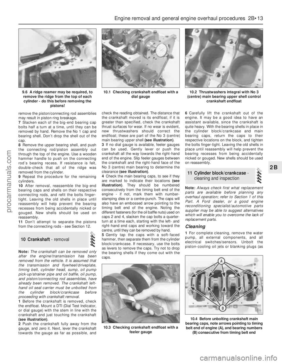
remove the piston/connecting rod assemblies
may result in piston ring breakage.
7Slacken each of the big-end bearing cap
bolts half a turn at a time, until they can be
removed by hand. Remove the No 1 cap and
bearing shell. Don’t drop the shell out of the
cap.
8Remove the upper bearing shell, and push
the connecting rod/piston assembly out
through the top of the engine. Use a wooden
hammer handle to push on the connecting
rod’s bearing recess. If resistance is felt,
double-check that all of the ridge was
removed from the cylinder.
9Repeat the procedure for the remaining
cylinders.
10After removal, reassemble the big-end
bearing caps and shells on their respective
connecting rods, and refit the bolts finger-
tight. Leaving the old shells in place until
reassembly will help prevent the bearing
recesses from being accidentally nicked or
gouged. New shells should be used on
reassembly.
11Don’t attempt to separate the pistons
from the connecting rods - see Section 12.
Note:The crankshaft can be removed only
after the engine/transmission has been
removed from the vehicle. It is assumed that
the transmission and flywheel/driveplate,
timing belt, cylinder head, sump, oil pump
pick-up/strainer pipe and oil baffle, oil pump,
and piston/connecting rod assemblies, have
already been removed. The crankshaft left-
hand oil seal carrier must be unbolted from
the cylinder block/crankcase before
proceeding with crankshaft removal.
1Before the crankshaft is removed, check
the endfloat. Mount a DTI (Dial Test Indicator,
or dial gauge) with the stem in line with the
crankshaft and just touching the crankshaft
(see illustration).
2Push the crankshaft fully away from the
gauge, and zero it. Next, lever the crankshaft
towards the gauge as far as possible, andcheck the reading obtained. The distance that
the crankshaft moved is its endfloat; if it is
greater than specified, check the crankshaft
thrust surfaces for wear. If no wear is evident,
new thrustwashers should correct the
endfloat; these are part of the No 3 (centre)
main bearing upper shell (see illustration).
3If no dial gauge is available, feeler gauges
can be used. Gently lever or push the
crankshaft all the way towards the right-hand
end of the engine. Slip feeler gauges between
the crankshaft and the right-hand face of the
No 3 (centre) main bearing to determine the
clearance (see illustration).
4Check the main bearing caps, to see if they
are marked to indicate their locations (see
illustration). They should be numbered
consecutively from the timing belt end of the
engine - if not, mark them with number-
stamping dies or a centre-punch. The caps will
also have an embossed arrow pointing to the
timing belt end of the engine. Noting the
different fasteners (for the oil baffle nuts) used on
caps 2 and 4, slacken the cap bolts a quarter-
turn at a time each, starting with the left- and
right-hand end caps and working toward the
centre, until they can be removed by hand.
5Gently tap the caps with a soft-faced
hammer, then separate them from the cylinder
block/crankcase. If necessary, use the bolts
as levers to remove the caps. Try not to drop
the bearing shells if they come out with the
caps.6Carefully lift the crankshaft out of the
engine. It may be a good idea to have an
assistant available, since the crankshaft is
quite heavy. With the bearing shells in place in
the cylinder block/crankcase and main
bearing caps, return the caps to their
respective locations on the block, and tighten
the bolts finger-tight. Leaving the old shells in
place until reassembly will help prevent the
bearing recesses from being accidentally
nicked or gouged. New shells should be used
on reassembly.
Note:Always check first what replacement
parts are available before planning any
overhaul operation; refer to Section 1 of this
Part. A Ford dealer, or a good engine
reconditioning specialist/automotive parts
supplier may be able to suggest alternatives
which will enable you to overcome the lack of
replacement parts.
Cleaning
1For complete cleaning, remove the water
pump, all external components, and all
electrical switches/sensors. Unbolt the
piston-cooling oil jets or blanking plugs (as
11 Cylinder block/crankcase -
cleaning and inspection
10 Crankshaft - removal
Engine removal and general engine overhaul procedures 2B•13
2B
10.3 Checking crankshaft endfloat with a
feeler gauge
10.4 Before unbolting crankshaft main
bearing caps, note arrows pointing to timing
belt end of engine (A), and bearing numbers
(B) consecutive from timing belt end
9.6 A ridge reamer may be required, to
remove the ridge from the top of each
cylinder - do this before removing the
pistons!10.1 Checking crankshaft endfloat with a
dial gauge10.2 Thrustwashers integral with No 3
(centre) main bearing upper shell control
crankshaft endfloat
procarmanuals.com
Page 80 of 279
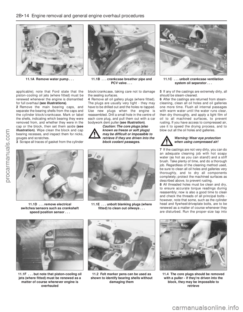
applicable); note that Ford state that the
piston-cooling oil jets (where fitted) must be
renewed whenever the engine is dismantled
for full overhaul (see illustrations).
2Remove the main bearing caps, and
separate the bearing shells from the caps and
the cylinder block/crankcase. Mark or label
the shells, indicating which bearing they were
removed from, and whether they were in the
cap or the block, then set them aside (see
illustration). Wipe clean the block and cap
bearing recesses, and inspect them for nicks,
gouges and scratches.
3Scrape all traces of gasket from the cylinderblock/crankcase, taking care not to damage
the sealing surfaces.
4Remove all oil gallery plugs (where fitted).
The plugs are usually very tight - they may
have to be drilled out and the holes re-tapped.
Use new plugs when the engine is
reassembled. Drill a small hole in the centre of
each core plug, and pull them out with a car
bodywork dent puller (see illustration).
Caution: The core plugs (also
known as freeze or soft plugs)
may be difficult or impossible to
retrieve if they are driven into the
block coolant passages.5If any of the castings are extremely dirty, all
should be steam-cleaned.
6After the castings are returned from steam-
cleaning, clean all oil holes and oil galleries
one more time. Flush all internal passages
with warm water until the water runs clear,
then dry thoroughly, and apply a light film of
oil to all machined surfaces, to prevent
rusting. If you have access to compressed air,
use it to speed the drying process, and to
blow out all the oil holes and galleries.
Warning: Wear eye protection
when using compressed air!
7If the castings are not very dirty, you can do
an adequate cleaning job with hot soapy
water (as hot as you can stand!) and a stiff
brush. Take plenty of time, and do a thorough
job. Regardless of the cleaning method used,
be sure to clean all oil holes and galleries very
thoroughly, and to dry all components
completely; protect the machined surfaces as
described above, to prevent rusting.
8All threaded holes must be clean and dry,
to ensure accurate torque readings during
reassembly; now is also a good time to clean
and check the threads of all principal bolts -
however, note that some, such as the cylinder
head and flywheel/driveplate bolts, are to be
renewed as a matter of course whenever they
are disturbed. Run the proper-size tap into
2B•14 Engine removal and general engine overhaul procedures
11.1A Remove water pump . . .11.1B . . . crankcase breather pipe and
PCV valve . . .11.1C . . . unbolt crankcase ventilation
system oil separator . . .
11.1F . . . but note that piston-cooling oil
jets (where fitted) must be renewed as a
matter of course whenever engine is
overhauled11.2 Felt marker pens can be used as
shown to identify bearing shells without
damaging them
11.1D . . . remove electrical
switches/sensors such as crankshaft
speed/position sensor . . .11.1E . . . unbolt blanking plugs (where
fitted) to clean out oilways . . .
11.4 The core plugs should be removed
with a puller - if they’re driven into the
block, they may be impossible to
retrieve
procarmanuals.com