suspension FORD MUSTANG 1969 Volume One Chassis
[x] Cancel search | Manufacturer: FORD, Model Year: 1969, Model line: MUSTANG, Model: FORD MUSTANG 1969Pages: 413, PDF Size: 75.81 MB
Page 185 of 413
03-13-06
Specifications
03-13-06
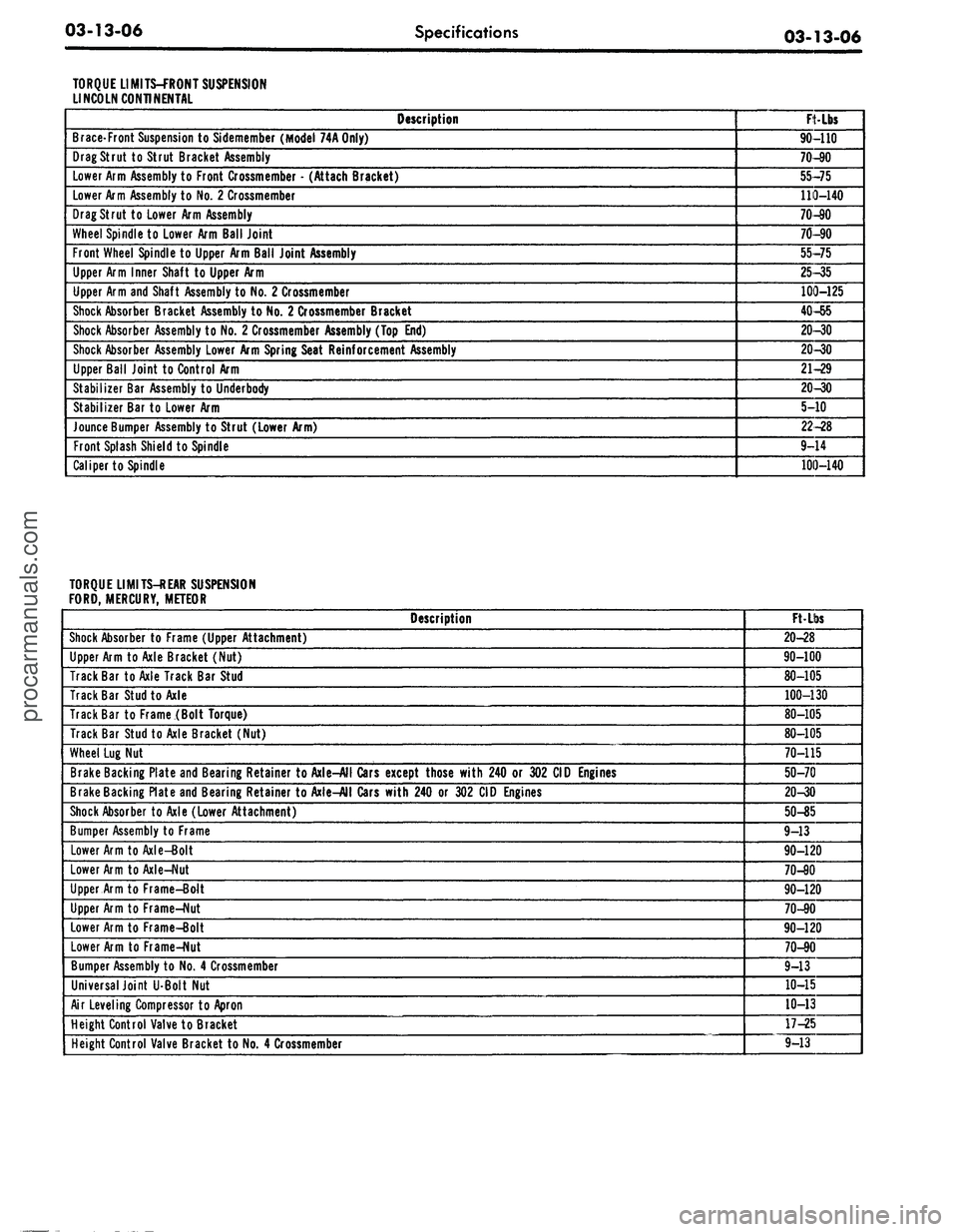
TORQUE LIMITS-FRONT SUSPENSION
LINCOLN CONTINENTAL
Description
Brace-Front Suspension to Sidemember (Model 74A Only)
Drag Strut
to
Strut Bracket Assembly
Lower Arm Assembly to Front Crossmember
-
(Attach Bracket)
Lower Arm Assembly to No. 2 Crossmember
Drag Strut
to
Lower Arm Assembly
Wheel Spindle to Lower Arm Ball Joint
Front Wheel Spindle to Upper Arm Ball Joint Assembly
Upper Arm Inner Shaft
to
Upper Arm
Upper Arm and Shaft Assembly to No. 2 Crossmember
Shock Absorber Bracket Assembly to No. 2 Crossmember Bracket
Shock Absorber Assembly to No. 2 Crossmember Assembly (Top End)
Shock Absorber Assembly Lower Arm Spring Seat Reinforcement Assembly
Upper Ball Joint
to
Control Arm
Stabilizer Bar Assembly
to
Underbody
Stabilizer Bar
to
Lower Arm
Jounce Bumper Assembly
to
Strut (Lower Arm)
Front Splash Shield to Spindle
Caliper to Spindle
FtLbs
90-110
70-90
55-75
110-140
70-90
70-90
55-75
25-35
100-125
40-55
20-30
20-30
21-29
20-30
5-10
22-28
9-14
100-140
TORQUE LIMITS-REAR SUSPENSION
FORD, MERCURY, METEOR
Description
Shock Absorber
to
Frame (Upper Attachment)
Upper Arm to Axle Bracket (Nut)
Track Bar to Axle Track Bar Stud
Track Bar Stud to Axle
Track Bar
to
Frame (Bolt Torque)
Track Bar Stud to Axle Bracket (Nut)
Wheel Lug Nut
Brake Backing Plate and Bearing Retainer to Axle-All Cars except those with 240
or
302 CID Engines
Brake Backing Plate and Bearing Retainer to Axle-All Cars with 240
or
302 CID Engines
Shock Absorber to Axle (Lower Attachment)
Bumper Assembly
to
Frame
Lower Arm to Axle-Bolt
Lower Arm to Axle-Nut
Upper Arm
to
Frame-BoU
Upper Arm
to
Frame-Nut
Lower Arm
to
Frame-Bolt
Lower Arm
to
Frame-Nut
Bumper Assembly to No. 4 Crossmember
Universal Joint
U-Bolt
Nut
Air Leveling Compressor
to
Apron
Height Control Valve to Bracket
Height Control Valve Bracket to No. 4 Crossmember
FtLbs
20-28
90-100
80-105
100-130
80-105
80-105
70-115
50-70
20-30
50-35
9-13
90-120
70-90
90-120
70-90
90-120
70-90
9-13
10-15
10-13
17-25
9-13procarmanuals.com
Page 186 of 413
03-13-07
Specifications
03-13-07
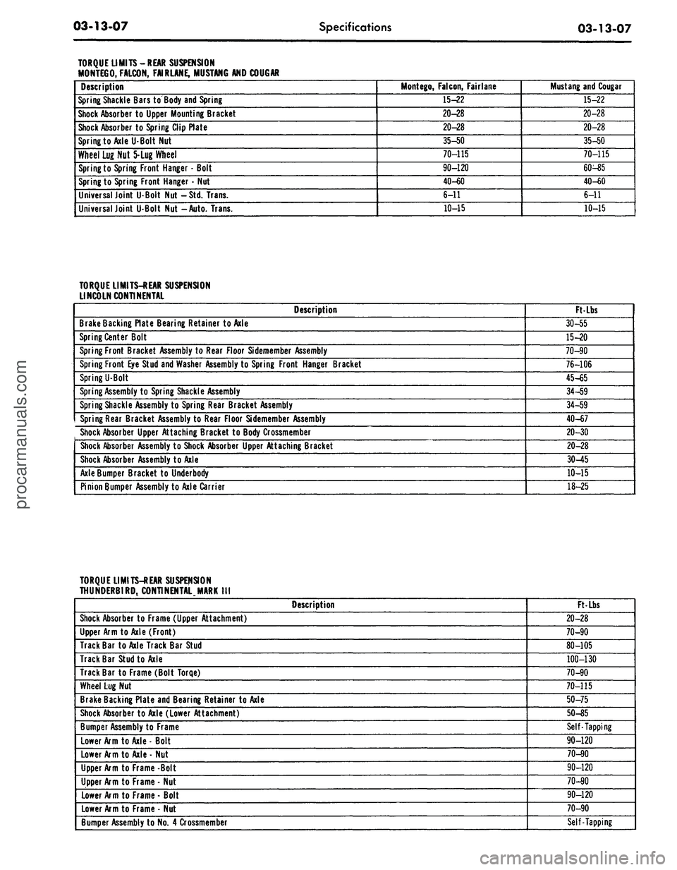
TORQUE LIMITS-REAR SUSPENSION
MONTEGO, FALCON, FAIR LANE, MUSTANG AND COUGAR
Description
Spring Shackle Bars to Body and Spring
Shock Absorber
to
Upper Mounting Bracket
Shock Absorber to Spring Clip Plate
Spring to Axle U-Bolt Nut
Wheel Lug Nut 5-Lug Wheel
Spring to Spring Front Hanger
•
Bolt
Spring to Spring Front Hanger
•
Nut
Universal Joint U-Bolt Nut -Std. Trans.
Universal Joint U-Bolt Nut -Auto. Trans.
Mont
ego,
Falcon, Fair lane
15-22
20-28
20-28
35-50
70-115
90-120
40-60
6-11
10-15
Mustang and Cougar
15-22
20-28
20-28
35-50
70-115
60-85
40-60
6-11
10-15
TORQUE LIMITS-REAR SUSPENSION
LINCOLN CONTINENTAL
Description
Brake Backing Plate Bearing Retainer to Axle
Spring Center Bolt
Spring Front Bracket Assembly to Rear Floor Sidemember Assembly
Spring Front Eye Stud and Washer Assembly to Spring Front Hanger Bracket
Spring U-Bolt
Spring Assembly
to
Spring Shackle Assembly
Spring Shackle Assembly
to
Spring Rear Bracket Assembly
Spring Rear Bracket Assembly
to
Rear Floor Sidemember Assembly
Shock Absorber Upper Attaching Bracket
to
Body Crossmember
Shock Absorber Assembly
to
Shock Absorber Upper Attaching Bracket
Shock Absorber Assembly to Axle
Axle Bumper Bracket
to
Underbody
Pinion Bumper Assembly to Axle Carrier
Ft Lbs
30-55
15-20
70-90
76-106
45-65
34-59
34-59
40-67
20-30
20-28
30-45
10-15
18-25
TORQUE LIMITS-REAR SUSPENSION
THUNDERBIRD, CONTINENTAL.MARK
III
Description
Shock Absorber
to
Frame (Upper Attachment)
Upper Arm
to
Axle (Front)
Track Bar to Axle Track Bar Stud
Track Bar Stud to Axle
Track Bar
to
Frame (Bolt Torqe)
Wheel Lug Nut
Brake Backing Plate and Bearing Retainer
to
Axle
Shock Absorber to Axle (Lower Attachment)
Bumper Assembly to Frame
Lower Arm
to
Axle - Bolt
Lower Arm
to
Axle- Nut
Upper Arm
to
Frame -Bolt
Upper Arm
to
Frame
•
Nut
Lower Arm
to
Frame • Bolt
Lower Arm to Frame
-
Nut
Bumper Assembly to No. 4 Crossmember
Ft-Lbs
20-28
70-90
80-105
100-130
70-90
70-115
50-75
50-85
Self-Tapping
90-120
70-80
90-120
70-90
90-120
70-90
Self-Tappingprocarmanuals.com
Page 187 of 413
03-13-08
Specifications
03-13-08
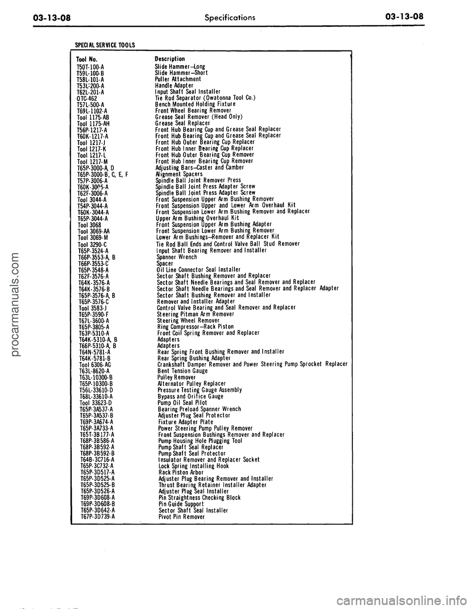
SPECIAL SERVICE TOOLS
Tool No.
T50T-100-A
T59L-100-B
T58L-101-A
T53L-200-A
T62L-201-A
OTC-462
T57L-500-A
T69L-1102-A
Tool 1175-AB
Tool 1175-AH
T56P-1217-A
T60K-1217-A
Tool 1217-J
Tool 1217-K
Tool
1217- L
Tool 1217-M
T65P-3000-A, D
T65P-3000-B, C, E, F
T57P-3006-A
T60K-3005-A
T62F-3006-A
Tool 3044-A
T54P-3044-A
T60K-3044-A
T65P-3044-A
Tool 3068
Tool 3069-AA
Tool
3069-
M
Tool 3290-C
T65P-3524-A
T66P-3553-A, B
T66P-3553-C
T65P-3548-A
T62F-3576-A
T64K-3576-A
T64K-3576-B
T65P-3576-A, B
T65P-3576-C
Tool 3583-J
T65P-3590-F
T67L-3600-A
T65P-3805-A
T63P-5310-A
T64K-5310-A, B
T66P-5310-A, B
T64N-5781-A
T64K-5781-B
Tool 6306-AG
T63L-8620-A
T63L-10300-B
T65P-10300-B
T56L-33610-D
T68L-33610-A
Tool 33623-D
T65P-3A537-A
T65P-3A537-B
T69P-3A674-A
T65P-3A733-A
T65T-3B177-A
T68P-3B586-A
T68P-3B592-A
T68P-3B592-B
T64B-3C716-A
T65P-3C732-A
T65P-3D517-A
T65P-3D525-A
T65P-3D525-B
T65P-3D526-A
T69P-3D608-A
T69P-3D608-B
T65P-3D642-A
T67P-3D739-A
Description
Slide Hammer-Long
Slide Hammer-Short
Puller Attachment
Handle Adapter
Input Shaft Seal Installer
Tie Rod Separator (Owatonna Tool Co.)
Bench Mounted Holding Fixture
Front Wheel Bearing Remover
Grease Seal Remover (Head Only)
Grease Seal Replacer
Front Hub Bearing Cup and Grease Seal Replacer
Front Hub Bearing Cup and Grease Seal Replacer
Front Hub Outer Bearing Cup Replacer
Front Hub Inner Bearing Cup Replacer
Front Hub Outer Bearing Cup Remover
Front Hub Inner Bearing Cup Remover
Adjusting Bars-Caster and Camber
Alignment Spacers
Spindle Ball Joint Remover Press
Spindle Ball Joint Press Adapter Screw
Spindle Ball Joint Press Adapter Screw
Front Suspension Upper Arm Bushing Remover
Front Suspension Upper and Lower Arm Overhaul Kit
Front Suspension Lower Arm Bushing Remover and Replacer
Upper Arm Bushing Overhaul Kit
Front Suspension Upper Arm Bushing Adapter
Front Suspension Lower Arm Bushing Remover
Lower Arm Bushings-Remover and Replacer Kit
Tie Rod Ball Ends and Control Valve Ball Stud Remover
Input Shaft Bearing Remover and Installer
Spanner Wrench
Spacer
Oil Line Connector Seal Installer
Sector Shaft Bushing Remover and Replacer
Sector Shaft Needle Bearings and Seal Remover and Replacer
Sector Shaft Needle Bearings and Seal Remover and Replacer Adapter
Sector Shaft Bushing Remover and Installer
Remover and Installer Adapter
Control Valve Bearing and Seal Remover and Replacer
Steering Pitman Arm Remover
Steering Wheel Remover
Ring Compressor-Rack Piston
Front Coil Spring Remover and Replacer
Adapters
Adapters
Rear Spring Front Bushing Remover and Installer
Rear Spring Bushing Adapter
Crankshaft Damper Remover and Power Steering Pump Sprocket Replacer
Bent Tension Gauge
Pulley Remover
Alternator Pulley Replacer
Pressure Testing Gauge Assembly
Bypass and Orifice Gauge
Pump Oil Seal Pilot
Bearing Preload Spanner Wrench
Adjuster Plug Seal Protector
Fixture Adapter Plate
Power Steering Pump Pulley Remover
Front Suspension Bushings Remover and Replacer
Pump Housing Hole Plugging Tool
Pump Shaft Seal Replacer
Pump Shaft Seal Protector
Insulator Remover and Replacer Socket
Lock Spring Installing Hook
Rack Piston Arbor
Adjuster Plug Bearing Remover and Installer
Thrust Bearing Retainer Installer Adapter
Adjuster Plug Seal Installer
Pin Straightness Checking Block
Pin Guide Support
Sector Shaft Seal Installer
Pivot Pin Removerprocarmanuals.com
Page 198 of 413
04-02-01
Rear Axle
—
Removable Carrier Type
04-02-01
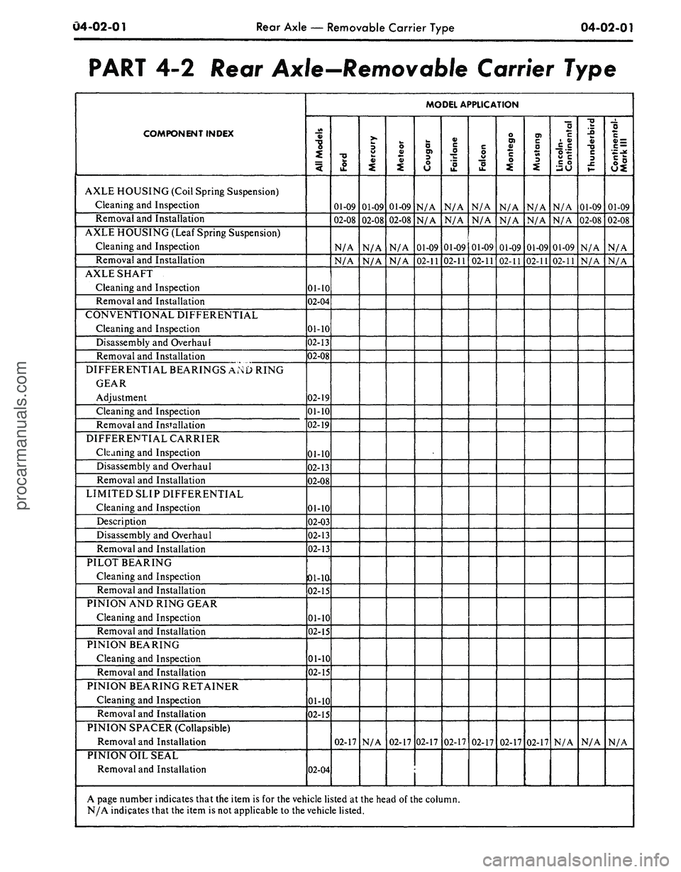
PART
4-2
Rear Axle—Removable Carrier Type
COMPONENT INDEX
AXLE HOUSING (Coil Spring Suspension)
Cleaning and Inspection
Removal and Installation
AXLE HOUSING (Leaf Spring Suspension)
Cleaning and Inspection
Removal and Installation
AXLE SHAFT
Cleaning and Inspection
Removal and Installation
CONVENTIONAL DIFFERENTIAL
Cleaning and Inspection
Disassembly and Overhaul
Removal and Installation
DIFFERENTIAL BEARINGS AND RING
GEAR
Adjustment
Cleaning and Inspection
Removal and Installation
DIFFERENTIAL CARRIER
Cleaning and Inspection
Disassembly and Overhaul
Removal and Installation
LIMITED SLIP DIFFERENTIAL
Cleaning and Inspection
Description
Disassembly and Overhaul
Removal and Installation
PILOT BEARING
Cleaning and Inspection
Removal and Installation
PINION AND RING GEAR
Cleaning and Inspection
Removal and Installation
PINION BEARING
Cleaning and Inspection
Removal and Installation
PINION BEARING RETAINER
Cleaning and Inspection
Removal and Installation
PINION SPACER (Collapsible)
Removal and Installation
PINION OIL SEAL
Removal and Installation
MODEL APPLICATION
All
Models
01-10
02-04
01-10
02-13
02-08
02-19
01-10
02-19
01-10
02-13
02-08
01-10
02-03
02-13
02-13
01-10
02-15
01-10
02-15
01-10
02-15
01-10
02-15
02-04
J
01-09
02-08
N/A
N/A
02-17
Mercury
01-09
02-08
N/A
N/A
N/A
Meteor
01-09
02-08
N/A
N/A
02-17
Cougar
N/A
N/A
01-09
02-11
02-17
Fairlane
N/A
N/A
01-09
02-11
02-17
Falcon
N/A
N/A
01-09
02-11
02-17
Montego
N/A
N/A
01-09
02-11
02-17
Mustang
N/A
N/A
01-09
02-11
02-17
Lincoln-
Continental
N/A
N/A
01-09
02-11
N/A
Thunderbird
01-09
02-08
N/A
N/A
N/A
Continental-
Mark
III
01-09
02-08
N/A
N/A
N/A
A page number indicates that the item is
for
the vehicle listed
at
the head
of
the column.
N/A indicates that the item is not applicable
to
the vehicle listed.
procarmanuals.com
Page 205 of 413
04-02-08
Rear Axle — Removable Carrier Type
04-02-08
REMOVAL AND INSTALLATION
CARRIER ASSEMBLY
REMOVAL
1.
Raise the vehicle on a hoist and
remove the two rear wheels and tires.
2.
Remove the two brake drums (3
Tinnerman nuts at each drum) from
the axle shaft flange studs. If diffi-
culty is experienced in removing the
drums, remove the brake adjuster
knockout slug or rubber plug (if so
equipped) and back off the brake
shoes.
3.
Working through the hole pro-
vided in each axle shaft flange, re-
move the nuts that secure the rear
wheel bearing retainer plate. Pull each
axle shaft assembly out of the axle
housing using axle shaft remover,
Tool 4235-C. (Fig. 4). Care must be
exercised to prevent damage to the
production-type synthetic oil seal, if so
equipped. Any roughing or cutting of
the seal element during removal or in-
stallation can result in early seal fail-
ure.
Install a nut on one of the brake
backing plate attaching bolts to hold
the plate to the axle housing after the
shaft has been removed. Whenever a
rear axle shaft is replaced, the wheel
bearing oil seals must be replaced.
Remove the seals with tool 1175AB.
4.
Make scribe marks on the drive
shaft end yoke and the axle U-joint
flange to insure proper position at as-
sembly. Disconnect the drive shaft at
the rear axle U-joint. Hold the cups
on the spider with tape. Mark the
cups so that they will be in their orig-
inal position relative to the flange
when they are assembled. Remove the
drive shaft from the transmission ex-
tension housing. Install an oil seal re-
placer tool in the housing to prevent
transmission leakage. Refer to the
transmission group for the appropriate
tool.
5.
Clean area around carrier to
housing surfaced with a wire brush and
wipe clean, to prevent dirt entry into
the housing. Place a drain pan under
the carrier and housing, remove the
carrier attaching nuts, and drain the
axle.
Remove the carrier assembly
from the axle housing.
INSTALLATION
Synthetic production-type wheel
bearing seals must not be cleaned,
soaked or washed in cleaning solvent.
1.
Clean the axle housing and
shafts using kerosene and swabs. To
avoid contamination of the grease in
the sealed ball bearings, do not allow
any quantity of solvent directly on the
wheel bearings. Clean the mating sur-
faces of the axle housing and carrier.
2.
Position the differential carrier
on the studs in the axle housing using
a new gasket between carrier and
housing. Install the carrier-to-housing
attaching nuts, and torque them to
specifications.
3.
Remove the oil seal replacer tool
from the transmission extension hous-
ing. Position the drive shaft so that
the front U-joint slip yoke splines to
the transmission output shaft.
4.
Connect the drive shaft to the
axle U-joint flange, aligning the scribe
marks made on the drive shaft end
yoke and the axle U-joint flange dur-
ing the removal procedure. Install the
U-bolts and nuts and torque to speci-
fications.
5.
If the synthetic, production-type
wheel bearing seals were replaced with
service-type leather seals, soak the
new rear wheel bearing oil seals in
SAE 10 oil for 1/2 hour before instal-
lation. Wipe a small amount of an oil
resistant sealer on the outer edge of
each seal before it is installed. Do not
put any of the sealer on the sealing
lip.
Install the oil seals in the ends of
the rear axle housing with one of the
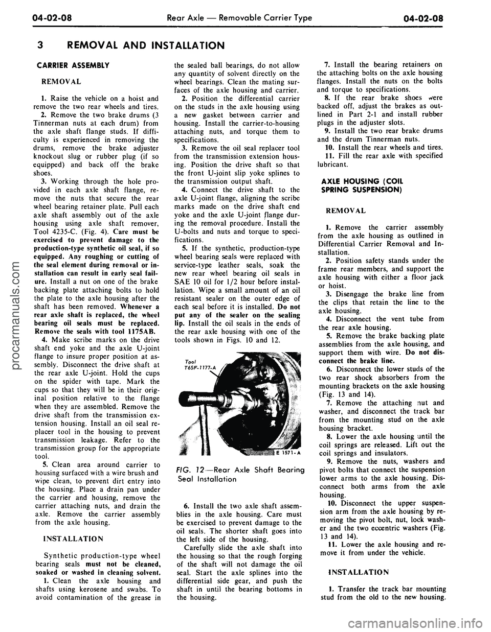
tools shown in Figs. 10 and 12.
Tool
T65F-1177.A
E 1571-A
FIG. 12—Rear Axle Shaft Bearing
Seal Installation
6. Install the two axle shaft assem-
blies in the axle housing. Care must
be exercised to prevent damage to the
oil seals. The shorter shaft goes into
the left side of the housing.
Carefully slide the axle shaft into
the housing so that the rough forging
of the shaft will not damage the oil
seal. Start the axle splines into the
differential side gear, and push the
shaft in until the bearing bottoms in
the housing.
7.
Install the bearing retainers on
the attaching bolts on the axle housing
flanges. Install the nuts on the bolts
and torque to specifications.
8. If the rear brake shoes were
backed off, adjust the brakes as out-
lined in Part 2-1 and install rubber
plugs in the adjuster slots.
9. Install the two rear brake drums
and the drum Tinnerman nuts.
10.
Install the rear wheels and tires.
11.
Fill the rear axle with specified
lubricant.
AXLE HOUSING (COIL
SPRING SUSPENSION)
REMOVAL
1.
Remove the carrier assembly
from the axle housing as outlined in
Differential Carrier Removal and In-
stallation.
2.
Position safety stands under the
frame rear members, and support the
axle housing with either a floor jack
or hoist.
3.
Disengage the brake line from
the clips that retain the line to the
axle housing.
4.
Disconnect the vent tube from
the rear axle housing.
5.
Remove the brake backing plate
assemblies from the axle housing, and
support them with wire. Do not dis-
connect the brake line.
6. Disconnect the lower studs of the
two rear shock absorbers from the
mounting brackets on the axle housing
(Fig. 13 and 14).
7.
Remove the attaching nut and
washer, and disconnect the track bar
from the mounting stud on the axle
housing bracket.
8. Lower the axle housing until the
coil springs are released. Lift out the
coil springs and insulators.
9. Remove the nuts, washers and
pivot bolts that connect the suspension
lower arms to the axle housing. Dis-
connect both arms from the axle
housing.
10.
Disconnect the upper suspen-
sion arm from the axle housing by re-
moving the pivot bolt, nut, lock wash-
er and the two eccentric washers (Fig.
13 and 14).
11.
Lower the axle housing and re-
move it from under the vehicle.
INSTALLATION
1.
Transfer the track bar mounting
stud from the old to the new housing.procarmanuals.com
Page 206 of 413
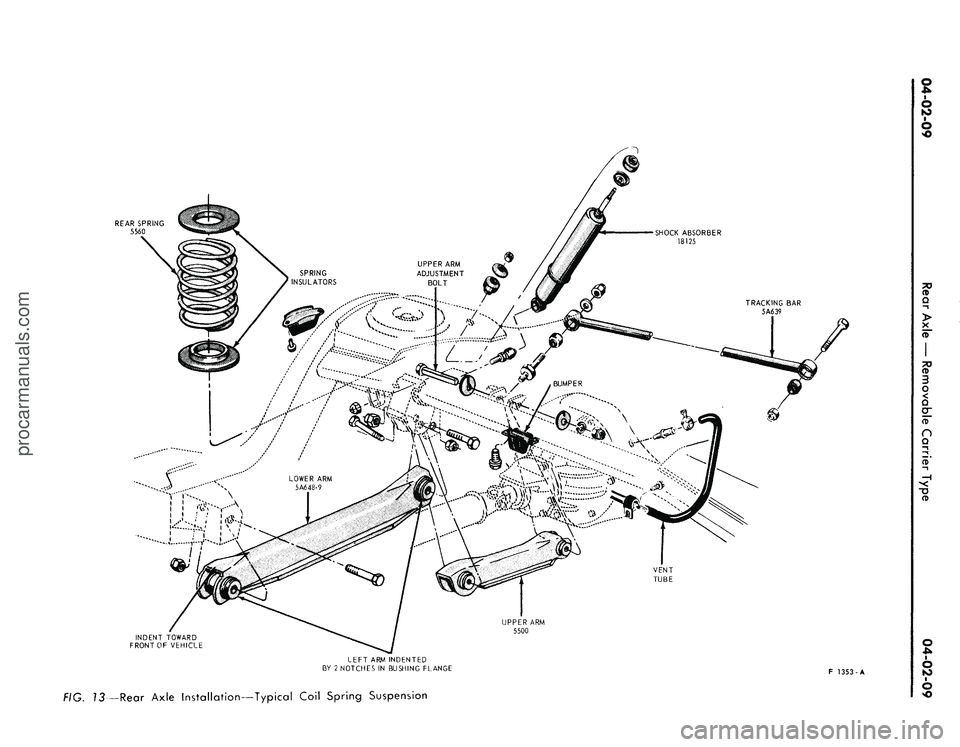
REAR SPRING
5560
VENT
TUBE
INDENT TOWARD
FRONT OF VEHICLE
UPPER ARM
5500
LEFT ARM INDENTED
BY 2 NOTCHES IN BUSHING FLANGE
F 1353-A
f/Q.
J3—Rear Axle Installation—Typical Coil Spring Suspensionprocarmanuals.com
Page 208 of 413
04-02-11
Rear Axle — Removable Carrier Type
04-02-11
If the axle housing is new, install a
new vent. The hose attaching portion
must face toward the front of the ve-
hicle.
2.
If leather-type wheel bearing ser-
vice seals are to be installed, soak the
new rear wheel bearing oil seals in
SAE 10 oil for 1/2 hour before instal-
lation. Wipe a small amount of an oil
resistant sealer on the outer edge of
each seal before it is installed. Do not
put any of the sealer on the sealing
lip.
Install the oil seals in the ends of
the axle housing with one of the tools
shown in Fig. 10 and 12.
3.
Position the replacement axle
housing under the vehicle, and raise
the axle with a hoist or floor jack.
Connect the suspension lower arms to
their mounting brackets on the axle
housing with pivot bolts and nuts. Do
not tighten the bolts and nuts at this
point.
4.
Position the suspension upper
arm in its mounting bracket on the
axle housing, and install the adjusting
bolt, eccentric washers, lock washer
and nut. Leave the bolt and nut loose
at this point.
5.
Position the brake lines to the
axle housing, and secure with the re-
taining clips.
6. Install the brake backing plates
on the axle housing flanges.
7.
Connect the track bar to the
mounting stud, install the washer and
attaching nut, and torque to specifica-
tions.
8. Position the rear coil springs and
insulators in the pockets provided.
9. Connect the lower studs of the
two rear shock absorbers to the
mounting brackets on the axle hous-
ing. Install the attaching nuts, and
torque to specifications.
10.
Connect the vent tube to the
vent on the housing. If axle housing is
new, install a new vent.
11.
Clean the mating surfaces of
the axle housing and differential car-
rier. Position the carrier on the
mounting studs on the housing using a
new gasket between carrier and hous-
ing. Install the copper washers and the
carrier-to-housing attaching nuts, and
torque to specifications.
12.
Make sure that both the front
and rear pivot bolts of the upper and
the two lower arms are loose, and
then raise the axle assembly to con-
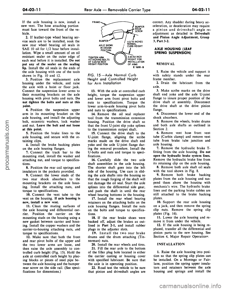
trolled curb height (Fig. 15). Hold the
axle at controlled curb height by plac-
ing blocks or pieces of steel pipe be-
tween the axle housing and the bumper
rear screw on the side rail. (See speci-
fications for dimensions.)
FRAME
TIGHTEN ARM
ATTACHING BOLTS
AT 5-45/64 INCH
HEIGHT POSITION
5-45/64 INCH
HEIGHT FOR
INSTALLATION
OF ARMS
E 1600-B
FIG. 75 -Axle Normal Curb
Height and Controlled Height
for Arm Installation
13.
With the axle at controlled curb
height, torque the suspension upper
and lower arm front pivot bolts and
nuts to specifications. Torque the
lower arm-to-axle housing pivot bolts
and nuts to specifications.
14.
Remove the oil seal replacer
tool from the transmission extension
housing. Position the drive shaft so
that the front U-joint slip yoke splines
to the transmission output shaft.
15.
Connect the drive shaft to the
U-joint flange, aligning the scribe
marks made on the drive shaft end
yoke and the axle U-joint flange dur-
ing the removal procedure. Install the
U-bolts and nuts and torque to speci-
fications.
16.
Carefully slide the two axle
shaft assemblies in the axle housing.
The shorter shaft goes into the left
side of the housing. Use care in slid-
ing the axle shafts into the housing so
that the rough forging of the shaft will
not damage the oil seal. Start the axle
splines into the differential side gear,
and push the shaft in until the rear
wheel bearing bottoms in the housing.
17.
Install the rear wheel bearing
retainers on the attaching bolts on the
axle housing flanges. Install the nuts
on the bolts and torque to specifica-
tions.
18.
If the rear brake shoes were
backed off, adjust the brakes as out-
lined in Part 2-1, and install rubber
plugs in the adjuster slots.
19.
Install the two rear brake
drums and the drum attaching (Tin-
nerman) nuts.
20.
Install the rear wheels and tires.
21.
Fill the rear axle to the bottom
of the filler plug hole located in either
the carrier casting or housing cover
with specified lubricant. Be sure that
the axle is in operating position.
22.
Road test the vehicle to be sure
that pinion and driveshaft angles are
correct. Any shudder during heavy ac-
celeration, or deceleration may require
a pinion and driveshaft angle re-
adjustment as detailed in Driveshaft
and Pinion Angle Adjustment, Group
3,
Part 3-2.
AXLE HOUSING (LEAF
SPRING SUSPENSION)
REMOVAL
1.
Raise the vehicle and support it
with safety stands under the rear
frame member.
2.
Drain the lubricant from the
axle.
3.
Make scribe marks on the drive
shaft end yoke and the axle U-joint
flange to insure proper position of the
drive shaft at assembly. Disconnect
the drive shaft at the drive pinion
flange.
4.
Disconnect the lower end of the
shock absorbers.
5.
Remove the wheels, brake drums
and both axle shafts as outlined in
Section 2.
6. Remove vent hose front vent
tube (Corbin clamp) and remove vent
tube from brake tube junction and
axle housing.
7.
Remove the hydraulic brake T-
fitting from the axle housing. Do not
open the hydraulic brake system lines.
Remove the hydraulic brake line from
its retaining clip on the axle housing.
8. Remove both axle shaft oil seals
with the tool shown in Fig. 8.
9. Remove both brake backing
plates from the axle housing and sus-
pend them above the housing with
mechanic's wire. The hydraulic brake
lines and the parking brake cables are
still attached to the brake backing
plates.
10.
Support the rear axle housing
on a jack, and then remove the spring
clip nuts. Remove the spring clip
plates (Fig. 16).
11.
Lower the axle housing and re-
move it from under the vehicle.
12.
If the axle housing is being re-
placed, transfer all the differential and
pinion parts to the new housing. See
Section 4, Major Repair Operation*.
INSTALLATION
1.
Raise the axle housing into posi-
tion so that the spring clip plates can
be installed. On a Montego or Fair-
lane,
position the spring upper insula-
tors and retainers between the axle
housing and springs and install theprocarmanuals.com
Page 235 of 413
04-04-04
Rear Axle — Ford Light-Duty (WER)
04-04-04
REMOVAL AND INSTALLATION
AXLE HOUSING
Refer to Fig. 7.
REMOVAL
1.
Raise the vehicle on a hoist.
2.
Remove the wheels and tires
from the brake drums.
3.
Position a drain pan and loosen
the rear axle cover to housing attach-
ing bolts. Drain the housing.
4.
Remove the attaching (Tinner-
man) nuts that secure the brake drums
to the axle shaft flanges, and then re-
move the drums (Fig. 7).
5.
Remove the axle housing cover
bolts,
cover and gasket. Discard the
gasket. Remove the drain pan.
6. Disconnect the drive shaft at the
drive pinion companion flange. Re-
move the drive shaft from the trans-
mission extension housing. Install an
oil seal replacer tool in the transmis-
sion housing to prevent leakage. Refer
to the transmission group for the ap-
propriate tool.
7.
Disconnect the lower end of the
shock absorbers at the mounting
brackets.
8. Disconnect the track bar from
the axle housing stud. If the axle
housing is to be replaced, transfer the
stud to the new housing.
9. Position safety stands under the
rear frame members. Lower the vehi-
cle with the hoist and allow the axle
to lower far enough to relieve rear
spring tension.
10.
Remove the pinion shaft lock
bolt and pinion shaft (Fig. 2), differ-
ential pinion gears and thrust washers.
11.
Push the axle shaft(s) inward
toward the center of the axle housing.
Remove the C-locks from the inner
ends of the axles (Fig. 3). Remove the
axle shafts from the housing. Extreme
care must be used to avoid contacting
the axle shaft seal lip with any portion
of the axle shaft other than the seal
journal.
12.
Disconnect the vent hose from
the rear vent tube and remove all
brake lines from the axle housing re-
taining clips.
13.
Remove the brake backing
plate attaching nuts and the plates
from the axle housing. Suspend the
plates above the axle housing with
mechanics wire. The hydraulic brake
lines and the parking brake cables will
remain attached to the brake backing
plates.
14.
Support the rear axle housine
on a jack.
15.
Remove the right and left rear
springs and insulators.
16.
Remove the nuts, washers and
pivot bolts that connect the suspension
lower arms to the axle housing. Dis-
connect both arms from the axle
housing.
17.
Disconnect the upper suspen-
sion arm from the axle housing by re-
moving the pivot bolt, nut, lock wash-
er and two eccentric washers.
18.
Lower the rear axle to the floor
with the jack and remove the axle
from under the vehicle.
19.
Remove the wheel bearings and
oil seals with the tool shown in Fig. 4.
20.
If the axle housing is being re-
placed, transfer all the differential and
pinion parts to the new housing. Refer
to Section 4, Major Repair Operation
for the procedure.
INSTALLATION
1.
Lightly coat the wheel bearing
rollers with axle lubricant. Install
wheel bearings in the axle housing
with the tool shown in Fig. 5. The
bearings should seat firmly against the
shoulder.
2.
Wipe all lubricant from the oil
seal bore before installing the seal. If
axle housing is being replaced, new
seals must be installed.
3.
Inspect the original seal for
nicks,
scuffs or abnormal wear, and
replace if necessary. New seals are
pre-packed with lubricant and do not
require an oil soak.
4.
Install the seal with the tool
shown in Fig. 6. Installation without
the use of the proper tool will distort
the seal and cause leakage.
5. Raise the rear axle into position
under the vehicle with a hoist or floor
jack. Connect the suspension lower
arms to their mounting brackets on
the axle housing with pivot bolts and
nuts.
Do not tighten the mounting
bolts at this point.
6. Position the suspension upper
arm in its mounting bracket on the
axle housing and install the adjusting
bolt, eccentric washers, lock washer
and nut. Do not tighten the mounting
bolt at this point.
7.
Place the rear coil springs and
insulators into position in the pockets
provided.
8. Place the brake backing plates
on the axle housing flanges, install 4
attaching bolts and nuts and torque
them to specifications.
9. Position the brake lines to the
axle housing and secure them with the
retaining clips. If the axle housing is
new, install a new vent. When install-
ing the new axle vent apply a small
amount of Locktite (C5AZ-19554-B)
to prevent oil leakage between vent
and axle housing. Connect the vent
tube to the vent.
10.
Install the pinion side gears and
thrust washer.
11.
Slide the axle shafts into place
in the axle housing. Exercise care that
splines or any portion of the axle
shafts do not damage the oil seals and
that they engage with the splines of
the differential side gears.
12.
Install the axle shaft C-lock O-
ring and C-lock on the inner end of
the shaft and push the shaft outward
so that the shaft lock seats in the
counterbore of the differential side
gear.
13.
Position the pinion differential
gears and thrust washers 180 degrees
apart to the differential side gears.
Revolve the gear assembly until the
holes in the differential case are al-
igned with the pinion gears.
14.
Position the differential pinion
shaft through the case and pinions, al-
igning the hole in the shaft with the
lock bolt hole. Install the lock bolt
and tighten it to specification.
15.
Clean the gasket mounting sur-
face of the rear axle housing and the
cover. Install a new cover gasket,
cover and the attaching bolts. Torque
the bolts to specification.
16.
Raise the rear axle on a hoist
and remove the safety stands.
17.
Connect the track bar to the
mounting stud. Install the washer and
nut. Torque the nut to specification.
18.
Connect the two rear shock ab-
sorbers to the mounting brackets on
the axle housing and torque the at-
taching nuts to specification.
19.
Make sure that both the front
and rear pivot bolts of the upper and
the two lower arms are loose, then
raise the axle assembly to the con-
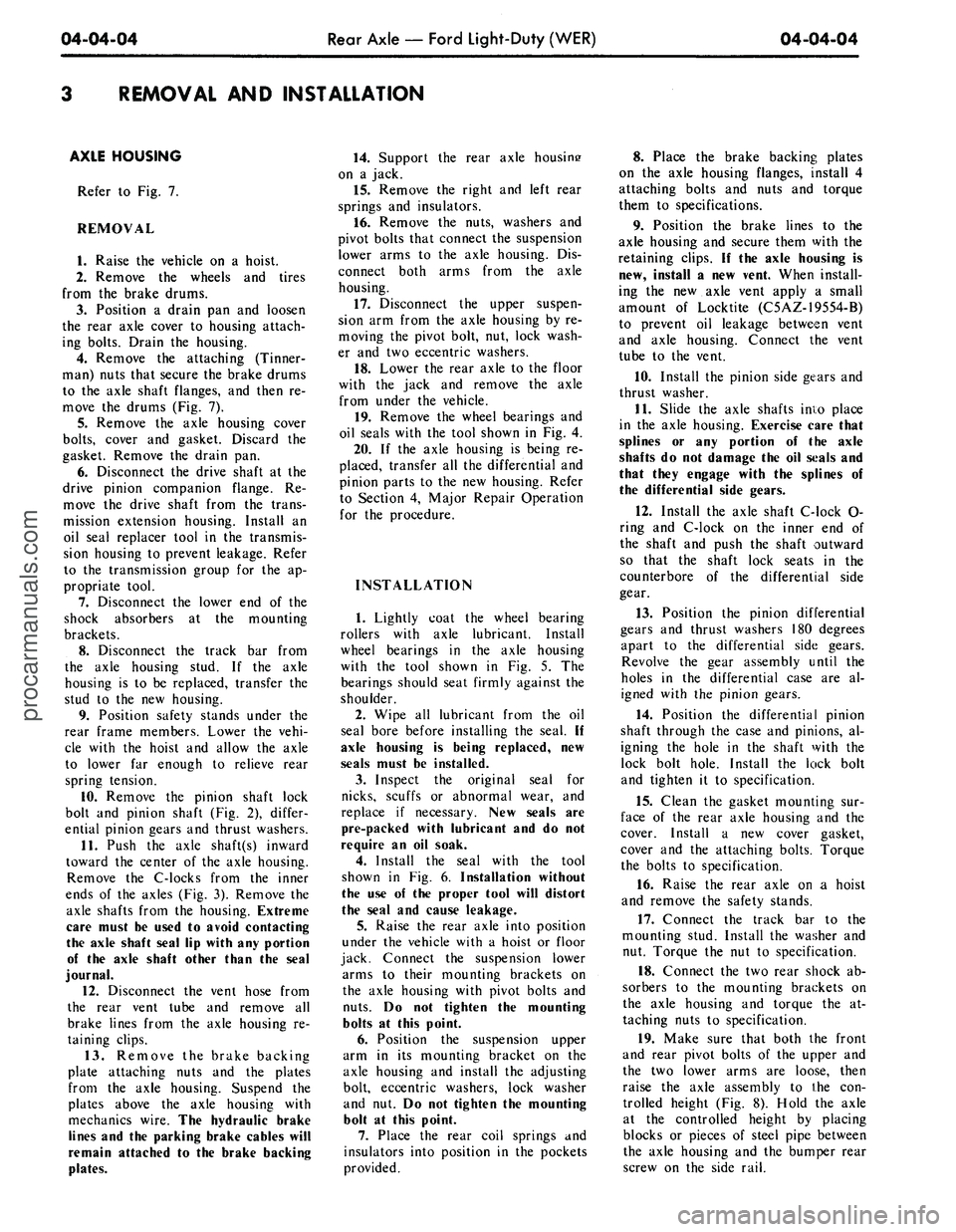
trolled height (Fig. 8). Hold the axle
at the controlled height by placing
blocks or pieces of steel pipe between
the axle housing and the bumper rear
screw on the side rail.procarmanuals.com
Page 237 of 413
04-04-06
Rear Axle — Ford Light-Duty (WER)
04-04-06
20.
With the axle at controlled
height, torque the suspension upper
and lower arm front pivot bolts and
nuts to specifications. Torque the
lower arm to axle housing pivot bolts
and nuts to specifications.
21.
Remove the oil seal replacer
from the transmission extension hous-
ing. Install the drive shaft in the ex-
tension housing. Align the scribe
marks on the cups, flange and drive
shaft and connect the drive shaft at
the drive pinion flange. Torque the at-
taching bolts to specification
FRAME
TIGHTEN ARM
ATTACHING BOLTS
AT 5-45/64 INCH
HEIGHT POSITION
5-45/64 INCH
HEIGHT FOR
INSTALLATION
OF ARMS
E 1600-B
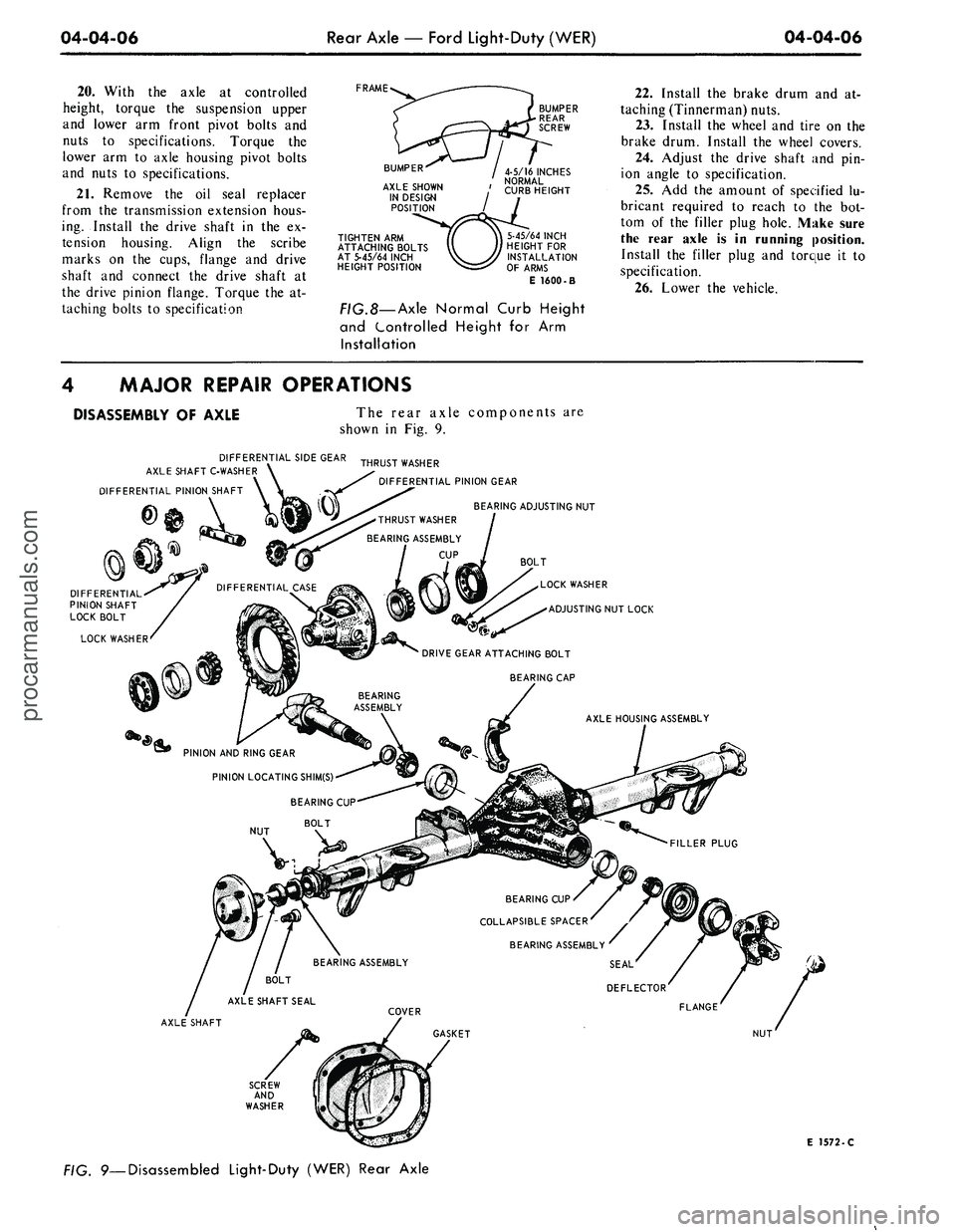
FIG.8—
Axle
Normal Curb Height
and Controlled Height for Arm
Installation
22.
Install the brake drum and at-
taching (Tinnerman) nuts.
23.
Install the wheel and tire on the
brake drum. Install the wheel covers.
24.
Adjust the drive shaft and pin-
ion angle to specification.
25.
Add the amount of specified lu-
bricant required to reach to the bot-
tom of the filler plug hole. Make sure
the rear axle is in running position.
Install the filler plug and torque it to
specification.
26.
Lower the vehicle.
4 MAJOR REPAIR OPERATIONS
DISASSEMBLY OF AXLE
The rear axle components are
shown in Fig. 9.
DIFFERENTIAL SIDE GEAR
AXLE SHAFT C-WASHER \
DIFFERENTIAL PINION SHAFT
THRUST WASHER
BEARING ASSEMBLY
CUP
THRUST WASHER
^^ DIFFERENTIAL PINION GEAR
BEARING ADJUSTING NUT
DIFFERENTIAL
PINION SHAFT
LOCK BOLT
LOCK WASHER
BOLT
LOCK WASHER
ADJUSTING NUT LOCK
DRIVE GEAR ATTACHING BOLT
BEARING CAP
AXLE HOUSING ASSEMBLY
PINION AND RING GEAR
PINION LOCATING SHIM(S)
BEARING CUP
BOLT
NUT
BEARING CUP
COLLAPSIBLE SPACER
AXLE SHAFT
E 1572-C
FIG. 9—Disassembled Light-Duty (WER) Rear Axleprocarmanuals.com
Page 246 of 413
04-05-05
Specifications
04-05-05
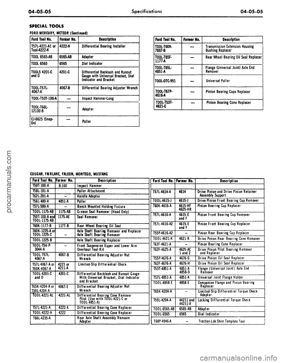
SPECIAL TOOLS
FORD MERCURY, METEOR (Continued)
Ford Tool No.
T57L-4221-A1 or
Tool-4222-K
TOOL 6565-AB
TOOL 6565
TOOLS 4201-C
andD
TOOL-T57L-
4067-A
TOOL-T50T-100-A
T00L-T66L-
12132-B
CJ-6625 (Snap-
On)
Foniisr
NO.
4222-H
6565-AB
6565
4201-C
4067-B
—
—
—
Description
Differential Bearing Installer
Adapter
Dial Indicator
Differential Backlash and Runout
Gauge with Universal Bracket, Dial
Indicator and Bracket
Differential Bearing Adjuster Wrench
Impact Hammer-Long
Adapter
Puller
Ford Tool No.
TOOL-T60K-
7697-B
T00L-T65F-
1177-A
T00L-T65L-
4851-A
TOOL-OTC-951
T00L-T67P-
4616-A
TOOL-T53T-
4621-C
Fomor No.
—
—
—
—
—
Description
Transmission Extension Housing
Bushing Repiacer
Rear Wheel Bearing Oil Seal Repiacer
Flange (Universal Joint) Axle End
Remover
Universal Puller
Pinion Bearing Cups Repiacer
Pinion Bearing Cone Repiacer
COUGAR, FAIRLANE, FALCON,
Ford Tool No.
T50T-100-A
T58L-101-A
T62L-201-A
T56L-400-A
T57L-500-A
T00L-1175-AB
T50T-100-Aand
TOOL-1175-AB
T60K-1177-B
T60K-1225-Aor
T00L-1225-C
TOOL-1225-B
T00L-T54-P-
3044-A
T00L-T57L-
4067-A
T57L-4067-Aor
T60K-4067-A
TOOL-4201-C
andD
T65K-4204A or
T59L-4204-A
T00L-4221-AL
T57L-4221-A
T00L-4222-H
T66L-4235-A
Former No.
B-160
-
4851-A
-
1175-AB
1175-AE
1177-B
4067-B
4221 or
4211-A
4201-C
4067-E
4221-AL
4222-K
4222
MONTEGO, MUSTANG
Description
Impact Hammer
Puller Attachment
Handle Adapter
Puller
Bench Mounted Holding Fixture
Grease Seal Remover (Head Only)
Seal Remover
Rear Wheel Bearing Oil Seal
Axle Shaft Bearing Remover and Repiacer
Axle Shaft Searing Remover
Axle Shaft Bearing Repiacer
Front Suspension Upper and Lower Arm
Overhaul Tool Kit
Differential Bearing Adjuster Nut
Wrench
Limited-Slip Differential Check
Differential Backlash and Runout Gauge
With Universal Bracket, Dial Indicator
and Bracket
Differential Bearing Adjuster Nut
Wrench
Differential Bearing Cone Remover
Pilot (Use with T00L-4221C or
T00L-4851-A)
Differential Bearing Cone Repiacer
Differential Bearing Cone Repiacer
Rear Axle Shaft Assembly Remover
Adapter
Ford Tool No.
T57L-4614-A
T00L-4615-J
T60K-4616-A
T57L-4616-A
T57L-4616-A2
T55P-4616-A2
T00L-4621-K
T62F-4621A
T62F-4625-A
T55P-4676-A
T62F4676A
T53T-4851A
T57L-4851-A
T00L-4858-E
T65K-4204-A
T59L-4204-A
T00L-6565-AB
TOOL-6565
Former No.
4614
4615-J
4615-HF
4625-HR
4615-
E
andP
4615-
E
andF
-
4621-K
4625-AC
land 2
4676-G
4676-
H
4851-A
4858-D
4851-K
4858-
E
—
44211 and
44211-A
6565-AB
6565
Description
Drive Pinion and Drive Pinion Retainer
Assembly Support
Drive Pinion Front Bearing Cup Remover
Pinion Bearing Cup Repiacer
Pinion Front Bearing Cup Remover
Pinion Front Bearing Cup Repiacer
Pinion Rear Bearing Cup Repiacer
Drive Pinion Rear Bearing Cone Remover
Pinion Bearing Cone Repiacer
Drive Pinion Pilot Bearing Remover
and Repiacer
Drive Pinion Oil Seal Repiacer
Drive Pinion Oil Seal Repiacer
Flange (Universal Joint) Axle End
Remover
Universal Joint Flange Holder
Companion Flange and Pinion Bearing
Repiacer
Limited-Slip Differential Torque Check
Adapter
Locking Differential Torque Check
Adapter
Dial Indicator
T68P-4946-A - Traction-Lok Shim Template Toolprocarmanuals.com