ABS FORD MUSTANG 1969 Volume One Chassis
[x] Cancel search | Manufacturer: FORD, Model Year: 1969, Model line: MUSTANG, Model: FORD MUSTANG 1969Pages: 413, PDF Size: 75.81 MB
Page 24 of 413
02-02-05
Brake System
02-02-05
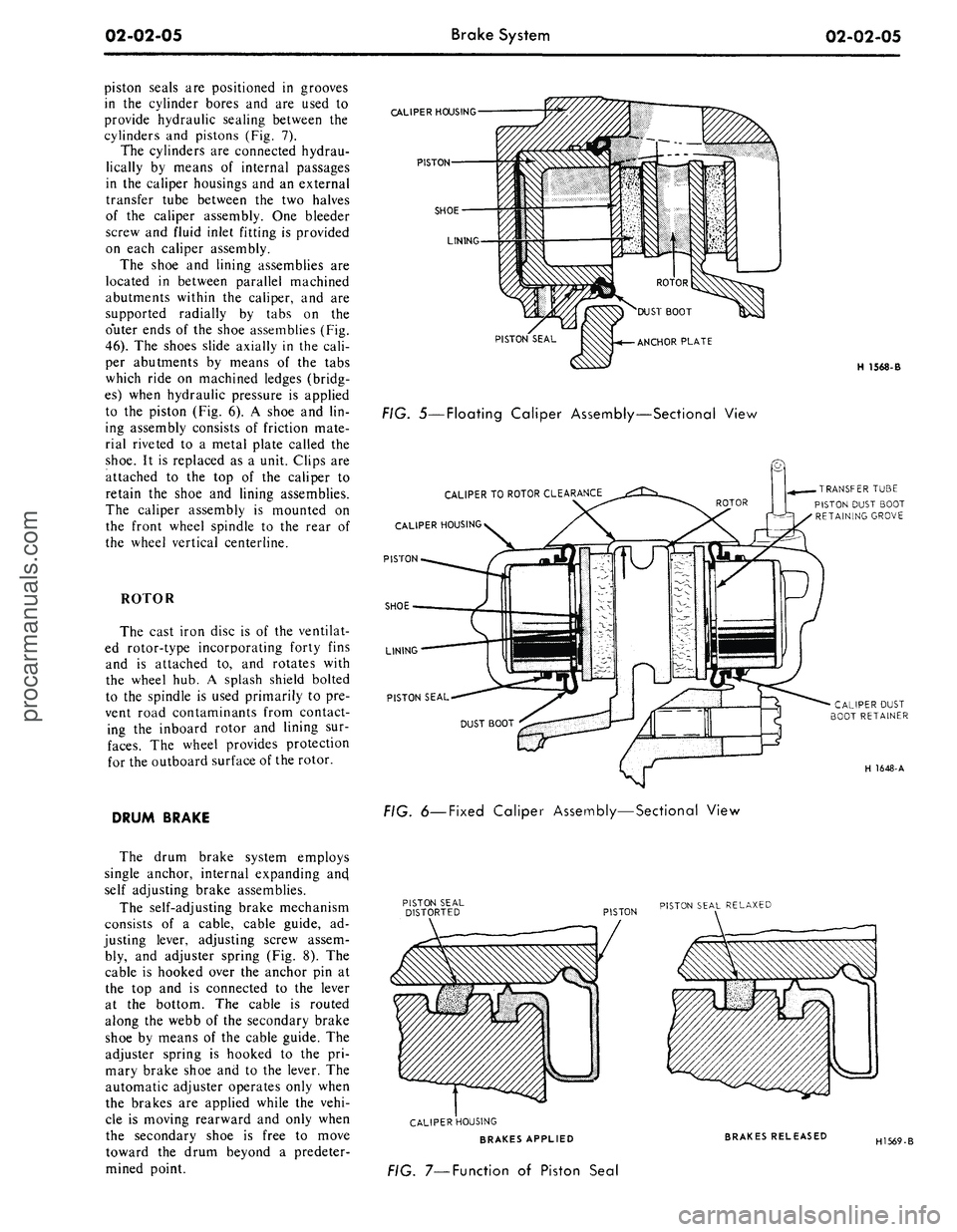
piston seals are positioned in grooves
in the cylinder bores and are used to
provide hydraulic sealing between the
cylinders and pistons (Fig. 7).
The cylinders are connected hydrau-
lically by means of internal passages
in the caliper housings and an external
transfer tube between the two halves
of the caliper assembly. One bleeder
screw and fluid inlet fitting is provided
on each caliper assembly.
The shoe and lining assemblies are
located in between parallel machined
abutments within the caliper, and are
supported radially by tabs on the
o'uter ends of the shoe assemblies (Fig.
46).
The shoes slide axially in the cali-
per abutments by means of the tabs
which ride on machined ledges (bridg-
es) when hydraulic pressure is applied
to the piston (Fig. 6). A shoe and lin-
ing assembly consists of friction mate-
rial riveted to a metal plate called the
shoe.
It is replaced as a unit. Clips are
attached to the top of the caliper to
retain the shoe and lining assemblies.
The caliper assembly is mounted on
the front wheel spindle to the rear of
the wheel vertical centerline.
ROTOR
The cast iron disc is of the ventilat-
ed rotor-type incorporating forty fins
and is attached to, and rotates with
the wheel hub. A splash shield bolted
to the spindle is used primarily to pre-
vent road contaminants from contact-
ing the inboard rotor and lining sur-
faces.
The wheel provides protection
for the outboard surface of the rotor.
DRUM BRAKE
The drum brake system employs
single anchor, internal expanding ancj
self adjusting brake assemblies.
The self-adjusting brake mechanism
consists of a cable, cable guide, ad-
justing lever, adjusting screw assem-
bly, and adjuster spring (Fig. 8). The
cable is hooked over the anchor pin at
the top and is connected to the lever
at the bottom. The cable is routed
along the webb of the secondary brake
shoe by means of the cable guide. The
adjuster spring is hooked to the pri-
mary brake shoe and to the lever. The
automatic adjuster operates only when
the brakes are applied while the vehi-
cle is moving rearward and only when
the secondary shoe is free to move
toward the drum beyond a predeter-
mined point.
CALIPER
HOUSING
PISTON
SHOE
LINING
PISTON SEAL
FIG. 5—Floating Caliper Assembly—Sectional View
CALIPER
TO
ROTOR
CLEARANCE
CALIPER
HOUSING
PISTON
SHOE
LINING
PISTON SEAL
H 1568-B
TRANSFER
TUBE
PISTON DUST BOOT
RETAINING
GROVE
CALIPER
DUST
BOOT
RETAINER
H 1648-A
FIG.
6—Fixed
Caliper Assembly—Sectional View
PISTON
PISTON SEAL
RELAXED
CALIPER
HOUSING
BRAKES APPLIED
FIG. 7—Function of Piston Seal
BRAKES RELEASED
H1569-Bprocarmanuals.com
Page 27 of 413
02-02-08
Brake System
02-02-08
Tool-HRE-8650
JUST SET TO DRUM
DIAMETER HERE . . .
FIND CORRECT BRAKE
SHOE DIAMETER HERE
H1416-A
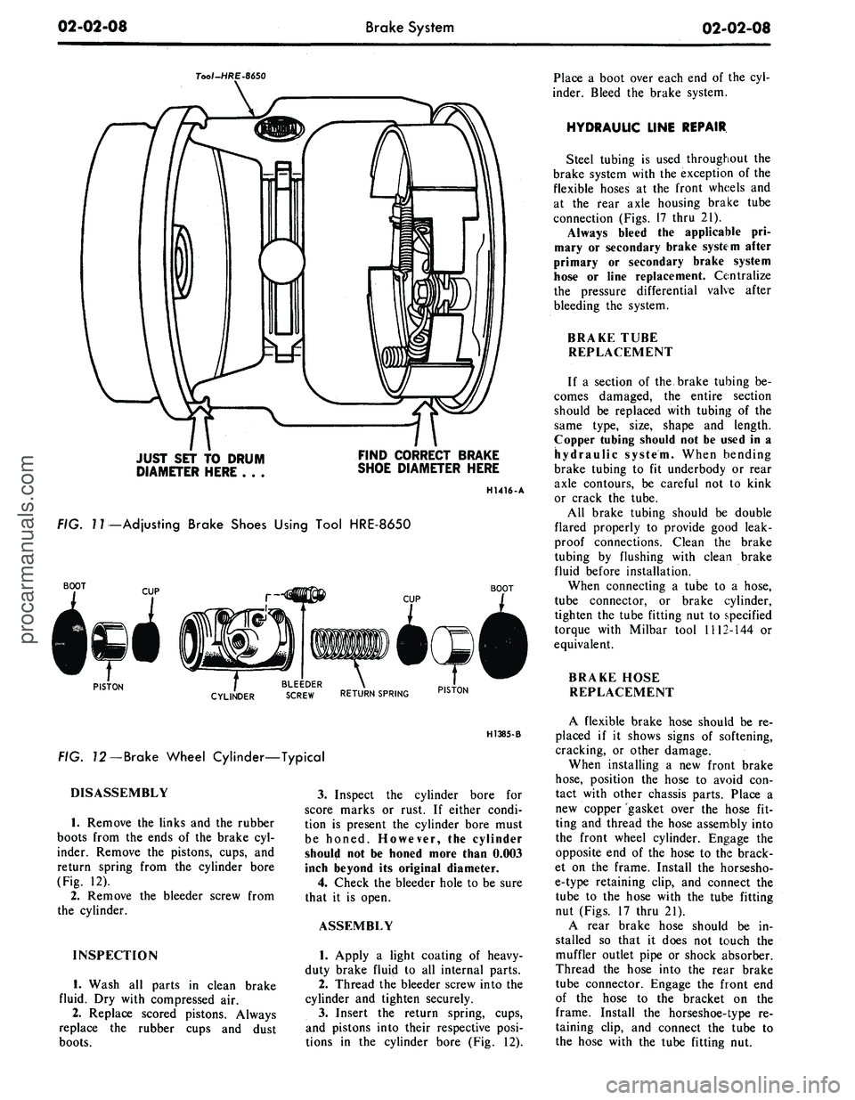
FIG.
7
7—Adjusting Brake Shoes Using Tool HRE-8650
BOOT
BOOT
PISTON
. BLEEDER .
CYLINDER
SCREW RETURN SPRING PIST0N
H1385-B
FIG. 72—Brake Wheel Cylinder—Typical
DISASSEMBLY
1.
Remove the links and the rubber
boots from the ends of the brake cyl-
inder. Remove the pistons, cups, and
return spring from the cylinder bore
(Fig. 12).
2.
Remove the bleeder screw from
the cylinder.
INSPECTION
1.
Wash all parts in clean brake
fluid. Dry with compressed air.
2.
Replace scored pistons. Always
replace the rubber cups and dust
boots.
3.
Inspect the cylinder bore for
score marks or rust. If either condi-
tion is present the cylinder bore must
be honed. However, the cylinder
should not be honed more than 0.003
inch beyond its original diameter.
4.
Check the bleeder hole to be sure
that it is open.
ASSEMBLY
1.
Apply a light coating of heavy-
duty brake fluip! to all internal parts.
2.
Thread the bleeder screw into the
cylinder and tighten securely.
3.
Insert the return spring, cups,
and pistons into their respective posi-
tions in the cylinder bore (Fig. 12).
Place a boot over each end of the cyl-
inder. Bleed the brake system.
HYDRAULIC LINE REPAIR
Steel tubing is used throughout the
brake system with the exception of the
flexible hoses at the front wheels and
at the fear axle housing brake tube
connection (Figs. 17 thru 21).
Always bleed the applicable pri-
mary or secondary brake system after
primary or secondary brake system
hose or line replacement. Centralize
the pressure differential valve after
bleeding the system.
BRAKE TUBE
REPLACEMENT
If a section of the brake tubing be-
comes damaged, the entire section
should be replaced with tubing of the
same type, size, shape and length.
Copper tubing should not be used in a
hydraulic system. When bending
brake tubing to fit underbody or rear
axle contours, be careful not to kink
or crack the tube.
All brake tubing should be double
flared properly to provide good leak-
proof connections. Clean the brake
tubing by flushing with clean brake
fluid before installation.
When connecting a tube to a hose,
tube connector, or brake cylinder,
tighten the tube fitting nut to specified
torque with Milbar tool 1112-144 or
equivalent.
BRAKE HOSE
REPLACEMENT
A flexible brake hose should be re-
placed if it shows signs of softening,
cracking, or other damage.
When installing a new front brake
hose,
position the hose to avoid con-
tact with other chassis parts. Place a
new copper gasket over the hose fit-
ting and thread the hose assembly into
the front wheel cylinder. Engage the
opposite end of the hose to the brack-
et on the frame. Install the horsesho-
e-type retaining clip, and connect the
tube to the hose with the tube fitting
nut (Figs. 17 thru 21).
A rear brake hose should be in-
stalled so that it does not touch the
muffler outlet pipe or shock absorber.
Thread the hose into the rear brake
tube connector. Engage the front end
of the hose to the bracket on the
frame. Install the horseshoe-type re-
taining clip, and connect the tube to
the hose with the tube fitting nut.procarmanuals.com
Page 38 of 413
02-02-19
Brake System
02-02-19
that the tabs on the shoe flanges seat
fully against the caliper bridges (Fig.
25).
2.
Install the caliper splash shield
and secure the shield to the caliper
with two retaining bolts (Fig. 4).
3.
Pump the brake pedal several
times until a firm pedal is obtained
and the shoe and lining assemblies are
properly seated.
4.
Install the wheel and tire assem-
bly on the hub and rotor assembly.
5.
Check and refill the master cyl-
inder reservoir with specified brake
fluid as required.
6. Road test the car.
It should not be necessary to bleed
the system after a shoe and lining re-
placement.
FRONT WHEEL HUB AND
ROTOR ASSEMBLY-
DISC BRAKES
REMOVAL
1.
Remove the wheel and tire from
the hub (Figs. 23 and 24). Be careful
to avoid damage or interference with
the bleeder screw fitting. On Lincoln
Continental models be careful to avoid
damage to the caliper splash shield or
transfer tube.
2.
Remove the caliper assembly
from the spindle and the rotor. If the
caliper does not require servicing, it is
not necessary to disconnect the brake
hose or remove the caliper from the
vehicle. Position the caliper out of the
way, and support it with a wire to
avoid damaging the caliper or stretch-
ing the hose. Insert a clean cardboard
spacer between the linings to prevent
the piston from coming out of the cyl-
inder bore while the caliper is re-
moved.
Handle the rotor and caliper assem-
blies in such a way as to avoid defor-
mation of the rotor and nicking,
scratching or contamination of the
brake linings.
3.
Remove the grease cap from the
hub.
Remove the cotter pin, nut lock,
adjusting nut, and flat washer from
the spindle. Remove the outer bearing
cone and roller assembly.
4.
Remove the hub and rotor as-
sembly from the spindle.
INSTALLATION
1.
If the rotor is being replaced, re-
move the protective coating from the
new rotor with carburetor degreaser.
Pack a new set of bearings with speci-
fied grease (M-1C75B), and install the
inner bearing cone and roller assembly
in the inner cup. Pack grease lightly
between the lips of a new grease seal
and install the seal (Figs. 23 and 24).
If the original rotor is being in-
stalled, make sure that the grease in
the hub is clean and adequate, that
the inner bearing and grease seal are
lubricated and in good condition, and
that the rotor braking surfaces are
clean.
2.
Install the hub and rotor assem-
bly on the spindle.
3.
Lubricate and install the outer
wheel bearing, washer and adjusting
nut.
4.
Adjust the wheel bearings to
specification, and then install the nut
lock, cotter pin, and grease cap. The
wheel bearing adjustment is especially
important with disc brakes.
5. Mount the caliper assembly on
the spindle following the Disc Brake
Caliper Assembly Installation proce-
dure in this section.
DISC BRAKE ROTOR
SPLASH SHIELD
REMOVAL
1.
Remove the caliper and the hub
and rotor assembly as outlined under
Removal in the foregoing procedure
(it is not necessary to disconnect hy-
draulic connections).
2.
Remove the three bolts that at-
tach the splash shield to the spindle,
and remove the shield (Figs. 23 and
24).
3.
Remove and discard the splash
shield to spindle gasket.
INSTALLATION
1.
Install a new splash shield to
spindle gasket.
2.
If the shield is bent, straighten it
out before installation. Position the
shield to the mounting bracket, install
the attaching bolts, nuts and torque
them to specification.
3.
Install the hub and rotor assem-
bly and the caliper as outlined under
Installation in the foregoing proce-
dure.
DUAL MASTER CYLINDER—
NON POWER BRAKES
FORD, MERCURY
AND METEOR
Removal
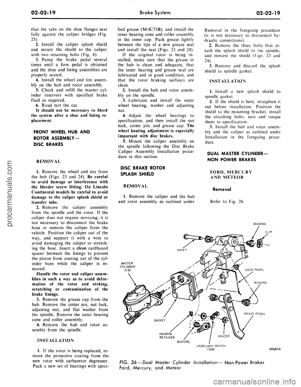
Refer to Fig. 26.
BUSHING
HAIRPIN
RETAINER
BUSHING
STOPLIGHT SWITCH
13480
HI 637-A
FIG. 26—Dual Master Cylinder Installation— Non Power Brakes
Ford,
Mercury, and Meteorprocarmanuals.com
Page 66 of 413
03-01-01
PART
3-1
PAGE
Suspension,
Steering, Wheels and
Tires,
General Service 03-01-01
PART
3-2
Suspension 03-02-01
PART
3-3
Automatic
Air
Leveling System ....03-03-01
PART
3-4
Automatic
Air
Leveling System
Lincoln Continental 03-04-01
PART
3-5
Steering Columns and Linkage ... 03-05-01
PART
3-6
Manual Steering 03-06-01
PART
3-7
Ford Design Non-Integral Power
Steering System
03-07-01
PART
3-8
PAGE
Ford Design Integral Power
Steering Gear 03-08-01
PART
3-9
Saginaw Design Integral Power
Steering Gear 03-09-01
PART
3-10
Ford-Thompson Power Steering
Pump 03-10-01
PART
3-11
Eaton Power Steering Pump 03-1
1-01
PART 3-12
Wheels and Tires 03-1 2-01
PART
3-13
Specifications
03-13-01
PART
3-1
Suspension,Steering, Wheels
and
Tires—General Service
COMPONENT INDEX
CASTER AND CAMBER ADJUSTMENTS
FRONT
END
INSPECTION
FRONT WHEEL ALIGNMENT CHECKS
LUBRICANT CHECKING PROCEDURE
POWER STEERING GEAR CLEANING
AND INSPECTION
POWER STEERING PRELIMINARY TESTS
POWER STEERING PUMP
Cleaning
and
Inspection
Flow
and
Pressure Tests
POWER STEERING SYSTEM FLUSHING
SHOCK ABSORBER CHECKS
STEERING WHEEL SPOKE POSITION
Adjustment
TOE-IN ADJUSTMENT
WHEEL BALANCING
MODEL APPLICATION
All
Models
01-08
01-03
01-07
01-09
01-02
01-11
01-07
01-07
01-07
Ford
01-05
01-09
01-02
01-09
Mercury
01-05
01-09
01-02
01-09
Meteor
01-05
01-09
01-02
01-09
Cougar
01-06
01-09
01-02
01-09
Fairlane
01-06
01-09
01-02
01-09
Falcon
01-06
01-09
01-02
01-09
Montego
01-06
01-09
01-02
Gl-09
Mustang
01-06
01-09
01-02
01-09
Lincoln-
Continental
01-06
01-09
01-03
N/A
Thunderbird
01-05
01-09
01-02
01-09
Continental-
Mark
III
01-05
01-10
01-03
N/A
A page number indicates that
the
item
is for the
vehicle listed
at the
head
of the
column.
N/A indicates that
the
item
is not
applicable
to the
vehicle listed.
procarmanuals.com
Page 69 of 413
03-01-04
Suspension — Steering, Wheels And Tires — General Service
03-01-04
Tool
- T 65 P -
3000
B or C
1266-B
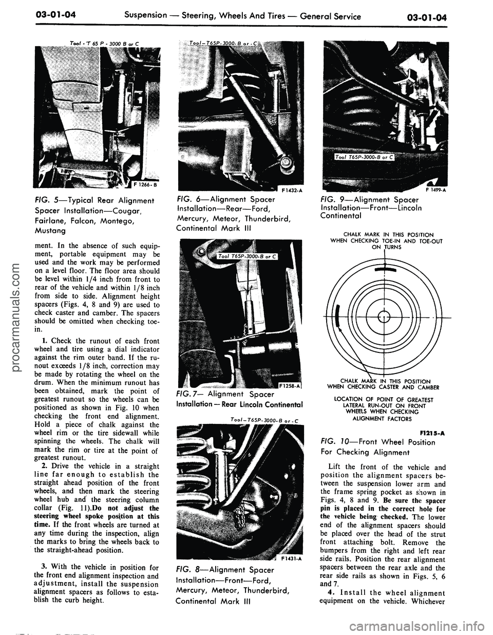
FIG. 5—Typical Rear Alignment
Spacer Installation—Cougar,
Fairlane, Falcon, Montego,
Mustang
ment. In the absence of such equip-
ment, portable equipment may be
used and the work may be performed
on a level floor. The floor area should
be level within 1/4 inch from front to
rear of the vehicle and within 1/8 inch
from side to side. Alignment height
spacers (Figs. 4, 8 and 9) are used to
check caster and camber. The spacers
should be omitted when checking toe-
in.
1.
Check the runout of each front
wheel and tire using a dial indicator
against the rim outer band. If the ru-
nout exceeds 1/8 inch, correction may
be made by rotating the wheel on the
drum. When the minimum runout has
been obtained, mark the point of
greatest runout so the wheels can be
positioned as shown in Fig. 10 when
checking the front end alignment.
Hold a piece of chalk against the
wheel rim or the tire sidewall while
spinning the wheels. The chalk will
mark the rim or tire at the point of
greatest runout.
2.
Drive the vehicle in a straight
line far enough to establish the
straight ahead position of the front
wheels, and then mark the steering
wheel hub and the steering column
collar (Fig. ll).Do not adjust the
steering wheel spoke position at this
time. If the front wheels are turned at
any time during the inspection, align
the marks to bring the wheels back to
the straight-ahead position.
3.
With the vehicle in position for
the front end alignment inspection and
adjustment, install the suspension
alignment spacers as follows to esta-
blish the curb height.
F1432-A
FIG. 6—Alignment Spacer
Installation—Rear—Ford,
Mercury, Meteor, Thunderbird,
Continental Mark III
|F1258-Af
FIG. 7— Alignment Spacer
Installation — Rear Lincoln Continental
Tool-T65P-3000-B or -C
F1431-A
FIG. 8—Alignment Spacer
Installation—Front—Ford,
Mercury, Meteor, Thunderbird,
Continental Mark III
F 1499-A
FIG. 9—Alignment Spacer
Installation—Front—Lincoln
Continental
CHALK MARK IN THIS POSITION
WHEN CHECKING TOE-IN AND TOE-OUT
ON TURNS
CHALK MARK IN THIS POSITION
WHEN CHECKING CASTER AND CAMBER
LOCATION OF POINT OF GREATEST
LATERAL RUN-OUT ON FRONT
WHEaS WHEN CHECKING
ALIGNMENT FACTORS
F1215-A
FIG. 70—Front Wheel Position
For Checking Alignment
Lift the front of the vehicle and
position the alignment spacers be-
tween the suspension lower arm and
the frame spring pocket as shown in
Figs.
4, 8 and 9. Be sure the spacer
pin is placed in the correct hole for
the vehicle being checked. The lower
end of the alignment spacers should
be placed over the head of the strut
front attaching bolt. Remove the
bumpers from the right and left rear
side rails. Position the rear alignment
spacers between the rear axle and the
rear side rails as shown in Figs. 5, 6
and 7.
4.
Install the wheel alignment
equipment on the vehicle. Whicheverprocarmanuals.com
Page 73 of 413
03-01-08
Suspension
—
Steering,
Wheels
And
Tires
—
General Service
03-01-08
3.
Remove the lower (upper on
Mustang and Cougar) cover- to-
housing attaching bolt.
4.
With a clean punch or like in-
strument, clean out or push inward
the loose lubricant in the filler plug
hole and cover to housing attaching
bolt hole.
5.
Slowly turn the steering wheel to
the left stop, lubricant should rise
within the lower cover bolt hole; then
slowly turn the steering wheel to the
right stop, lubricant should rise within
the filler plug hole. If lubricant does
not rise in both the cover bolt hole
and the filler plug hole, add lubricant
until it comes out both holes during
this check.
6. Install the lower (upper on
Mustang and Cougar) cover- to-
housing attaching bolt and the filler
plug.
CLEANING
AND
INSPECTION
FRONT
END
GENERAL
INSPECTION
Do not check and adjust front
wheel alignment without first making
the following inspection for front-end
damage, or wear.
1.
Check for specified air pressures
in all four tires.
2.
Raise the front of the vehicle off
the floor. Shake each front wheel
grasping the upper and lower surfaces
of the tire. Check the front suspension
ball joints and mountings for loose-
ness,
wear, and damage. Check the
brake backing plate mountings. Tor-
que all loose nuts and bolts to specifi-
cation. Replace all worn parts as out-
lined in Part 3-2.
3.
Check the steering gear mount-
ings and all steering linkage connec-
tions for looseness. Torque all mount-
ings to specifications. If any of the
linkage is worn or bent, replace the
parts as outlined in Part 3-5.
4.
Check the front wheel bearings.
If any in-and-out free play is noticed,
adjust the bearings to specifications.
Replace worn or damaged bearings as
outlined in Part 3-12.
5.
Spin each front wheel with a
wheel spinner, and check and balance
each wheel as required.
6. Check the action of the shock
absorbers. If the shock absorbers are
not in good condition, the vehicle may
not settle in a normal, level position,
and front wheel alignment may be af-
fected.
WHEEL INSPECTION
Wheel hub nuts should be inspected
and tightened to specification at pre-
delivery. Loose wheel hub nuts may
cause shimmy and vibration. Elongat-
ed stud holes in the wheels may also
result from loose hub nuts.
Keep the wheels and hubs clean.
Stones wedged between the wheel and
drum and lumps of mud or grease can
unbalance a wheel and tire.
Check for damage that would affect
the runout of the wheels. Wobble or
shimmy caused by a damaged wheel
will eventually damage the wheel bear-
ings.
Inspect the wheel rims for dents
that could permit air to leak from the
tires.
UPPER BALL JOINT
INSPECTION
Ford,
Mercury,
Meteor,
Thunderbird,
Lincoln Continental
and
Continental Mark
III
1.
Raise the vehicle and place floor
jacks beneath the lower arms.
2.
Ask an assistant to grasp the
lower edge of the tire and move the
wheel in and out.
3.
As the wheel is being moved in
and out, observe the upper end of the
spindle and the upper arm.
4.
Any movement between the
upper end of the spindle and the upper
arm indicates ball joint wear and loss
of preload. If any such movement is
observed, replace the upper ball joint.
During
the
foregoing
check,
the
lower ball joint will
be
unloaded
and
may
move.
Disregard
all
such
move-
ment
of the
lower ball
joint.
Also,
do
not mistake loose wheel bearings
for a
worn ball
joint.
Cougar,
Fairlane,
Falcon,
Montego
and
Mustang
1.
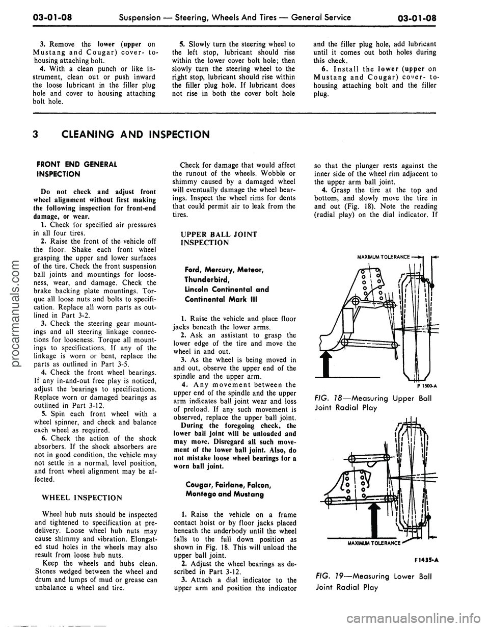
Raise the vehicle on a frame
contact hoist or by floor jacks placed
beneath the underbody until the wheel
falls to the full down position as
shown in Fig. 18. This will unload the
upper ball joint.
2.
Adjust the wheel bearings as de-
scribed in Part 3-12.
3.
Attach a dial indicator to the
upper arm and position the indicator
so that the plunger rests against the
inner side of the wheel rim adjacent to
the upper arm ball joint.
4.
Grasp the tire at the top and
bottom, and slowly move the tire in
and out (Fig. 18). Note the reading
(radial play) on the dial indicator. If
MAXIMUM TOLERANCE
F
1500-A
FIG.
T8—Measuring Upper Ball
Joint Radial Play
MAXIMUM TOLERANCE
F14
35-A
FIG.
79—Measuring Lower Ball
Joint Radial Playprocarmanuals.com
Page 76 of 413
03-01-11
Suspension — Steering, Wheels And Tires — General Service
03-01-11
3.
Inspect the rotor, rollers, cam
ring, pressure plate, cover, and bush-
ing in the pressure plate for wear or
scoring. If damaged, replacement of
the pump (less housing) is required.
4.
Make sure the inner faces of the
cover and the housing are free of
paint, nicks, or burrs. Check all fluid
passages for restrictions.
5.
Inspect the valving surfaces
(areas where the rotor and rollers con-
tact) for wear or scoring. Replace the
pressure plate or the cover if worn or
scored. Inspect the bushing in the
pressure plate for wear or scoring, and
replace the plate if necessary.
6. Inspect the control valve for
scores, nicks, or burred edges. Re-
place the valve if damaged. Do not dis-
assemble the valve. Check the valve
for free movement in the housing
bore.
7.
Inspect the tube seat in the hous-
ing. If damaged, remove it with an
E-Z-Out and install a new seat.
SHOCK ABSORBER CHECKS
All vehicles are equipped with hy-
draulic shock absorbers of the direct-
acting type and are nonadjustable and
nonrefillable. They cannot be repaired.
Before replacing a shock absorber,
check the action of the shock absor-
bers as follows:
ON VEHICLE TESTS
1.
Check the shock absorber to be
sure it is securely and properly in-
stalled. Check the shock absorber in-
sulators for damage and wear.
Replace any defective insulators and
tighten attachments to the specified
torque (on a shock absorber which in-
corporates integral insulators, replace
the shock absorbers).
2.
Inspect the shock absorber for
evidence of fluid leakage. A light film
of fluid is permissible. Be sure any
fluid observed is not from sources
other than the shock absorber.
Replace the shock absorber if leak-
age is severe.
3.
Disconnect the lower end of the
shock absorber. Extend and compress
the shock absorber as fast as possible,
using as much travel as possible.
Action should become smooth and
uniform throughout each stroke.
Higher resistance on extension than
on compression is a normal condition.
Faint swish noises are also normal.
Remove the shock absorber for a
bench test if action is erratic. If the
action is smooth, but the shock absor-
bers are suspected of being weak fol-
low step 4:
4.
Repeat step 3 on the mating
shock absorber installed on the oppo-
site side of the vehicle, and compare
results of both tests. If the action is
similar, it is unlikely that either shock
absorber is defective. Reconnect both
shock absorbers.
Replace the shock absorber having
the lower resistance. Ensure that the
part number of the replacement is the
same as that of the original shock ab-
sorber. The replacement shock absor-
ber resistance will appear to be higher
than either original due to initial fric-
tion of the rod seal.
BENCH TEST
With the shock absorber right side
up (as installed in vehicle), extend it
fully. Then turn the shock absorber
upside down and fully compress it.
Repeat this procedure at least three
times to ensure that any entrapped air
has been expelled. Now place the
shock absorber right side up in a vise,
and hand stroke the shock absorber as
described in On Vehicle Tests, step 3.
If action is not now smooth and uni-
form, install a new shock absorber.procarmanuals.com
Page 77 of 413
03-02-01
Suspension
03-02-01
PART
3-2
Suspension
COMPONENT INDEX
BALL JOINT
Removal
and
Installation
BUSHING
Removal
and
Installation
DRIVE SHAFT PINION ANGLE
Adjustment
FRONT SHOCK ABSORBER
Removal
and
Installation
FRONT SPRING
Removal
and
Installation
FRONT SPRING
AND
LOWER
ARM
Removal
and
Installation
FRONT SUSPENSION
Description
FRONT SUSPENSION LOWER
ARM
Removal
and
Installation
FRONT SUSPENSION LOWER
ARM
STRUT
AND/OR BUSHING
Adjustment
and
Repair
FRONT SUSPENSION UPPER
ARM
Removal
and
Installation
FRONT SUSPENSION UPPER
ARM
BUSHING
- ARM
REMOVED
Disassembly
and
Overhaul
FRONT WHEEL SPINDLE
Removal
and
Installation
HOISTING INSTRUCTIONS
INNER SHAFT
Removal
and
Installation
LOWER
ARM -
REMOVED
Disassembly
and
Overhaul
LOWER
ARM
STRUT AND/OR BUSHING
Removal
and
Installation
LOWER BALL JOINT
- ARM IN
VEHICLE
Removal
and
Installation
REAR SHACKLE
AND
HANGER ASSEMBLY
Removal
and
Installation
REAR SHOCK ABSORBER
Removal
and
Installation
REAR SHOCK ABSORBER LOWER
MOUNTING STUD
Removal ancl Installation
MODEL APPLICATION
All Models
02-02
02-08
Ford
N/A
N/A
02-11
02-21
02-12
N/A
02-16
02-11
02-17
02-27
02-19
N/A
N/A
N/A
02-09
N/A
02-21
N/A
Mercury
N/A
N/A
02-11
02-21
02-12
N/A
02-16
02-11
02-17
02-27
02-19
N/A
N/A
N/A
02-09
N/A
02-21
N/A
Meteor
N/A
N/A
02-11
02-21
02-12
N/A
02-16
02-11
02-17
02-27
02-19
N/A
N/A
N/A
02-09
N/A
02-21
N/A
Cougar
N/A
N/A
N/A
02-21
02-13
N/A
02-17
N/A
02-18
N/A
02-20
N/A
N/A
02-11
N/A
N/A
02-22
N/A
Fairlane
N/A
N/A
N/A
02-21
02-13
N/A
02-17
N/A
02-18
N/A
02-20
N/A
N/A
02-11
N/A
N/A
02-22
N/A
Falcon
N/A
N/A
N/A
02-21
02-13
N/A
02-17
N/A
02-18
N/A
02-20
N/A
N/A
02-11
N/A
N/A
02-22
N/A
Montego
N/A
N/A
N/A
02-21
02-13
N/A
02-17
N/A
02-18
N/A
02-20
N/A
N/A
02-11
N/A
N/A
02-22
N/A
Mustang
N/A
N/A
N/A
02-21
02-13
N/A
02-17
N/A
02-18
N/A
02-20
N/A
N/A
02-11
N/A
N/A
02-22
N/A
Lincoln-
Continental
02-10
02-28
N/A
02-21
N/A
02-14
N/A
N/A
02-18
N/A
02-20
02-28
02-27
N/A
N/A
02-29
02-22
02-23
Thunderbird
N/A
N/A
02-11
02-21
02-12
N/A
02-16
02-11
02-17
02-27
02-19
N/A
N/A
N/A
02-09
N/A
02-21
N/A
1
Continental-
Mark
III
N/A
N/A
02-11
02-21
02-12
N/A
02-16
02-11
02-17
02-27
02-19
N/A
N/A
•
N/A
02-09
N/A
02-21
N/A
A page number indicates that the item
is for the
vehicle listed
at
the head
of
the column.
N/A indicates that
the
item
is not
applicable
to the
vehicle listed.
procarmanuals.com
Page 78 of 413
03-02-02
Suspension
03-02-02
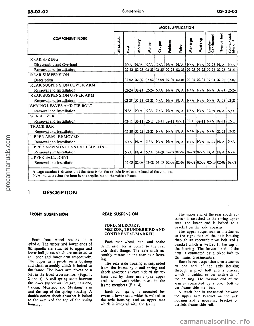
COMPONENT INDEX
REAR SPRING
Disassembly
and
Overhaul
Removal
and
Installation
REAR SUSPENSION
Description
REAR SUSPENSION LOWER
ARM
Removal
and
Installation
REAR SUSPENSION UPPER
ARM
Removal
and
Installation
SPRING LEAVES
AND
TIE-BOLT
Removal
and
Installation
STABILIZER
Removal
and
Installation
TRACK
BAR
Removal
and
Installation
UPPER
ARM
-
REMOVED
Removal
and
Installation
UPPER
ARM
SHAFT AND/OR BUSHING
Removal
and
Installation
UPPER BALL JOINT
Removal
and
Installation
MODEL APPLICATION
All
Models
Ford
N/A
02-23
02-02
02-24
02-25
N/A
02-11
02-25
N/A
N/A
02-08
Mercury
N/A
02-23
02-02
02-24
02-25
N/A
02-11
02-25
N/A
N/A
02-08
Meteor
N/A
02-23
02-02
02-24
02-25
N/A
02-11
02-25
N/A
N/A
02-08
Cougar
N/A
02-25
02-04
N/A
N/A
N/A
02-11
N/A
N/A
02-09
02-08
Fairlane
N/A
02-25
02-04
N/A
N/A
N/A
02-11
N/A
N/A
02-09
02-08
Falcon
N/A
02-25
02-04
N/A
N/A
N/A
02-11
N/A
N/A
02-09
02-08
Montego
N/A
02-25
02-04
N/A
N/A
N/A
02-11
N/A
N/A
02-09
02-08
Mustang
N/A
02-25
02-04
N/A
N/A
N/A
02-11
N/A
N/A
02-09
02-08
Lincoln-
Continental
02-28
02-26
02-04
N/A
N/A
02-29
N/A
N/A
02-27
N/A
02-10
Thunderbird
N/A
02-23
02-02
02-24
02-25
N/A
02-11
02-25
N/A
N/A
02-08
Continental-
Mark III
N/A
02-23
02-02
02-24
02-25
N/A
02-11
02-25
N/A
N/A
02-08
A page number indicates that
the
item
is
for the
vehicle listed
at
the
head
of
the
column.
N/A indicates that
the
item
is
not
applicable
to
the
vehicle listed.
DESCRIPTION
FRONT SUSPENSION
Each front wheel rotates
on a
spindle.
The
upper
and
lower ends
of
the spindle
are
attached
to
upper
and
lower ball joints which
are
mounted
to
an upper
and
lower
arm
respectively.
The upper
arm
pivots
on a
bushing
and shaft assembly which
is
bolted
to
the frame.
The
lower
arm
pivots
on a
bolt
in the
front crossmember (Figs.
1,
2
and 3). A
coil spring seats between
the lower (upper
on
Cougar, Fairlane,
Falcon, Montego
and
Mustang)
arm
and
the top of the
spring housing.
A
double action shock absorber
is
bolted
to
the arm and the top of the
spring
housing.
REAR SUSPENSION
FORD, MERCURY,
METEOR, THUNDERBIRD
AND
CONTINENTAL MARK
III
Each rear wheel,
hub, and
brake
drum assembly
is
bolted
to the
rear
axle shaft flange.
The
axle shaft
as-
sembly rotates
in the
rear axle hous-
ing.
The rear axle housing
is
suspended
from
the
frame
by a
coil spring
and
shock absorber
at
each side
of the ve-
hicle
and by
three arms
(one
upper
and
two
lower) which pivot
in the
frame members
(Fig.
4).
Each coil spring
is
mounted
be-
tween
a
lower seat, which
is
welded
to
the axle housing,
and an
upper seat
which
is
integral with
the
frame.
The upper
end
of
the
rear shock
ab-
sorber
is
attached
to the
spring upper
seat;
the
lower
end is
bolted
to a
bracket
on the
axle housing.
The upper suspension
arm
attaches
to
the
right side
of the
axle housing
through
an
eccentric pivot bolt
and a
bracket which
is
welded
to the top of
the housing.
The
forward
end of the
arm
is
connected
by a
pivot bolt
to
the frame crossmember.
Each lower suspension
arm
attaches
to
one end of the
axle housing
through
a
pivot bolt
and a
bracket
which
is
welded
to the
underside
of
the housing.
The
forward
end of the
arm
is
connected
by a
pivot bolt
to
the frame side member.
A track
bar is
connected between
the upper
arm
bracket
on the
axle
housing
and a
mounting bracket
on
the left frame side rail.
procarmanuals.com
Page 80 of 413
03-02-04
Suspension
03-02-04
COUGAR, FAIRLANE,
FALCON, MONTEGO,
MUSTANG
LINCOLN CONTINENTAL
Each rear wheel, hub and brake
drum assembly is bolted to the rear
axle shaft flange. The wheel and axle
shaft assembly rotates in the rear axle
housing. Two spring pads, integral
with the axle housing, rest on two leaf
spring assemblies. The axle housing is
fastened to the center of the springs
by spring clips (U-bolts), retainers,
and nuts (Figs. 5 and 6). Each spring
assembly is suspended from the under-
body side rail by hanger and shackle
assemblies at the front and rear. The
integral mounting stud at the upper
end of each shock absorber is attached
to the crossmember by a mounting
plate. The lower end is mounted to a
stud which is integral with a bracket
welded to the axle housing.
SHOCK ABSORBER
UPPER MOUNTING
BRACKET
SPRING
SHOCK ABSORBER
UPPER ARM
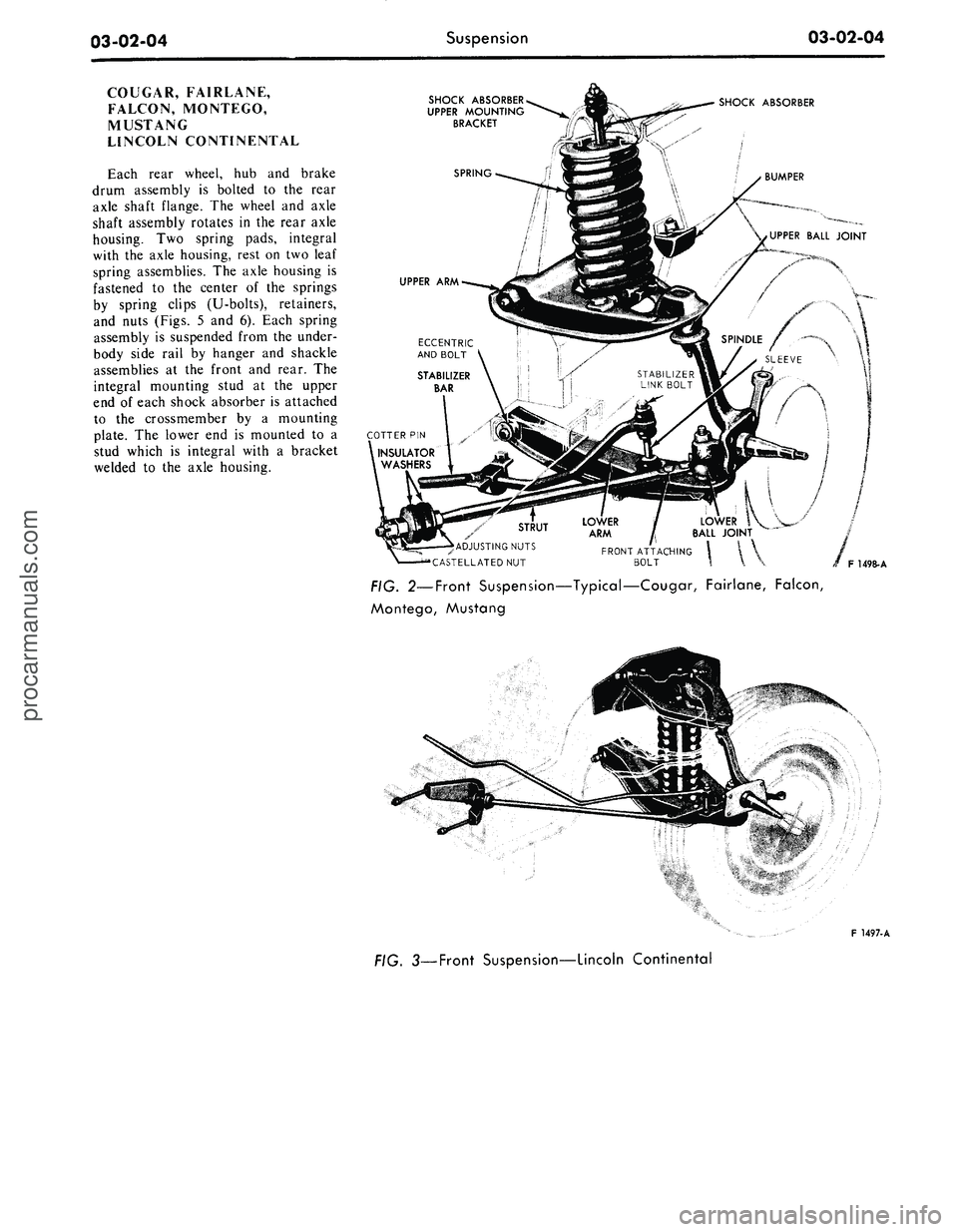
FIG. 2—Front Suspension—Typical—Cougar, Fairlane, Falcon,
Montego, Mustang
F
1497.
A
3—Front Suspension—Lincoln Continentalprocarmanuals.com