clutch FORD MUSTANG 1969 Volume One Chassis
[x] Cancel search | Manufacturer: FORD, Model Year: 1969, Model line: MUSTANG, Model: FORD MUSTANG 1969Pages: 413, PDF Size: 75.81 MB
Page 39 of 413
02-02-20
Brake System
02-02-20
1.
Disconnect the stoplight switch
wires at the connector. Remove the
spring retainer. Slide the stop light
switch off the brake pedal pin just far
enough to clear the end of the pin,
then liftfthe switch straight upward
from the pin. Use care to avoid switch
damage during removal.
2.
Slide the master cylinder push
rod and the nylon washers and bush-
ings off the brake pedal pin.
3.
Remove the brake tube from the
primary and secondary outlet ports of
the master cylinder.
4.
Remove the cap screws and lock-
washers that secure the master cylin-
der to the dirSh panel and lift the cyl-
inder forward and upward from the
vehicle.
Installation
1.
Position the boot on the push
rod and secure the boot to the master
cylinder. Carefully insert the master
cylinder push rod and boot through
the dash panel opening and position
the master cylinder on the panel.
2.
Install the cap screws at the dash
panel and torque them to specifica-
tion.
3.
Coat the nylon bushings with
SAE 10W oil. Install the nylon wash-
er and bushing on the brake pedal pin.
4.
Position the stop light switch on
the brake pedal pin, install the nylon
bushing and washer and secure them
in position with the spring retainer.
5.
Connect the wires at the stop
light switch connector.
6. Connect the brake lines to the
master cylinder leaving the brake line
fittings loose.
7.
Fill the master cylinder with the
specified brake fluid to within 1/4
inch of the top of the dual reservoirs.
Use Ford Brake Fluid— Extra Heavy
Duty-Part Number C6AZ-19542-A
(ESA-M6C25-A) or equivalent for all
drum brake applications. The extra
heavy duty brake system fluid is col-
ored blue for identification. Do not
mix low temperature brake fluids with
the specified fluid for the power disc
brake system.
8. Bleed the dual-master cylinder
and the primary and secondary brake
systems. Centralize the pressure dif-
ferential valve. Refer to Hydraulic
System Bleeding and Centralizing of
the Differential Valve, Part 2-1, Sec-
tion 2 for proper procedure.
9. Operate the brakes several times,
then check for external hydraulic
leaks.
FAIRLANE, MONTEGO,
FALCON, MUSTANG AND
COUGAR
Removal
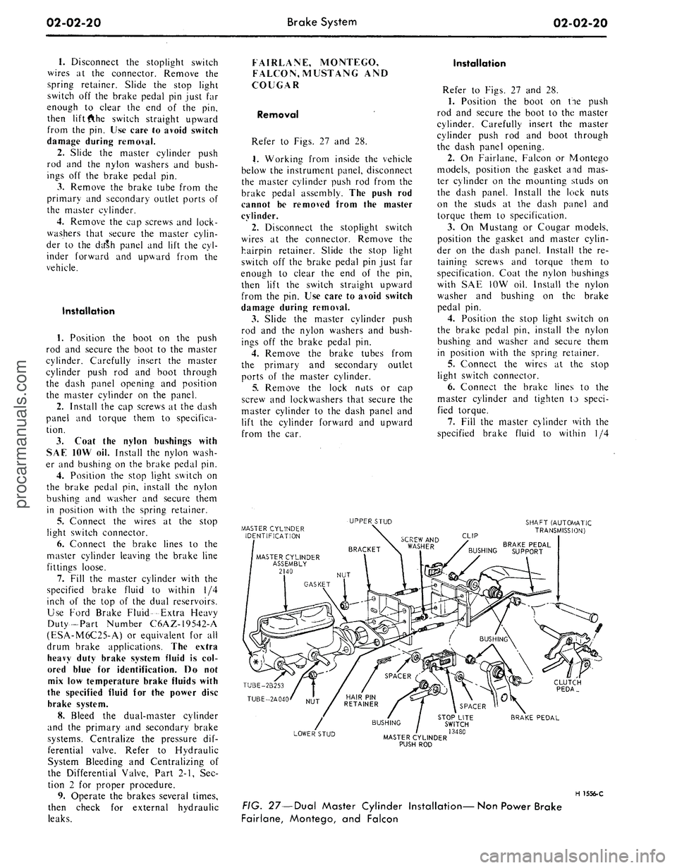
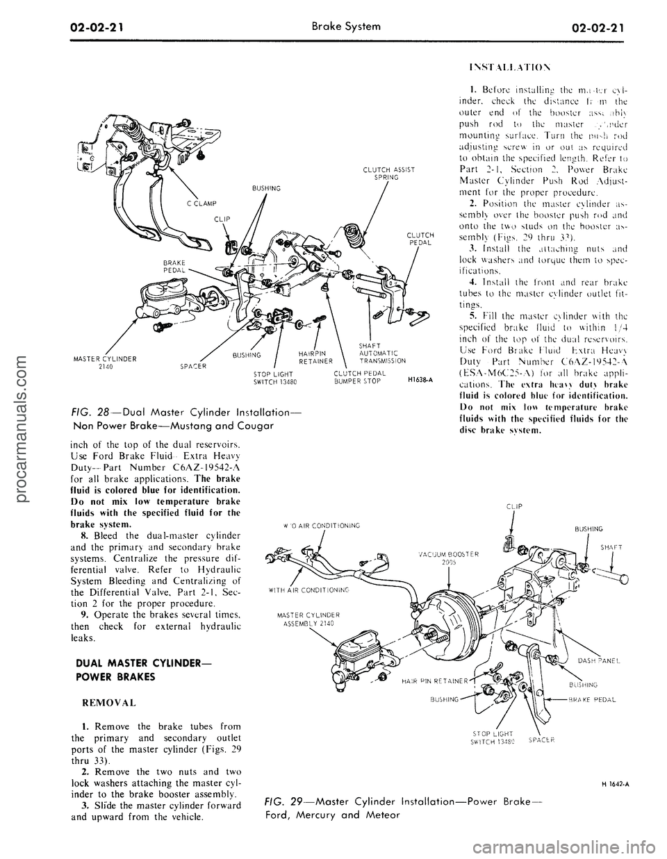
Refer to Figs. 27 and 28.
1.
Working from inside the vehicle
below the instrument panel, disconnect
the master cylinder push rod from the
brake pedal assembly. The push rod
cannot be removed from the master
cylinder.
2.
Disconnect the stoplight switch
wires at the connector. Remove the
hairpin retainer. Slide the stop light
switch off the brake pedal pin just far
enough to clear the end of the pin,
then lift the switch straight upward
from the pin. Use care to avoid switch
damage during removal.
3.
Slide the master cylinder push
rod and the nylon washers and bush-
ings off the brake pedal pin.
4.
Remove the brake tubes from
the primary and secondary outlet
ports of the master cylinder.
5.
Remove the lock nuts or cap
screw and lockwashers that secure the
master cylinder to the dash panel and
lift the cylinder forward and upward
from the car.
Installation
Refer to Figs. 27 and 28.
1.
Position the boot on tie push
rod and secure the boot to the master
cylinder. Carefully insert the master
cylinder push rod and boot through
the dash panel opening.
2.
On Fairlane, Falcon or Montego
models, position the gasket and mas-
ter cylinder on the mounting studs on
the dash panel. Install the lock nuts
on the studs at the dash panel and
torque them to specification.
3.
On Mustang or Cougar models,
position the gasket and master cylin-
der on the dash panel. Install the re-
taining screws and torque them to
specification. Coat the nylon bushings
with SAE 10W oil. Install the nylon
washer and bushing on the brake
pedal pin.
4.
Position the stop light switch on
the brake pedal pin, install the nylon
bushing and washer and secure them
in position with the spring retainer.
5.
Connect the wires at the stop
light switch connector.
6. Connect the brake lines to the
master cylinder and tighten to speci-
fied torque.
7.
Fill the master cylinder with the
specified brake fluid to within 1/4
MASTER CYLINDER
IDENTIFICATION
UPPER STUD
SHAFT (AUTOf/lATIC
TRANSMISSION)
CLIP
BRAKE PEDAL
BUSHING SUPPORT
TUBE-2B253
TUBE-2A040
CLUTCH
PEDA_
LOWER STUD
STOP LITE
SWITCH
/ 13480
MASTER CYLINDER
PUSH ROD
BRAKE PEDAL
H 1556-C
FIG. 27—Dual Master Cylinder Installation—Non Power Brake
Fairlane, Montego, and Falconprocarmanuals.com
Page 40 of 413
02-02-21
Brake System
02-02-21
INSTALLATION
CLUTCH ASSIST
SPRING
MASTER CYLINDER
2140
FIG. 28 —Dual Master Cylinder Installation—
Non Power Brake—Mustang and Cougar
inch of the top of the dual reservoirs.
Use Ford Brake Fluid- Extra Heavy
Duty-Part Number C6AZ-19542-A
for all brake applications. The brake
fluid is colored blue for identification.
Do not mix low temperature brake
fluids with the specified fluid for the
brake system.
8. Bleed the dual-master cylinder
and the primary and secondary brake
systems. Centralize the pressure dif-
ferential valve. Refer to Hydraulic
System Bleeding and Centralizing of
the Differential Valve, Part 2-1, Sec-
tion 2 for the proper procedure.
9. Operate the brakes several times,
then check for external hydraulic
leaks.
DUAL MASTER CYLINDER-
POWER BRAKES
REMOVAL
1.
Remove the brake tubes from
the primary and secondary outlet
ports of the master cylinder (Figs. 29
thru 33).
2.
Remove the two nuts and two
lock washers attaching the master cyl-
inder to the brake booster assembly.
3.
Slide the master cylinder forward
and upward from the vehicle.
SHAFT
AUTOMATIC
TRANSMISSION
CLUTCH PEDAL
BUMPER STOP
H1638-A
1.
Before installing the mater cyl-
inder, check the distance t; m the
outer end of the booster ass;. ,ihi\
push rod to the master .>',nder
mounting surface. Turn the nu->h rod
adjusting screw in or out as required
to obtain the specified length. Refer to
Part 2-1, Section 2. Power Brake
Master Cylinder Push Rod Adjust-
ment for the proper procedure.
2.
Position the master cylinder as-
sembly over the booster push rod and
onto the two studs on the booster as-
sembly (Figs. 29 thru 37).
3.
Install the attaching nuts and
lock washers and torque them to spec-
ifications.
4.
Install the front and rear brake
tubes to the master cylinder outlet fit-
tings.
5.
Fill the master cylinder with the
specified brake fluid to within 1/4
inch of the top o\ the dual reservoirs.
Use Ford Brake Fluid Fxtra Heavy
Duty Part Number C6AZ-19542-A
(ESA-M6C25-A) for all brake appli-
cations. The extra htaw duty brake
fluid is colored blue for identification.
Do not mix low temperature brake
fluids with the specified fluids for the
disc brake svstem.
CLIP
W
'0 AIR CONDITIONING
BUSHING
SHAFT
BUSHING
BRAKE PEDAL
SPACER
H 1642-A
FIG. 29—Master Cylinder Installation-
Ford,
Mercury and Meteor
-Power Brake-procarmanuals.com
Page 41 of 413
02-02-22
Brake System
02-02-22
BRAKE VACUUM BOOSTER -2005
AUTOMATIC I
TRANSMISSION
HAIR PIN RETAINER
330699-S2
SPACER
STOP LIGHT SWITCH-13480
STANDARD
TRANSMISSION
BUSHING
BUSHING
PUSH ROD
BRAKE PEDAL ASSEMBLY
CLUTCH
PEDAL
ASSEMBLY
H 1557-C
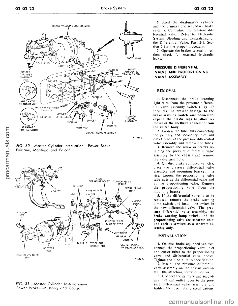
FIG. 30—Master Cylinder Installation—Power Brake-
Fairlane, Montego and Falcon
ASSIST
SPRING BRACKET CLUTCH ASSIST
\ SPRING
BRAKE PEDAL
SHAFT
CLUTCH
PEDAL
CLUTCH PEDAL
TO EQUALIZER ROD
HI643-
A
FIG. 31—Master Cylinder Installation-
Power Brake—Mustang and Cougar
6. Bleed the dual-master cylinder
and the primary and secondary brake
systems. Centralize the pressure dif-
ferential valve. Refer to H>draulic
System Bleeding and Centralizing of
the Differential Valve, Part 2-1, Sec-
tion 2 for the proper procedure.
7.
Operate the brakes several times,
then check for external hydraulic
leaks.
PRESSURE DIFFERENTIAL
VALVE AND PROPORTIONING
VALVE ASSEMBLY
REMOVAL
1.
Disconnect the brake warning
light wire from the pressure differen-
tial valve assembly switch (Figs. 17
thru 21). To prevent damage to the
brake warning switch wire connector,
expand the plastic lugs to allow re-
moval of the shellwire connector from
the switch body.
2.
Loosen the tube nuts connecting
the primary and secondary inlet and
outlet tubes at the pressure differential
valve assembly and remove the tubes.
3.
Remove the screw or screws re-
taining the pressure differential valve
assembly to the chassis and remove
the valve assembly.
4.
On disc brake equipped vehicles,
place the pressure differential valve
assembly and mounting bracket in a
vise.
Loosen the proportioning valve
tube nuts at the differential valve and
at the proportioning valve. Remove
the proportioning valve from the
mounting bracket.
5.
If the differential valve is to be
replaced, remove the brake warning
lamp switch and install the switch in
the new differential valve. The pres-
sure differential valve assembly, the
brake warning lamp switch, and the
proportioning valve are separate units
and each is serviced as a separate as-
sembly only.
INSTALLATION
1.
On disc brake equipped vehicles,
connect the proportioning valve inlet
and outlet tubes to the proportioning
valve and differential valve bodies.
Tighten the tube nuts to specification.
2.
Mount the pressure differential
valve assembly on the chassis and in-
stall the attaching screw or screws.
3.
Connect the primary and second-
ary inlet and outlet tubes to the pres-
sure differential valve assembly and
tighten the tube nuts to specifications.procarmanuals.com
Page 44 of 413
02-02-25
Brake System
02-02-25
clearing the pin. Slide the switch com-
pletely onto the pin, and install the
nylon washer as shown in Figs. 29
thru 33. Be careful not to bend or de-
form the switch. Secure these parts to
the pin with the hairpin retainer. Con-
nect the stop light switch wires to the
connector, and install the wires in the
retaining clip.
BRAKE PEDAL
FORD, MERCURY
AND METEOR
Removal
1.
Disconnect the stop light switch
wires at the connector.
2.
Remove the hairpin retainer.
Slide the stop light switch off the
brake pedal pin just far enough for
the switch outer hole to clear the pin,
and then lift the switch straight up-
ward from the pin. Be careful not to
damage the switch during removal.
Slide the master cylinder or booster
push rod and the nylon washers and
bushing off the brake pedal pin (Figs.
26 and 29).
3.
Remove the hairpin type retainer
and washer from the brake pedal
shaft, then remove the shaft, the brake
pedal and the bushings from the pedal
support bracket.
Installation
1.
Apply a coating of SAE 10 En-
gine oil to the bushings and locate
bushings in their proper places on the
pedal assembly and pedal support
bracket (Figs. 26 and 29).
2.
Position the brake pedal assem-
bly to the support bracket, then install
the pedal shaft through the support
bracket and brake pedal assembly. In-
stall the retainer.
3.
Install the inner nylon washer,
the master cylinder or booster push
rod, and the bushing on the brake
pedal pin. Position the switch so that
it straddles the push rod with the
switch slot on the pedal pin and the
switch outer hole just clearing the pin.
Slide the switch completely onto the
pin, and install the nylon washer as
shown in Figs. 26 and 29. Be careful
not to bend or deform the switch. Se-
cure these parts to the pin with the
hairpin retainer.
4.
Connect the stop light switch
wires to the connector, and install the
wires in the retaining clip.
5.
Check the Brake Pedal Free
Height and Travel Measurements,
Part 2-1, Section 1.
FAIRLANE, MONTEGO AND
FALCON—MANUAL-SHIFT
TRANSMISSION
Removal
1.
Remove the clutch pedal assist
spring.
2.
Disconnect the clutch pedal-
to-equalizer rod at the clutch pedal by
removing the retainer and bushing.
3.
Disconnect the stop light switch
wires at the connector.
4.
Remove the switch retainer, and
slide the stop light switch off the
brake pedal pin just far enough for
the switch outer hole to clear the pin.
Then lower the switch away from the
pin.
5. Slide the master cylinder or
booster push rod and the nylon wash-
ers and bushing off from the brake
pedal pin (Figs. 27 and 30).
6. Remove the self-locking pin and
washer from the clutch and brake
pedal shaft, then remove the clutch
pedal and shaft assembly, the brake
pedal assembly, and the bushings from
the pedal support bracket (Figs. 27
and 30).
Installation
1.
Apply a coating of SAE 10 en-
gine oil to the bushings and locate all
bushings in their proper places on the
clutch and brake pedal assemblies.
2.
Position the brake pedal to the
support bracket, then install the clutch
pedal and shaft assembly through the
support bracket and brake pedal as-
sembly. Install the spring clip (Figs.
27 and 30).
3.
Install the clutch pedal assist
spring.
4.
Connect the clutch pedal-
to-equalizer rod to the clutch pedal
assembly with the bushing and the
spring clip retainer. Apply SAE 10
engine oil to the bushing.
5.
Install the inner nylon washer,
the master cylinder or booster push
rod, and the bushing on the brake
pedal pin. Position the switch so that
it straddles the push rod with the
switch slot on the pedal pin and the
switch outer hole just clearing the pin.
Slide the switch completely onto the
pin, and install the outer nylon washer
as shown in Figs. 27 and 30. Secure
these parts to the pin with the
self-
locking pin.
6. Connect the stop light switch
wires to the connector, and install the
wires to the retaining clip.
7.
Adjust the clutch pedal free play
(Group 5) to specification, if required.
8. Check the Brake Pedal Free
Height and Travel Measurements
(Part 2-1, Section 1).
MUSTANG AND COUGAR—
MANUAL-SHIFT
TRANSMISSION
Removal
1.
Disconnect the battery ground
cable from the battery.
2.
Remove the steering column.
Refer to Part 3-4, Section 2 for pro-
cedure.
3.
On non-power brakes, remove
the two cap screws retaining the mas-
ter cylinder to the dash panel and re-
move the two cap screws retaining the
brake pedal support bracket to the
dash panel. On power brakes remove
the two cap screws retaining the
booster to the dash panel.
4.
Working inside the vehicle, se-
cure the clutch pedal against the
bumper stop with a small C-clamp as
shown in Figs. 28 and 31.
5.
Disconnect the clutch pedal-
to-equalizer rod at the clutch pedal by
removing the retainer and bushing.
6. Disconnect the stop light switch
wires at the connector.
7.
Remove the switch retainer and
slide the stop light switch off the
brake pedal pin just far enough for
the switch outer hole to clear the pin.
Then lower the switch away from the
pin.
Remove the master cylinder or
booster push rod, bushing and nylon
washer from the brake pedal pin.
8. Remove the screw retaining the
pedal support bracket to the top inner
cowl bracket (Figs. 28 and 31).
9. Remove the two sheet metal
screws retaining the pedal support
bracket to the dash panel. On power
brakes remove the nuts from the
brake booster studs.
10.
Remove the two screws retain-
ing the pedal support bracket to the
upper cowl brace and lower the pedal
support bracket away from the steer-
ing column studs.
11.
Remove the pedal support
bracket assembly from the vehicle.
12.
Position the pedal and support
bracket assembly in a vise.
13.
Remove the C-clamp to release
the clutch pedal from its bumper stop
and pivot the pedal away from the
bumper.procarmanuals.com
Page 45 of 413
02-02-26
Brake System
02-02-26
14.
Remove the clutch pedal assist
spring.
15.
On non-power brakes, remove
the retainer clip from the clutch and
brake pedal shaft, then remove the
clutch pedal and shaft assembly, the
brake pedal assembly, and the bush-
ings from the pedal support bracket.
On power brakes, remove the retainer
nut from the brake pedal shaft then
remove the pedal shaft, the brake
pedal assembly and the bushings from
the pedal support bracket.
Installation
1. Apply a coating of SAE 10 en-
gine oil to the bushings and locate all
bushings in their proper places on the
clutch and brake pedal assemblies.
2.
On non-power brakes, position
the brake pedal to the pedal support
bracket, then install the clutch pedal
and shaft assembly through the sup-
port bracket and brake pedal assem-
bly. On power brakes position the
brake pedal to the pedal support
bracket, then install the pedal shaft
and nut.
3.
Install the clutch pedal assist
spring and pivot the clutch pedal
against its bumper stop. Secure the
pedal to the stop with a small C-
clamp as shown in Figs. 28 and 31.
4.
Position the pedal support
bracket assembly to the dash panel,
and to the steering column retainer
studs.
5.
Align the pedal support bracket
holes with the holes in the dash panel
and install the two attaching sheet
metal screws. On power brakes install
the nuts on the brake booster studs.
6. Install the two cap screws at-
taching the pedal support bracket to
the upper cowl bracket.
7. Install the cap screw attaching
the pedal support bracket to the top
inner cowl bracket (Figs. 28 and 31).
8. Install the inner nylon washer,
the master cylinder push rod, and the
bushing on the brake pedal pin. Posi-
tion the stop light switch so that it
straddles the push rod with the switch
slot on the pedal pin and the switch
outer hole just clearing the pin. Slide
the switch completely onto the pin,
and install the outer nylon washer as
shown in Figs. 28 and 31. Secure
these parts to the pin with the
self-
locking retainer.
9. Connect the stop light switch
wires to the connector.
10.
Connect the clutch pedal-
to-equalizer rod to the clutch pedal
assembly with the bushing and the
spring clip retainer. Apply SAE 10
engine oil to the bushing. Remove the
C-clamp from the clutch pedal.
11.
Working from the engine side
of the dash panel, on non-power
brakes, install the two cap screws at-
taching the pedal support bracket to
the dash panel. Then install the two
screws attaching the master cylinder
to the dash panel. On power brakes
install the cap screws retaining the
brake booster to the dash panel.
12.
Install the steering column.
Refer to Part 3-4, Section 2 for pro-
cedure.
13.
Adjust the clutch pedal free
play (Group 5) to specification, if re-
quired.
14.
Check the Brake Pedal Free
Height and Travel Measurements
(Part 2-1, Section 1).
15.
Connect the ground cable to the
battery.
FAIRLANE, MONTEGO,
FALCON, MUSTANG
AND COUGAR-
AUTOMATIC TRANSMISSION
Removal
1. Disconnect the stop light switch
wires at the connector.
2.
Remove the self-locking pin and
slide the stop light switch off the
brake pedal pin just far enough for
the switch outer hole to clear the pin.
Then lower the switch away from the
pin. Slide the master cylinder or
booster push rod and the nylon wash-
ers and bushing off from the brake
pedal pin (Figs. 27, 28, 30 and 31).
3.
On all vehicles except Mustang
and Cougar with power brakes, re-
move the self-locking pin and washer
from the brake pedal shaft, then re-
move the shaft, the brake pedal as-
sembly and the bushings from the
pedal support bracket. On Mustang
and Cougar vehicles with power
brakes, remove the locknut and bolt
from the pedal. Remove the pedal as-
sembly from the support bracket (Fig.
3).
Installation
1. Apply a coating of SAE 10 en-
gine oil to the bushings and locate all
the bushings in their proper places on
the pedal assembly and pedal support
bracket (Figs. 27, 28, 30 and 31).
2.
Position the brake pedal assem-
bly to the support bracket, then install
the pedal shaft or bolt through the
support bracket and brake pedal as-
sembly. Install the retainer or locknut.
3.
Install the inner nylon washer,
the master cylinder or booster push
rod, and the bushing on the brake
pedal pin. Position the switch so that
it straddles the push rod with the
switch slot on the pedal pin, and the
switch outer hole just clearing the pin.
Slide the switch completely onto the
pin, and install the outer nylon washer
as shown in Figs. 27, 28, 30 and 31.
Secure these parts to the pin with the
self-locking pin.
4.
Connect the stop light switch
wires to the connector, and install the
wires in the retaining clip.
Check the Brake Pedal Free Height
and Travel Measurements, Part 2,
Section 1.
THUNDERBIRD
AND
CONTINENTAL MARK
III
Removal
1.
Loosen the booster mounting
nuts.
2.
Disconnect the stop light switch
wires at the connector.
3.
Remove the hairpin retainer.
Slide the stop light switch off from
the brake pedal pin just far enough
for
the
switch outer hole
to
clear
the
pin,
and then lift the switch straight
upward from the pin. Slide the master
cylinder push rod and the nylon wash-
ers and bushing off from the brake
pedal pin (Fig. 32).
4.
Remove the pivot bolt and nut
that holds the pedal to the pedal sup-
port bracket. Remove the brake pedal
assembly from the pedal support
bracket, and remove the bushings.
Installation
1. Apply a coating of SAE 10 en-
gine oil to the bushings and locate all
the bushings in their proper places on
the pedal assembly (Fig. 32).
2.
Install the brake pedal assembly
and bushings to the support bracket,
and then install the pivot bolt through
the support bracket and brake pedal
assembly. Install the pivot bolt nut
and torque to specifications.
3.
Install the inner nylon washer,
the master cylinder push rod, and the
bushing on the brake pedal pin. Posi-
tion the switch so that it straddles the
push rod with the switch slot on the
pedal pin and the switch outer hole
just clearing the pin. Slide the switch
completely onto the pin, install the
outer nylon washer as shown in Fig.
32.
Secure these parts to the pin with
the hairpin retainer.procarmanuals.com
Page 136 of 413
03-06-02
Manual Steering
03-06-02
IN-VEHICLE ADJUSTMENTS AND REPAIRS
STEERING WORM AND
SECTOR
GEAR ADJUSTMENTS
The ball nut assembly and the sec-
tor gear must be adjusted properly to
maintain minimum steering shaft end
play (a factor of preload adjustment)
and minimum backlash between sector
gear and ball nut. There are only two
possible adjustments within the recir-
culating ball-type steering gear, and
these should be made in the following
order to avoid damage or gear failure.
1.
Disconnect the Pitman arm from
the steering Pitman-to-idler arm rod.
2.
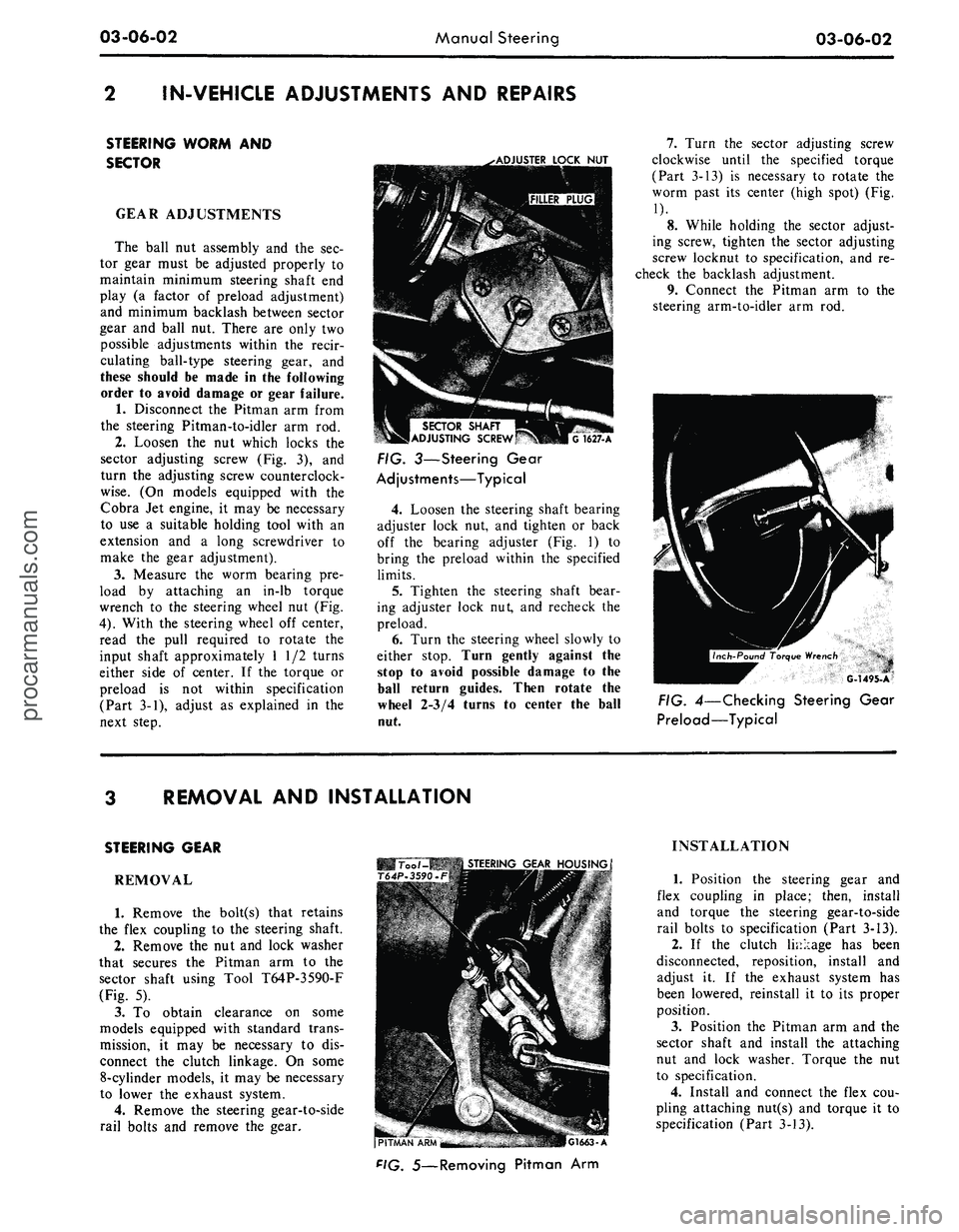
Loosen the nut which locks the
sector adjusting screw (Fig. 3), and
turn the adjusting screw counterclock-
wise.
(On models equipped with the
Cobra Jet engine, it may be necessary
to use a suitable holding tool with an
extension and a long screwdriver to
make the gear adjustment).
3.
Measure the worm bearing pre-
load by attaching an in-lb torque
wrench to the steering wheel nut (Fig.
4).
With the steering wheel off center,
read the pull required to rotate the
input shaft approximately 1 1/2 turns
either side of center. If the torque or
preload is not within specification
(Part 3-1), adjust as explained in the
next step.
.•ADJUSTER
LOCK
NUT
SECTOR
SHAFT
ADJUSTING
SCREW
G
1627-A
FIG. 3—Steering Gear
Adjustments—Typical
4.
Loosen the steering shaft bearing
adjuster lock nut, and tighten or back
off the bearing adjuster (Fig. 1) to
bring the preload within the specified
limits.
5.
Tighten the steering shaft bear-
ing adjuster lock nut, and recheck the
preload.
6. Turn the steering wheel slowly to
either stop. Turn gently against the
stop to avoid possible damage to the
ball return guides. Then rotate the
wheel 2-3/4 turns to center the ball
nut.
7.
Turn the sector adjusting screw
clockwise until the specified torque
(Part 3-13) is necessary to rotate the
worm past its center (high spot) (Fig.
1).
8. While holding the sector adjust-
ing screw, tighten the sector adjusting
screw locknut to specification, and re-
check the backlash adjustment.
9. Connect the Pitman arm to the
steering arm-to-idler arm rod.
G-1495-A
FIG. 4—Checking Steering Gear
Preload—Typical
REMOVAL AND INSTALLATION
STEERING GEAR
REMOVAL
1.
Remove the bolt(s) that retains
the flex coupling to the steering shaft.
2.
Remove the nut and lock washer
that secures the Pitman arm to the
sector shaft using Tool T64P-3590-F
(Fig. 5).
3.
To obtain clearance on some
models equipped with standard trans-
mission, it may be necessary to dis-
connect the clutch linkage. On some
8-cylinder models, it may be necessary
to lower the exhaust system.
4.
Remove the steering gear-to-side
rail bolts and remove the gear.
Too /-MB
STEERING
GEAR
HOUSING
T64P-3590.F
(PITMAN
"APU'^M
-
.-. •
-"
•.:,.17''i.a—
r.iMI.
A
F'G.
5—Removing Pitman Arm
INSTALLATION
1.
Position the steering gear and
flex coupling in place; then, install
and torque the steering gear-to-side
rail bolts to specification (Part 3-13).
2.
If the clutch linkage has been
disconnected, reposition, install and
adjust it. If the exhaust system has
been lowered, reinstall it to its proper
position.
3.
Position the Pitman arm and the
sector shaft and install the attaching
nut and lock washer. Torque the nut
to specification.
4.
Install and connect the flex cou-
pling attaching nut(s) and torque it to
specification (Part 3-13).procarmanuals.com
Page 147 of 413
03-08-03
Ford Design Integral Power Steering Gear
03-08-03
factory adjustments will change. These
changes in adjustment do not neces-
sarily affect the satisfactory operation
of the steering gear assembly, and
therefore ordinarily do not require
readjustment unless there is excessive
lash or other malfunctioning.
ADJUSTMENT IN
VEHICLE
The only adjustment which can be
performed is the total over center
position load, to eliminate excessive
lash between the sector and rack
teeth.
1.
Disconnect the pitman arm from
the sector shaft.
2.
Disconnect the fluid return line
at the reservoir, at the same time cap
the reservoir return line pipe.
3.
Place the end of the return line
in a clean container and cycle the
INPUT SHAFT
SECTOR SHAFT
ADJUSTMENT SCREW
C1547- A
FIG.
2—Adjusting Mesh Load
steering wheel in both directions as re-
quired, to discharge the fluid from the
gear.
4.
Remove the ornamental cover
from the steering wheel hub and turn
the steering wheel to 45 degrees from
the left stop.
5.
Using an in-lb torque wrench on
the steering wheel nut, determine the
torque required to rotate the shaft
slowly through an approximately 1/8
turn from the 45 degree position.
6. Turn the steering gear back to
center, then determine the torque re-
quired to rotate the shaft back and
forth across the center position. Loos-
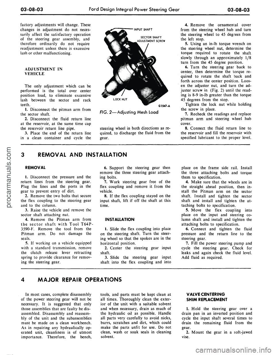
en the adjuster nut, and turn the ad-
juster screw in (Fig. 2) until the read-
ing is 8-9 in-lb greater than the torque
45 degrees from the stop.
Tighten the lock nut while holding
the screw in place.
7.
Recheck the readings and replace
pitman arm and steering wheel hub
cover.
8. Connect the fluid return line to
the reservoir and fill the reservoir with
specified lubricant to the proper level.
REMOVAL AND INSTALLATION
REMOVAL
1.
Disconnect the pressure and the
return lines from the steering gear.
Plug the lines and the ports in the
gear to prevent entry of dirt.
2.
Remove the two bolts that secure
the flex coupling to the steering gear
and to the column.
3.
Raise the vehicle and remove the
sector shaft attaching nut.
4.
Remove the Pitman arm from
the sector shaft with Tool T64P-
3590-F.
Remove the tool from the
Pitman arm. Do not damage the
seals.
5.
If working on a vehicle equipped
with a standard transmission, remove
the clutch release lever retracting
spring to provide clearance for remov-
ing the steering gear.
6. Support the steering gear then
remove the three steering gear attach-
ing bolts.
7.
Work steering gear free of the
flex coupling and remove it from the
vehicle.
8. If the flex coupling stayed on the
input shaft, lift if off the shaft at this
time.
INSTALLATION
1.
Slide the flex coupling into place
on the steering shaft. Turn the steer-
ing wheel so that the spokes are in the
horizontal position.
2.
Center the steering gear input
shaft.
3.
Slide the steering gear input
shaft into the flex coupling and into
place on the frame side rail. Install
the three attaching bolts and torque
them to specification.
4.
Make sure that the wheels are in
the straight ahead position, then in-
stall the Pitman arm on the sector
shaft. Install and tighten the sector
shaft and install and tighten the at-
taching bolts to specification.
5.
Move the flex coupling into
place on the input and steering co-
lumn shaft and install and tighten the
attaching bolts to specification.
6. Connect and tighten the fluid
pressure and the return line to the
steering gear.
7.
Fill the power steering pump and
cycle the steering gear. Check for
leaks and again check the fluid level.
Add fluid as required.
MAJOR REPAIR OPERATIONS
In most cases, complete disassembly
of the power steering gear will not be
necessary. It is suggested that only
those assemblies that are faulty be dis-
assembled. Disassembly and reassem-
bly of the unit and the subassemblies
must be made on a clean workbench.
As in repairing any hydraulically op-
erated unit, cleanliness is of utmost
importance. Therefore, the bench,
tools,
and parts must be kept clean at
all times. Thoroughly clean the exter-
ior of the unit with a suitable solvent
and when necessary, drain as much of
the hydraulic oil as possible. Handle
all parts very carefully to avoid nicks,
burrs,
scratches and dirt, which could
make the parts unfit for use. Do not
clean, wash or soak seals in cleaning
solvent.
VALVE CENTERING
SHIM REPLACEMENT
1.
Hold the steering gear over a
drain pan in an inverted position and
cycle the input shaft several times to
drain the remaining fluid from the
gear.
2.
Mount the gear in a soft-jawed
vise.procarmanuals.com
Page 154 of 413
03-09-02
Saginaw Design Integral Power Steering Gear
03-09-02
WORM
ADJUSTER PLUG
TORSION BAR
STUB SHAFT
SEAL
NEEDLE BEARINGS
TEFLON RING
TEFLON SEALS
SECTOR SHAFT
FIG.l —
Power
Steering Gear—Sectional View
G 1650-A
REMOVAL
AND
INSTALLATION
REMOVAL
1.
Disconnect
the
pressure
and the
return line from
the
steering gear.
Plug
the
lines
and the
ports
in the
gear to prevent entry of dirt.
2.
Remove the two bolts that secure
the flex coupling
to the
steering gear
and
to
the column.
3.
Raise
the
vehicle
and
remove
the
Pitman arm attaching nut.
4.
Remove
the
Pitman arni from
the sector shaft with Tool T64P-3590-
F.
Remove
the
tool from
the
Pitman
arm.
5.
If
working
on a
vehicle equipped
with
a
standard transmission, remove
the clutch release lever retracting spring
to provide clearance
for
removing
the
steering gear.
6. Support
the
steering gear then
remove
the
three steering gear attach-
ing bolts.
7.
Work
the
steering gear free
of
the flex coupling
and
remove
it
from
the vehicle.
8.
If
the flex coupling stayed
on the
input shaft, lift
it off the
shaft
at
this time.
INSTALLATION
1.
Slide
the
flex coupling into place
on
the
steering shaft. Turn
the
steer-
ing wheel
so
that
the
spokes
are in
the horizontal position.
2.
Center
the
steering gear input
shaft.
3.
Slide the steering gear input shaft
into
the
flex coupling
and
into place
on
the
frame side rail. Install the three
attaching bolts
and
torque them
to
specification.
4.
Make sure that
ihe
wheels
are
in
the
straight-ahead position, then
install
the
Pitman
arm on the
sector
shaft. Install
and
tighten
the
sector
shaft attaching nut to specification.
5.
Move the flex coupling into place
on
the
input shaft
and
steering columnprocarmanuals.com
Page 197 of 413
04-01-10
General Axle Service
04-01-10
The pattern taken during disassem-
bly should be helpful in judging if
gears can be re-used. Worn gears can-
not be rebuilt to correct a noisy condi-
tion. Gear scoring is the result of ex-
cessive shock loading or the use of an
incorrect lubricant. Scored gears can-
not be re-used.
Examine the teeth and thrust surfa-
ces of the differential gears. Wear on
the hub of the differential gear can
cause a chucking noise known as
chuckle when the vehicle is driven at
low speeds. Wear of splines, thrust
surfaces, or thrust washers, can con-
tribute to excessive drive line back-
lash.
BEARING CUPS AND
CONE AND ROLLER
ASSEMBLIES
Check bearing cups for rings,
scores, galling, or excessively worn
wear patterns. Pinion cups must be
solidly seated. Check by attempting to
insert a 0.0015-inch feeler between
these cups and the bottoms of their
bores.
When operated in the cups, cone
and roller assemblies must turn with-
out roughness. Examine the roller
ends for wear. Step-wear on the roller
ends indicates the bearings were not
preloaded properly, or the rollers were
slightly misaligned.
If inspection reveals either a defec-
tive cup or a defective cone and roller
assembly, both parts should be re-
placed to avoid early failure.
DIFFERENTIAL BEARING
ADJUSTING NUTS
Temporarily install the bearing caps
and test the fit of the adjusting nuts in
their threads. The nuts should turn
easily when the caps are tightened to
25 ft-lbs. The faces of the nuts that
contact the bearing cups must be
smooth and square. Replace the nuts
or examine the threads in the carrier
if their fit is not proper. Be sure that
the bearing caps and adjusting nuts
are on the side they were machined to
fit. Observe the punch marks and
scribe marks made during disassem-
bly.
U-JOINT FLANGE
Be sure that the eai» of the flange
have not been damaged in removing
the drive shaft or in removing the
flange from the axle. The end of the
flange that contacts the front pinion
bearing inner race as well as the flat
surface of the pinion nut counterbore
must be smooth. Polish these surfaces
if necessary. Roughness aggravates
backlash noises and causes wear of
the flange and pinion nut with a resul-
tant loss in pinion bearing preload.
PINION RETAINER
Be sure that the pinion bearing cups
are seated. Remove any chips or burrs
from the mounting flange. Clean the
groove for the O-ring seal and all lu-
bricant passages. If the cups were re-
moved, examine the bores carefully.
Any nicks or burrs in these bores
must be removed to permit proper
seating of the cups.
CARRIER HOUSING
Make sure that the differential
bearing bores are smooth and the
threads are not damaged. Remove any
nicks or burrs from the mounting sur-
faces of the carrier housing.
DIFFERENTIAL CASE
Make sure that the hubs where the
bearings mount are smooth. Carefully
examine the differential case bearing
shoulders, which may have been dam-
aged when the bearings were removed.
The bearing assemblies will fail if they
do not seat firmly against the shoul-
ders.
Check the fit (free rotation) of
the differential side gears in their
counterbores. Be sure that the mating
surfaces of the two parts of the case
are smooth and free from nicks or
burrs.
LIMITED SLIP AND
TRACTION-LOK
DIFFERENTIAL PARTS
Inspect the clutch plates for uneven
or extreme wear. The dog-eared clutch
plates must be free from burrs, nicks
or scratches which could cause excess-
ive or erratic wear to the bonding ma-
terial of the internally splined clutch
plates.
The internally splined clutch
plates should be inspected for condi-
tion of the bond, bonding material,
and wear. Replace the bonded plates
if their thickness is less than 0.085
inch or if the bonded material is
scored or badly worn. Inspect the
bonded plate internal teeth for wear.
Replace them, if excessive wear is evi-
dent. Bonded plates should be re-
placed as a set only
Examine all thrust surfaces and
hubs for wear. Abnormal wear on
these surfaces can contribute to a
noisy axle.
Inspect the Belleville spring (limited
slip) for proper free height of 1/4
inch.
LUBRICANT LEVEL
The lubricant level should be
checked every 6000 miles with the ve-
hicle in normal curb attitude. The lu-
bricant level should be at the lower
edge of the filler plug hole located in
either the carrier casting or housing
cover. It is unnecessary to periodically
drain the axle lubricant. The factory
fill should remain in the housing for
the life of the vehicle, except when re-
pairs are made. The specified lubri-
cant should be installed when the axle
is overhauled.procarmanuals.com
Page 200 of 413
04-02-03
Rear Axle — Removable Carrier Type
04-02-03
is,
it is supported by bearings both in
front of and to the rear of the pinion
gear. Two opposed tapered roller
bearings support the pinion shaft in
front of the pinion gear with a col-
lapsible spacer for 8-3/4 inch or 9
inch ring gear, and a solid spacer used
with the 9 3/8 inch ring gear. A
straight roller (pilot) bearing supports
the pinion shaft at the rear of the pi-
nion gear. Pinion and ring gear tooth
contact is adjusted by adding or re-
moving shims from between the pinion
retainer and the carrier housing.
The differential assembly is mount-
ed on two opposed tapered roller
bearings, which are retained in the
carrier by removable caps. The entire
carrier assembly is bolted to the axle
housing.
Ball bearing assemblies (rear wheel
bearings) are pressed onto the outer
ends of the axle shafts and set in the
outer ends of the axle housing. These
bearings support the semi-floating
axle shafts at the outer ends. The
inner ends of the shafts spline to the
differential side gears. Bearing retain-
er plates hold the shafts in the hous-
ing. The left and right axle shafts are
not interchangeable, the left shaft
being shorter than the right.
CASE
COVER
BELLEVILLE
SPRING
CLUTC
HUB
STEEL
PLATES
BONDED
PLATES
E1741-A
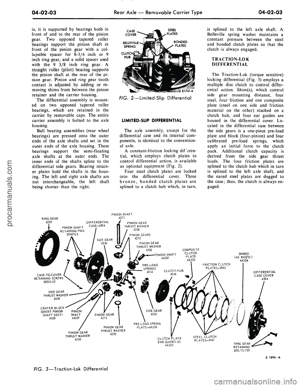
FIG. 2—Limited-Slip Differential
LIMITED-SUP DIFFERENTIAL
The axle assembly, except for the
differential case and its internal com-
ponents, is identical to the convention-
al axle.
A constant-friction locking differen-
tial,
which employs clutch plates to
control differential action, is available
as optional equipment (Fig. 2).
Four steel clutch plates are locked
into the differential cover. Three
bronze, bonded clutch plates are
splined to a clutch hub which, in turn,
is splined to the left axle shaft. A
Belleville spring washer maintains a
constant pressure between the steel
and bonded clutch plates so that the
clutch is always engaged.
TRACTION-LOK
DIFFERENTIAL
The Traction-Lok (torque sensitive)
locking differential (Fig. 3) employs a
multiple disc clutch to control differ-
ential action. Shim(s), which control
side gear mounting distance, four
steel, four friction and one composite
plate (steel on one side and friction
material on the other) stacked on a
clutch hub, and four ear guides are
housed in the differential cover. Lo-
cated in the differential case between
the side gears is a one-piece pre-load
plate and block (four-pinion) and four
calibrated pre-load springs, which
apply an initial force to the clutch
pack. Additional clutch capacity is
derived from the side gear thrust
loads.
The four friction plates are
splined to the clutch hub which in turn
is splined to the left axle shaft, and
the eared steel plates are dogged to
the case; thus, the clutch is always en-
gaged.
PINION SHAFT
4211
PINION SHAFT
RETAINING PINS
359475-S
DIFFERENTIAL
CASE-4204
CASE-TO-COVER
RETAINING SCREWS
50025-S2
SIDE GEAR
THRUST WASHER
4228
CENTER BLOCK
(SHORT PINION PINION
SHAFT SEAT) SHAFT
4420 44207
7
PINION GEAR
THRUST WASHER
4230
PINION GEARS
4215
PINION GEAR
THRUST WASHER
4230
PINION SHAFT
44207
SHIM(S)
(AS REQ'D.)
4A324
DIFFERENTIAL
CASE COVER
4204
PINION GEAR
THRUST WASHER
4230
PRE-LOAD SPRING
PINION GEAR PLATE-4A326
THRUST WASHER
4230
CLUTCH PLATE
EAR GUIDES
(4)
4A323
E 1896-A
FIG. 3—Traction-Lok Differentialprocarmanuals.com