FORD TRANSIT 2006 7.G Body And Equipment Mounting Section Manual
Manufacturer: FORD, Model Year: 2006, Model line: TRANSIT, Model: FORD TRANSIT 2006 7.GPages: 234, PDF Size: 33.19 MB
Page 171 of 234
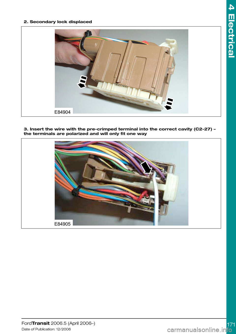
2. Secondary lock displaced
3. Insert the wire with the pre-crimped terminal into the correct cavity (C2-27) –
the terminals are polarized and will only fit one way
FordTransit 2006.5 (April 2006–)
Date of Publication: 12/2006
4 Electrical
171E84904 E84905
Page 172 of 234
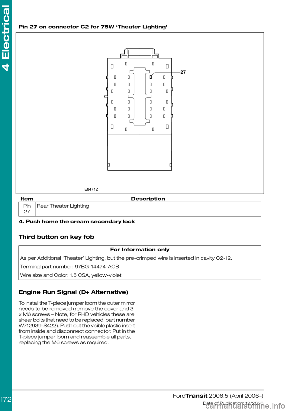
Pin 27 on connector C2 for 75W ‘Theater Lighting’
DescriptionItem
Rear Theater LightingPin
27
4. Push home the cream secondary lock
Third button on key fob
For Information only
As per Additional ‘Theater’ Lighting, but the pre-crimped wire is inserted in cavity C2-12.
Terminal part number: 97BG-14474-ACB
Wire size and Color: 1.5 CSA, yellow-violet
Engine Run Signal (D+ Alternative)
To install the T-piece jumper loom the outer mirror
needs to be removed (remove the cover and 3
x M6 screws – Note, for RHD vehicles these are
shear bolts that need to be replaced, part number
W712939-S422). Push out the visible plastic insert
from inside and disconnect connector. Put in the
T-piece jumper loom and reassemble all parts,
replacing the M6 screws as required.
FordTransit 2006.5 (April 2006–)
Date of Publication: 12/2006
4 Electrical
172E8471227
Page 173 of 234
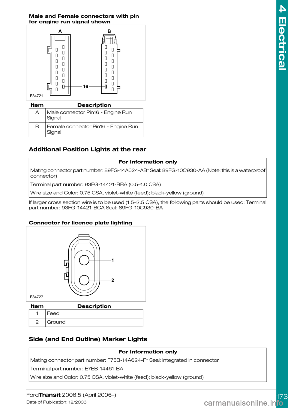
Male and Female connectors with pin
for engine run signal shown
DescriptionItem
Male connector Pin16 - Engine Run
Signal
A
Female connector Pin16 - Engine Run
Signal
B
Additional Position Lights at the rear
For Information only
Mating connector part number: 89FG-14A624-AB* Seal: 89FG-10C930-AA (Note: this is a waterproof
connector)
Terminal part number: 93FG-14421-BBA (0.5–1.0 CSA)
Wire size and Color: 0.75 CSA, violet-white (feed); black-yellow (ground)
If larger cross section wire is to be used (1.5–2.5 CSA), the following parts should be used: Terminal
part number: 93FG-14421-BCA Seal: 89FG-10C930-BA
Connector for licence plate lighting
DescriptionItem
Feed1
Ground2
Side (and End Outline) Marker Lights
For Information only
Mating connector part number: F75B-14A624-F* Seal: integrated in connector
Terminal part number: E7EB-14461-BA
Wire size and Color: 0.75 CSA, violet-white (feed); black-yellow (ground)
FordTransit 2006.5 (April 2006–)
Date of Publication: 12/2006
4 Electrical
173E8472116AB 1E847272
Page 174 of 234
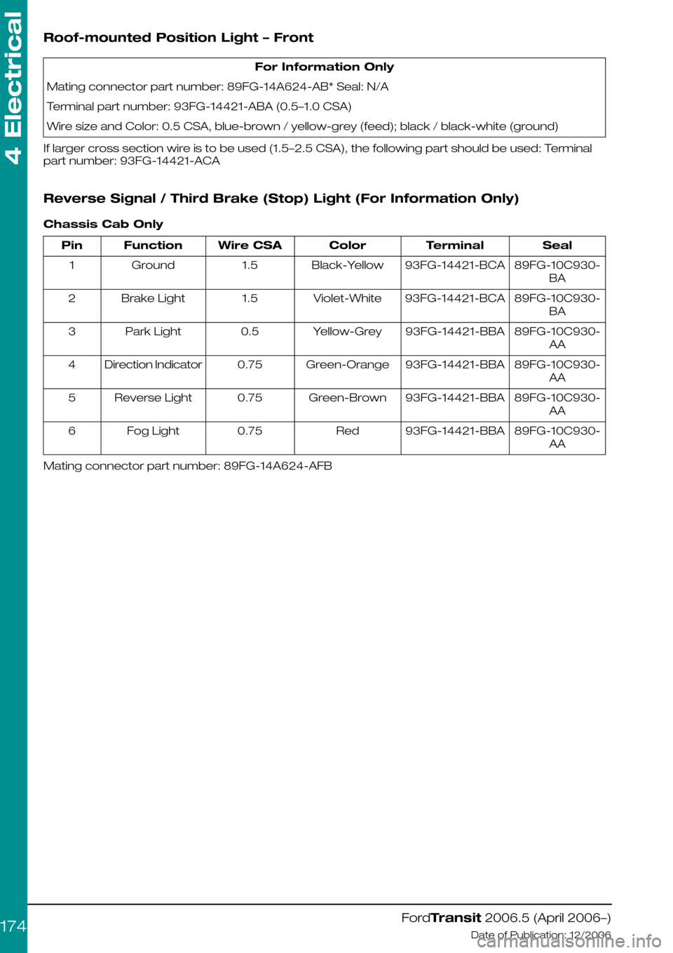
Roof-mounted Position Light – Front
For Information Only
Mating connector part number: 89FG-14A624-AB* Seal: N/A
Terminal part number: 93FG-14421-ABA (0.5–1.0 CSA)
Wire size and Color: 0.5 CSA, blue-brown / yellow-grey (feed); black / black-white (ground)
If larger cross section wire is to be used (1.5–2.5 CSA), the following part should be used: Terminal
part number: 93FG-14421-ACA
Reverse Signal / Third Brake (Stop) Light (For Information Only)
Chassis Cab Only
SealTerminalColorWire CSAFunctionPin
89FG-10C930-
BA
93FG-14421-BCABlack-Yellow1.5Ground1
89FG-10C930-
BA
93FG-14421-BCAViolet-White1.5Brake Light2
89FG-10C930-
AA
93FG-14421-BBAYellow-Grey0.5Park Light3
89FG-10C930-
AA
93FG-14421-BBAGreen-Orange0.75Direction Indicator4
89FG-10C930-
AA
93FG-14421-BBAGreen-Brown0.75Reverse Light5
89FG-10C930-
AA
93FG-14421-BBARed0.75Fog Light6
Mating connector part number: 89FG-14A624-AFB
FordTransit 2006.5 (April 2006–)
Date of Publication: 12/2006
4 Electrical
174
Page 175 of 234
5.1 Body
5.1.1 Body Structures - General
Information
When carrying out vehicle
conversions/modifications the following points
should be considered:
•Make sure that the vehicle structural integrity
is maintained
•Do not drill into closed frame body members.
•Make sure that the design for the body
alterations or additional structure disperse the
load evenly.
CAUTION: Uneven load distribution
could result in unacceptable
handling and braking
characteristics.
•Re-paint metal edges after cutting or drilling.
All metal edges must comply with exterior and
interior protection legislation.
•All fixings through the floor, sides or roof must
be sealed.
Refer to: 5.10 Corrosion Prevention (page 221).
WARNING: Before drilling the floor,
check the no drill zones.
See figure E74574 - Floor (No Drill Zones) under
the Floor Fuel Tank.
•Make sure that fixings in the 'B'-pillar area do
not encroach on the seat belts or seat belt
reels.
For unique floor fixings, see (Frame Drilling and
Tube Reinforcing).
Refer to: 5.11 Frame and Body Mounting (page
222).
For Load Compartment Tie Downs(Load Lashing
Points).
Refer to: 5.2 (page 200).
FordTransit 2006.5 (April 2006–)
Date of Publication: 12/2006
5 Body and Paint
175
Page 176 of 234
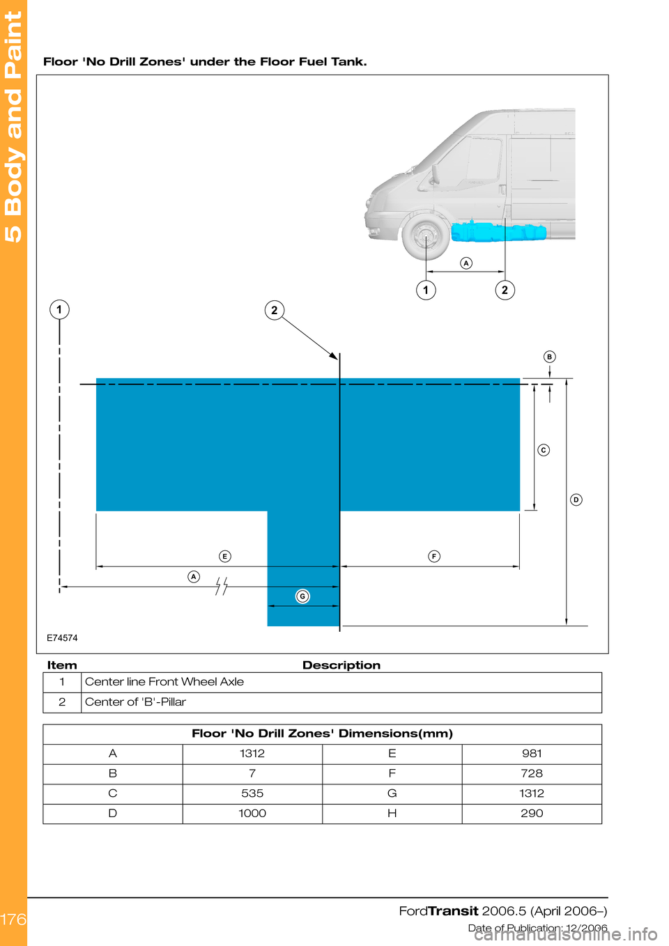
Floor 'No Drill Zones' under the Floor Fuel Tank.
DescriptionItem
Center line Front Wheel Axle1
Center of 'B'-Pillar2
Floor 'No Drill Zones' Dimensions(mm)
981E1312A
728F7B
1312G535C
290H1000D
FordTransit 2006.5 (April 2006–)
Date of Publication: 12/2006
5 Body and Paint
176E745742211ABCDEAFG
Page 177 of 234
5.1.2 Back Panel Removal
When planning and specifying the base vehicle
and the conversion, select the Special Vehicle
Option, which has a detachable cab back panel.
Please consult your local National Sales
Representative for availability.
5.1.3 Integrated Bodies and
Conversions
For integral structures such as ambulances or
motor-homes with increased rear overhang built
onto the chassis the following applies:
•Reduced departure angles, e.g. rear entry
step, should be discussed with the end user
/ customer. Consider removable components
to avoid damage on ferries or low-loaders.
•Unique spare wheel stowage may be required
if obscured by rear step, check for
accessibility.
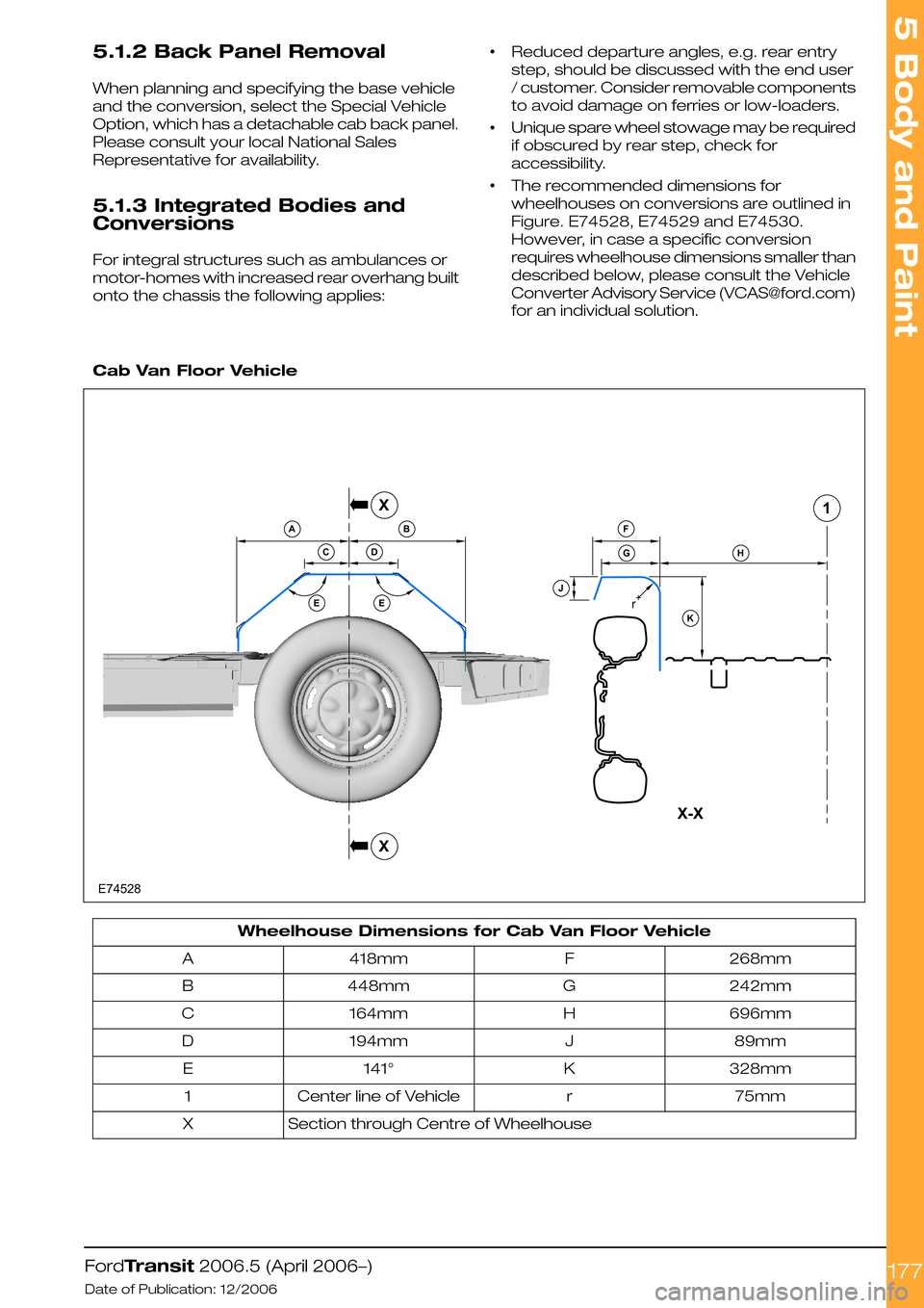
•The recommended dimensions for
wheelhouses on conversions are outlined in
Figure. E74528, E74529 and E74530.
However, in case a specific conversion
requires wheelhouse dimensions smaller than
described below, please consult the Vehicle
Converter Advisory Service ([email protected])
for an individual solution.
Cab Van Floor Vehicle
Wheelhouse Dimensions for Cab Van Floor Vehicle
268mmF418mmA
242mmG448mmB
696mmH164mmC
89mmJ194mmD
328mmK141°E
75mmrCenter line of Vehicle1
Section through Centre of WheelhouseX
FordTransit 2006.5 (April 2006–)
Date of Publication: 12/2006
5 Body and Paint
177E74528rBFGHJKACDEEX1XX-X
Page 178 of 234
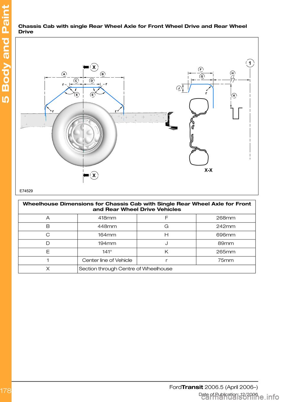
Chassis Cab with single Rear Wheel Axle for Front Wheel Drive and Rear Wheel
Drive
Wheelhouse Dimensions for Chassis Cab with Single Rear Wheel Axle for Front
and Rear Wheel Drive Vehicles
268mmF418mmA
242mmG448mmB
696mmH164mmC
89mmJ194mmD
265mmK141°E
75mmrCenter line of Vehicle1
Section through Centre of WheelhouseX
FordTransit 2006.5 (April 2006–)
Date of Publication: 12/2006
5 Body and Paint
178E74529rrrrrACDBEEFKJHGX1XX-X
Page 179 of 234
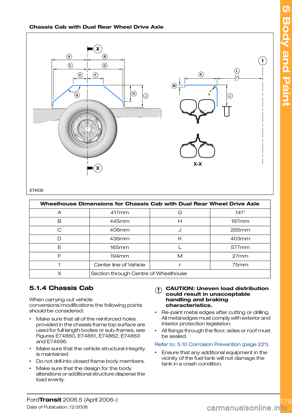
Chassis Cab with Dual Rear Wheel Drive Axle
Wheelhouse Dimensions for Chassis Cab with Dual Rear Wheel Drive Axle
141°G417mmA
197mmH445mmB
265mmJ406mmC
403mmK436mmD
577mmL165mmE
27mmM194mmF
75mmrCenter line of Vehicle1
Section through Centre of WheelhouseX
5.1.4 Chassis Cab
When carrying out vehicle
conversions/modifications the following points
should be considered:
•Make sure that all of the reinforced holes
provided in the chassis frame top surface are
used for full length bodies or sub-frames, see
Figures E74860, E74861, E74862, E74863
and E74696.
•Make sure that the vehicle structural integrity
is maintained
•Do not drill into closed frame body members.
•Make sure that the design for the body
alterations or additional structure disperse the
load evenly.
CAUTION: Uneven load distribution
could result in unacceptable
handling and braking
characteristics.
•Re-paint metal edges after cutting or drilling.
All metal edges must comply with exterior and
interior protection legislation.
•All fixings through the floor, sides or roof must
be sealed.
Refer to: 5.10 Corrosion Prevention (page 221).
•Ensure that any additional equipment in the
vicinity of the fuel tank will not damage the
tank in a crash condition.
FordTransit 2006.5 (April 2006–)
Date of Publication: 12/2006
5 Body and Paint
179rE74530GABDCEFHJMKLJX1XX-X
Page 180 of 234
WARNING: Excessive heat can build
up from the exhaust system, in
particular from the catalytic
converter. Ensure adequate heat
shields are maintained.
NOTE: The reinforcement plate in cab back
panel to chassis member area must be
maintained, please refer to Figure E74543.
Please refer also to the following Illustrations:
•Refer to: 5.11 Frame and Body Mounting (page
222).
(Figure E74576 - Self Supporting Body
Structure, Figure E74517 - Frame Drilling and
Tube Reinforcing and Figure E74577 - Low
floor Standard Chassis Frame).
•Refer to: 5.7 Roof Opening Panel (page 214).
(Figure E74678 - Driver's Standing Head
Room).
For any conversion structure attached to or
mounted onto the base vehicle cab structure the
following applies:
•Ensure that neither the conversion structure
nor the existing vehicle structure get
pre-loaded by the assembly process.
•Adhesive jointing is recommended but should
be supplemented with mechanical fasteners
to prevent initial peel and long term failure.
•Spread bolt loads to minimize local stress.
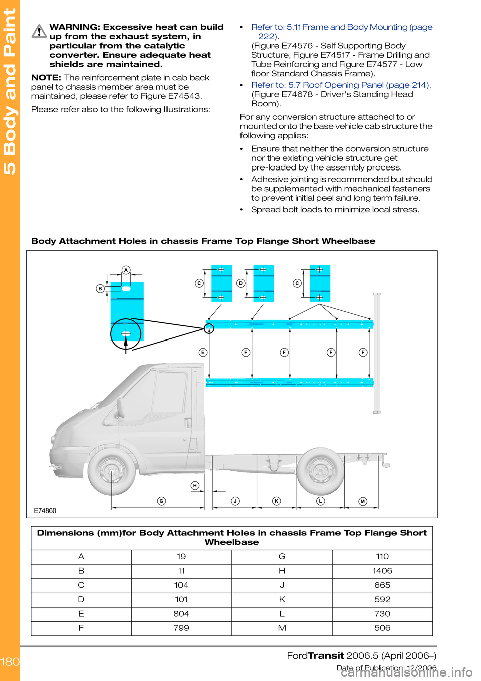
Body Attachment Holes in chassis Frame Top Flange Short Wheelbase
Dimensions (mm)for Body Attachment Holes in chassis Frame Top Flange Short
Wheelbase
110G19A
1406H11B
665J104C
592K101D
730L804E
506M799F
FordTransit 2006.5 (April 2006–)
Date of Publication: 12/2006
5 Body and Paint
180ADBE74860CEFFHGJKLMFFC