FORD TRANSIT 2006 7.G Body And Equipment Mounting Section Manual
Manufacturer: FORD, Model Year: 2006, Model line: TRANSIT, Model: FORD TRANSIT 2006 7.GPages: 234, PDF Size: 33.19 MB
Page 191 of 234
•Sub-frame ends must be relieved at forward
end to minimize local contact stress
concentrations, see Figure E74575.
Refer to: 5.11 Frame and Body Mounting (page
222).
(However it is recommended to mount the
longitudinal onto the mounting brackets with
a clearance to the chassis frame top surface).
•Stiff sub-frames, for example closed section
Longitudinal rigidly connected with similar
section cross members, may damage the
chassis frame by preventing its natural flexing.
Therefore compliant mounts should be used
with up to plus and minus (+/-) 12mm
compliance, vehicle laden or un-laden
which-ever is worst case, rated at 2.0mm
deflection minimum per 200kg mass at each
chassis frame forward mount, please refer to
Figure E74696 for example of compliant
mount and Figure E75880 for location.
•Each set of brackets must use two (2) x M10
bolts grade 8.8 minimum
•For safety device on outriggers/legs please
refer to Van, Kombi and Bus
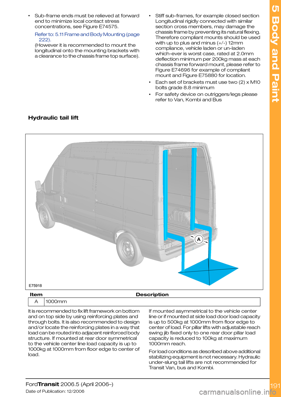
Hydraulic tail lift
DescriptionItem
1000mmA
It is recommended to fix lift framework on bottom
and on top side by using reinforcing plates and
through bolts. It is also recommended to design
and/or locate the reinforcing plates in a way that
load can be routed into adjacent reinforced body
structure. If mounted at rear door symmetrical
to the vehicle center line load capacity is up to
1000kg at 1000mm from floor edge to center of
load.
If mounted asymmetrical to the vehicle center
line or if mounted at side load door load capacity
is up to 500kg at 1000mm from floor edge to
center of load. For pillar lifts with adjustable reach
swing jib fixed only to one rear door pillar load
capacity is reduced to 100kg at maximum
1000mm reach.
For load conditions as described above additional
stabilizing equipment is not necessary. Hydraulic
under-slung tail lifts are not recommended for
Transit Van, bus and Kombi.
FordTransit 2006.5 (April 2006–)
Date of Publication: 12/2006
5 Body and Paint
191E75918A
Page 192 of 234
For Chassis Cab with tail lift design as described
above it is recommended to use unique body
sub-frame for fixing to Chassis Cab structure. For
connection between sub-frame Chassis Cab
body structure please refer to Figure E74696.
For Chassis Cab with under-slung tail lift load
capacity is up to 1000kg at 1000mm from rear
end of chassis frame to center of load if mounted
and functioning on centre line of vehicle. If
mounted and functioning off center line or at the
side of the vehicle load capacity is reduced to
500kg at 1000mm from side/rear end to center
of load.
Greater off-sets and/or loads require additional
stabilizing equipment such as outriggers or
ground jacks. It is recommended not to increase
vehicle body stress over limit as given by load
factors above. If uncertain please consult your
local national sales representative or the Vehicle
Converter Advisory Service [email protected].
It is the Vehicle converters responsibility to fit a
decal to the converted vehicle stating that the
equipment must not be used without
outriggers/ground jacks in operating position. It
is also the vehicle converters responsibility to
guarantee safe functioning of the equipment.
For hydraulic tail lifts as used for general loading
or more specialized for wheel-chair lifts please
refer to Figure E75874.
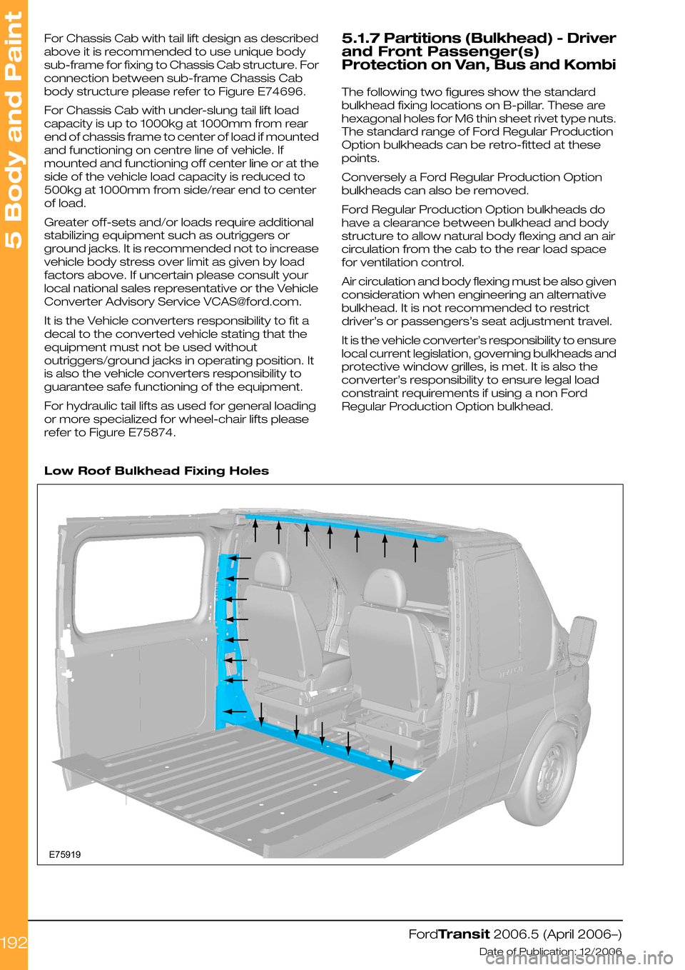
5.1.7 Partitions (Bulkhead) - Driver
and Front Passenger(s)
Protection on Van, Bus and Kombi
The following two figures show the standard
bulkhead fixing locations on B-pillar. These are
hexagonal holes for M6 thin sheet rivet type nuts.
The standard range of Ford Regular Production
Option bulkheads can be retro-fitted at these
points.
Conversely a Ford Regular Production Option
bulkheads can also be removed.
Ford Regular Production Option bulkheads do
have a clearance between bulkhead and body
structure to allow natural body flexing and an air
circulation from the cab to the rear load space
for ventilation control.
Air circulation and body flexing must be also given
consideration when engineering an alternative
bulkhead. It is not recommended to restrict
driver’s or passengers’s seat adjustment travel.
It is the vehicle converter’s responsibility to ensure
local current legislation, governing bulkheads and
protective window grilles, is met. It is also the
converter’s responsibility to ensure legal load
constraint requirements if using a non Ford
Regular Production Option bulkhead.
Low Roof Bulkhead Fixing Holes
FordTransit 2006.5 (April 2006–)
Date of Publication: 12/2006
5 Body and Paint
192E75919
Page 193 of 234
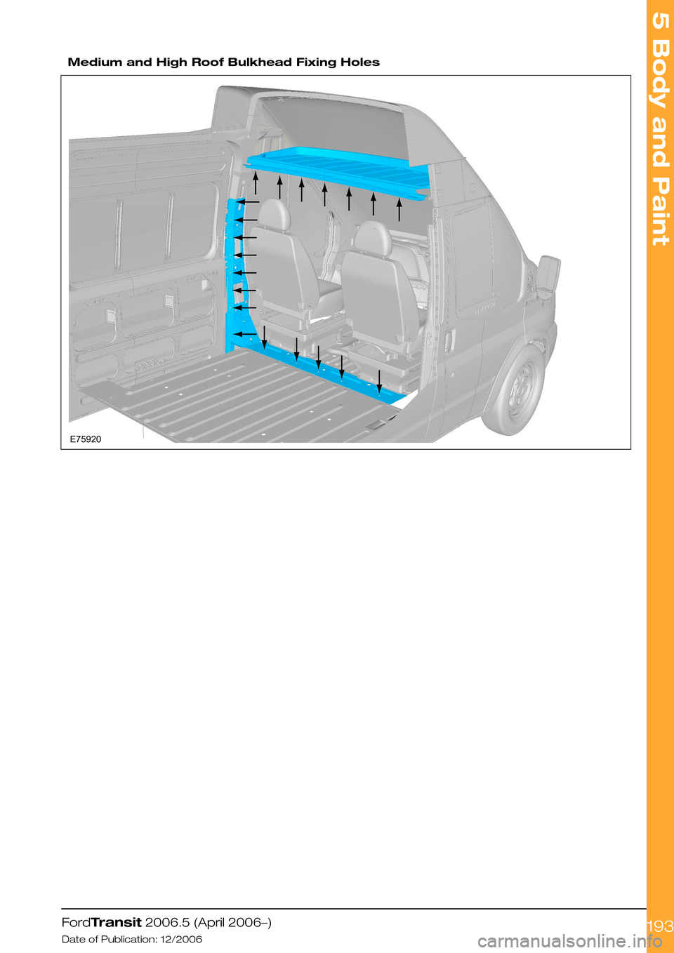
Medium and High Roof Bulkhead Fixing Holes
FordTransit 2006.5 (April 2006–)
Date of Publication: 12/2006
5 Body and Paint
193E75920
Page 194 of 234
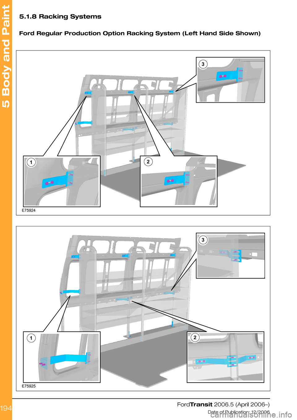
5.1.8 Racking Systems
Ford Regular Production Option Racking System (Left Hand Side Shown)
FordTransit 2006.5 (April 2006–)
Date of Publication: 12/2006
5 Body and Paint
194312E75924 312E75925
Page 195 of 234
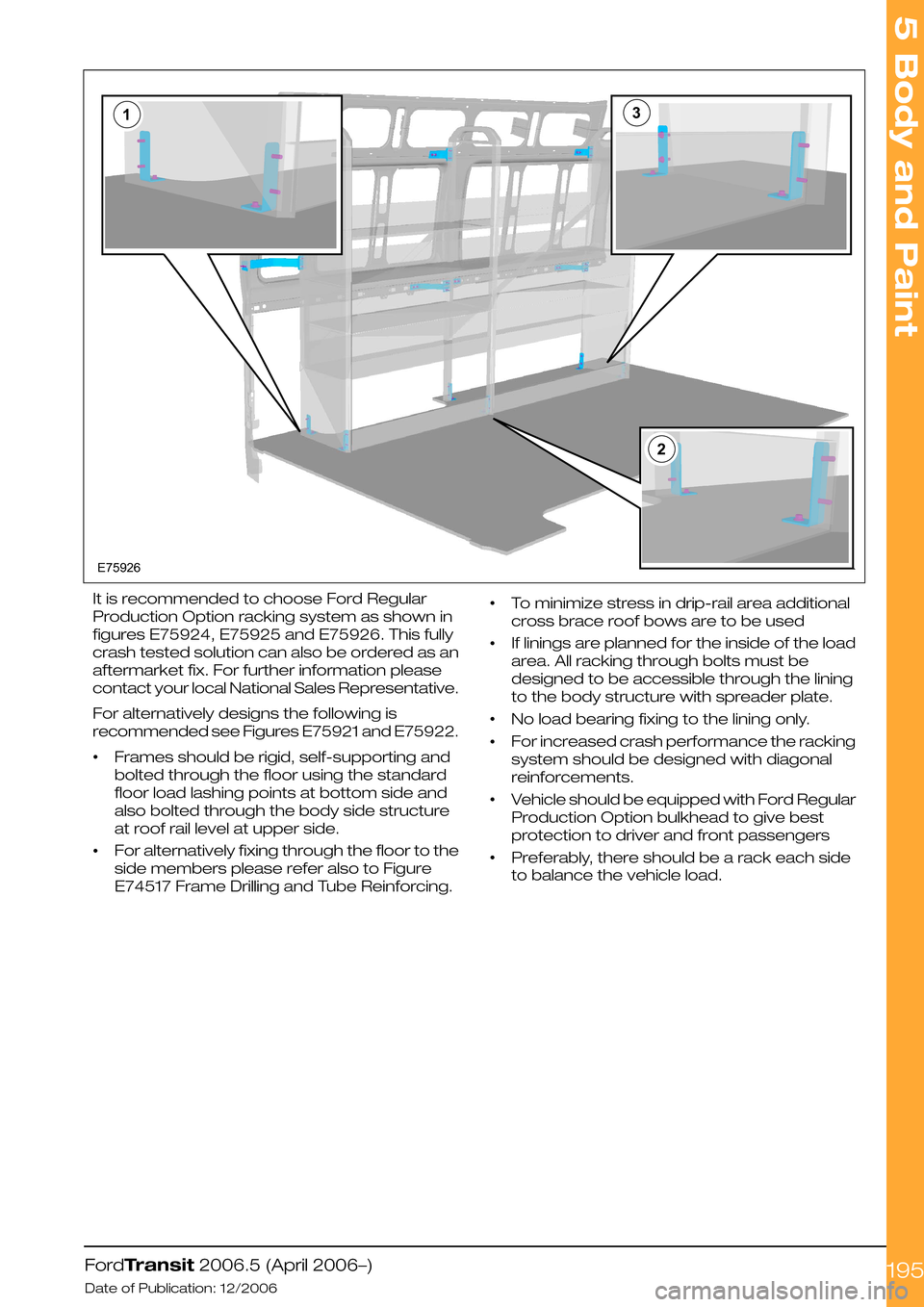
It is recommended to choose Ford Regular
Production Option racking system as shown in
figures E75924, E75925 and E75926. This fully
crash tested solution can also be ordered as an
aftermarket fix. For further information please
contact your local National Sales Representative.
For alternatively designs the following is
recommended see Figures E75921 and E75922.
•Frames should be rigid, self-supporting and
bolted through the floor using the standard
floor load lashing points at bottom side and
also bolted through the body side structure
at roof rail level at upper side.
•For alternatively fixing through the floor to the
side members please refer also to Figure
E74517 Frame Drilling and Tube Reinforcing.
•To minimize stress in drip-rail area additional
cross brace roof bows are to be used
•If linings are planned for the inside of the load
area. All racking through bolts must be
designed to be accessible through the lining
to the body structure with spreader plate.
•No load bearing fixing to the lining only.
•For increased crash performance the racking
system should be designed with diagonal
reinforcements.
•Vehicle should be equipped with Ford Regular
Production Option bulkhead to give best
protection to driver and front passengers
•Preferably, there should be a rack each side
to balance the vehicle load.
FordTransit 2006.5 (April 2006–)
Date of Publication: 12/2006
5 Body and Paint
195213E75926
Page 196 of 234
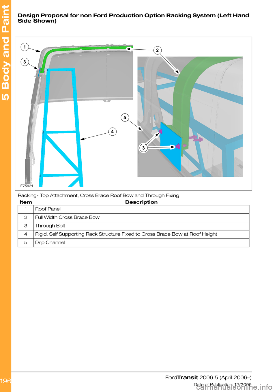
Design Proposal for non Ford Production Option Racking System (Left Hand
Side Shown)
Racking- Top Attachment, Cross Brace Roof Bow and Through Fixing
DescriptionItem
Roof Panel1
Full Width Cross Brace Bow2
Through Bolt3
Rigid, Self Supporting Rack Structure Fixed to Cross Brace Bow at Roof Height4
Drip Channel5
FordTransit 2006.5 (April 2006–)
Date of Publication: 12/2006
5 Body and Paint
196E75921213435
Page 197 of 234
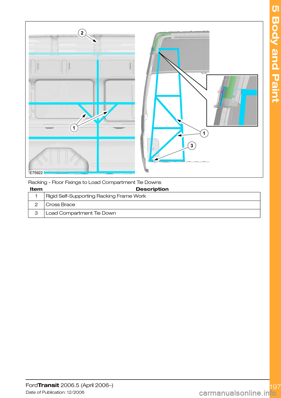
Racking - Floor Fixings to Load Compartment Tie Downs
DescriptionItem
Rigid Self-Supporting Racking Frame Work1
Cross Brace2
Load Compartment Tie Down3
FordTransit 2006.5 (April 2006–)
Date of Publication: 12/2006
5 Body and Paint
1971132E75922
Page 198 of 234
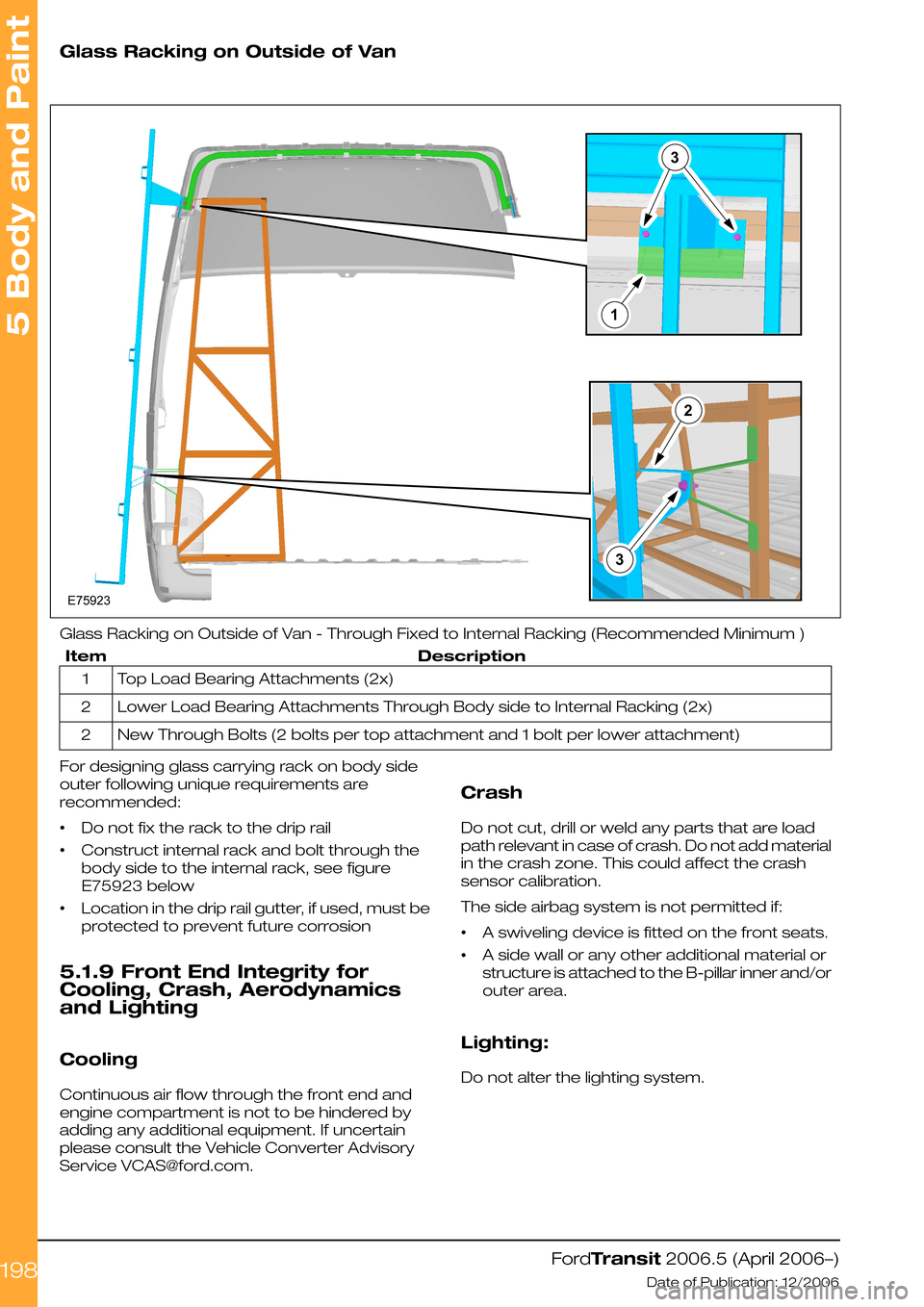
Glass Racking on Outside of Van
Glass Racking on Outside of Van - Through Fixed to Internal Racking (Recommended Minimum )
DescriptionItem
Top Load Bearing Attachments (2x)1
Lower Load Bearing Attachments Through Body side to Internal Racking (2x)2
New Through Bolts (2 bolts per top attachment and 1 bolt per lower attachment)2
For designing glass carrying rack on body side
outer following unique requirements are
recommended:
•Do not fix the rack to the drip rail
•Construct internal rack and bolt through the
body side to the internal rack, see figure
E75923 below
•Location in the drip rail gutter, if used, must be
protected to prevent future corrosion
5.1.9 Front End Integrity for
Cooling, Crash, Aerodynamics
and Lighting
Cooling
Continuous air flow through the front end and
engine compartment is not to be hindered by
adding any additional equipment. If uncertain
please consult the Vehicle Converter Advisory
Service [email protected].
Crash
Do not cut, drill or weld any parts that are load
path relevant in case of crash. Do not add material
in the crash zone. This could affect the crash
sensor calibration.
The side airbag system is not permitted if:
•A swiveling device is fitted on the front seats.
•A side wall or any other additional material or
structure is attached to the B-pillar inner and/or
outer area.
Lighting:
Do not alter the lighting system.
FordTransit 2006.5 (April 2006–)
Date of Publication: 12/2006
5 Body and Paint
198E759233123
Page 199 of 234
Static & Dynamic Sealing and
Finishing
Use Ford approved sealing and finishing material,
and underbody corrosion protection.
Refer to: 5.10 Corrosion Prevention (page 221).
Ensure proper sealing against ingress of water,
salt, dust etc. after cutting or drilling the body.
5.1.10 Tipper Bodies
For tipper conversions single an double Chassis
Cab versions except extended rear chassis
frame can be used. All variants allow single and
three way tipping.
It is recommended to have the tipping system
operative only when the engine is running. It is
also recommended to have the master control
switch in the security of the cab. According
routing of wires and hydraulic lines please refer
to section hydraulic lift.
Ensure that axle plated weights including the
front axle minimum are not exceeded.
For tipper sub-frames please refer to the
following guidelines:
•Design for full length continuous frame with
mountings for motor, pump unit, reservoir,
pivot points and ram
•Use all mounting points on chassis frame to
mount sub-frame
•The rear two sets of chassis frame mounting
brackets should have a full torque with 100%
grip. The attachment to the remaining forward
chassis frame brackets must be precisely
located and retained, but allow some relative
flexing between the sub-frame and chassis
frame. That is clamp control devices such as
conical washer stacks or machine springs with
self locking fastenings.
•Very stiff sub-frames may damage the chassis
frame by preventing its natural flexing,
therefore compliant mounts should be captive
fail safe with up to plus and minus 12mm
compliance, vehicle laden or un-laden
whichever is worst case, rated 2mm
deflection minimum per 200kg mass at each
chassis frame forward mount, please see also
Figures E74696 Sub-frame attachment to
Chassis frame and Figure E75880 Rigid or
Torsion Stiff sub-frame for Chassis Cab.
•Use two M10 grade 8.8 minimum bolts,
washers and self locking nuts at each solid
and compliant chassis frame location.
•Sub-frame must extend to the back of the
cab and attach to all mounting locations, with
the forward end designed to minimize local
frame stress, please refer to Figure E74575
Sub-frame for low floor or other equipment.
However it is preferable to mount the
sub-frame onto the mounting brackets with
a clearance to the chassis frame top surface.
•Side tipping loads/forces must be resolved
by the sub-frame. It is not recommended to
strain the chassis frame.
5.1.11 Tank and Dry Bulk Carriers
Due to the high rigidity of tanks it is necessary to
isolate the tank and its sub-frame from the
chassis frame allowing the chassis frame to
naturally flex. Please refer to the following
guidelines:
•Mount tank to full length of sub-frame.
•Mount sub-frame to all chassis frame
mounting points.
•The rear two sets of chassis frame mounting
brackets should have solid full bolts torque
with 100% grip.
•The remaining forward location mounts must
be compliant to allow relative chassis frame
to sub-frame deflections.
•Sub-frame must extend to the back of the
cab and not contact chassis frame at forward
end under worst case deflection.
•Compliant mounts should have captive fail
safe through bolts, please refer to Figures
E74696 Sub-frame attachment to Chassis
frame and Figure E75880 Rigid or Torsion Stiff
sub-frame for Chassis Cab, with up to
plus/minus 12mm compliance, vehicle laden
or un-laden whatever is worst case, rated at
2.0mm minimum deflection per 200kg mass
each.
•Use two M10 grade 8.8 minimum bolts,
washers and self lock nuts per chassis frame
mount bracket at each solid and compliant
location.
FordTransit 2006.5 (April 2006–)
Date of Publication: 12/2006
5 Body and Paint
199
Page 200 of 234
5.2 Body System - General Information—Specifications
5.2.1 Van Floor - Load Compartment Tie Downs for Van ,Bus and
Kombi
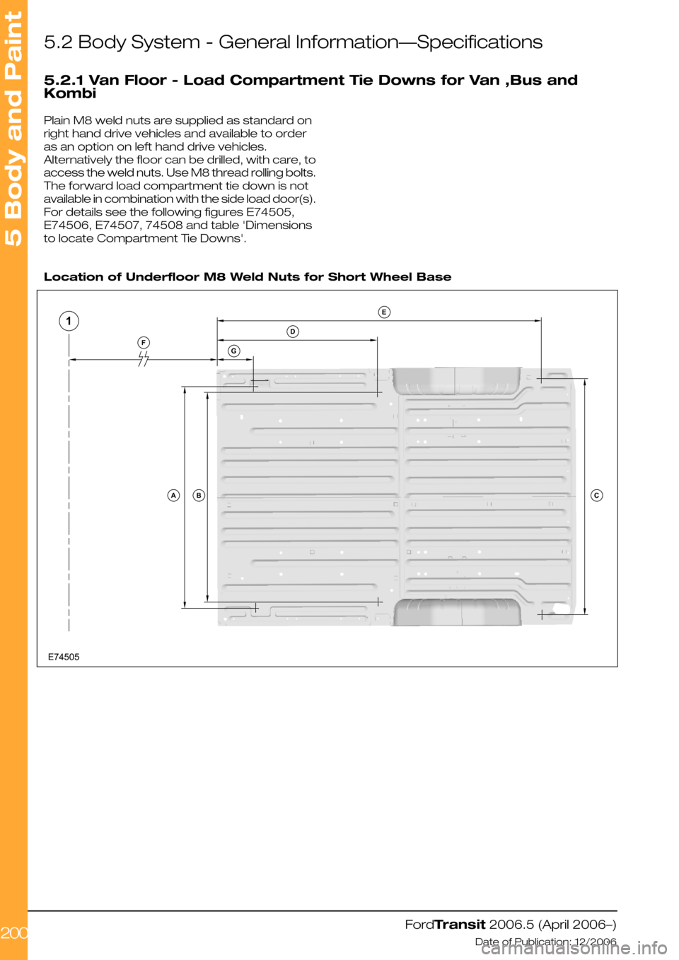
Plain M8 weld nuts are supplied as standard on
right hand drive vehicles and available to order
as an option on left hand drive vehicles.
Alternatively the floor can be drilled, with care, to
access the weld nuts. Use M8 thread rolling bolts.
The forward load compartment tie down is not
available in combination with the side load door(s).
For details see the following figures E74505,
E74506, E74507, 74508 and table 'Dimensions
to locate Compartment Tie Downs'.
Location of Underfloor M8 Weld Nuts for Short Wheel Base
FordTransit 2006.5 (April 2006–)
Date of Publication: 12/2006
5 Body and Paint
200FBCAGDE1E74505