GEELY FC 2008 Owner's Manual
Manufacturer: GEELY, Model Year: 2008, Model line: FC, Model: GEELY FC 2008Pages: 419, PDF Size: 13.87 MB
Page 21 of 419
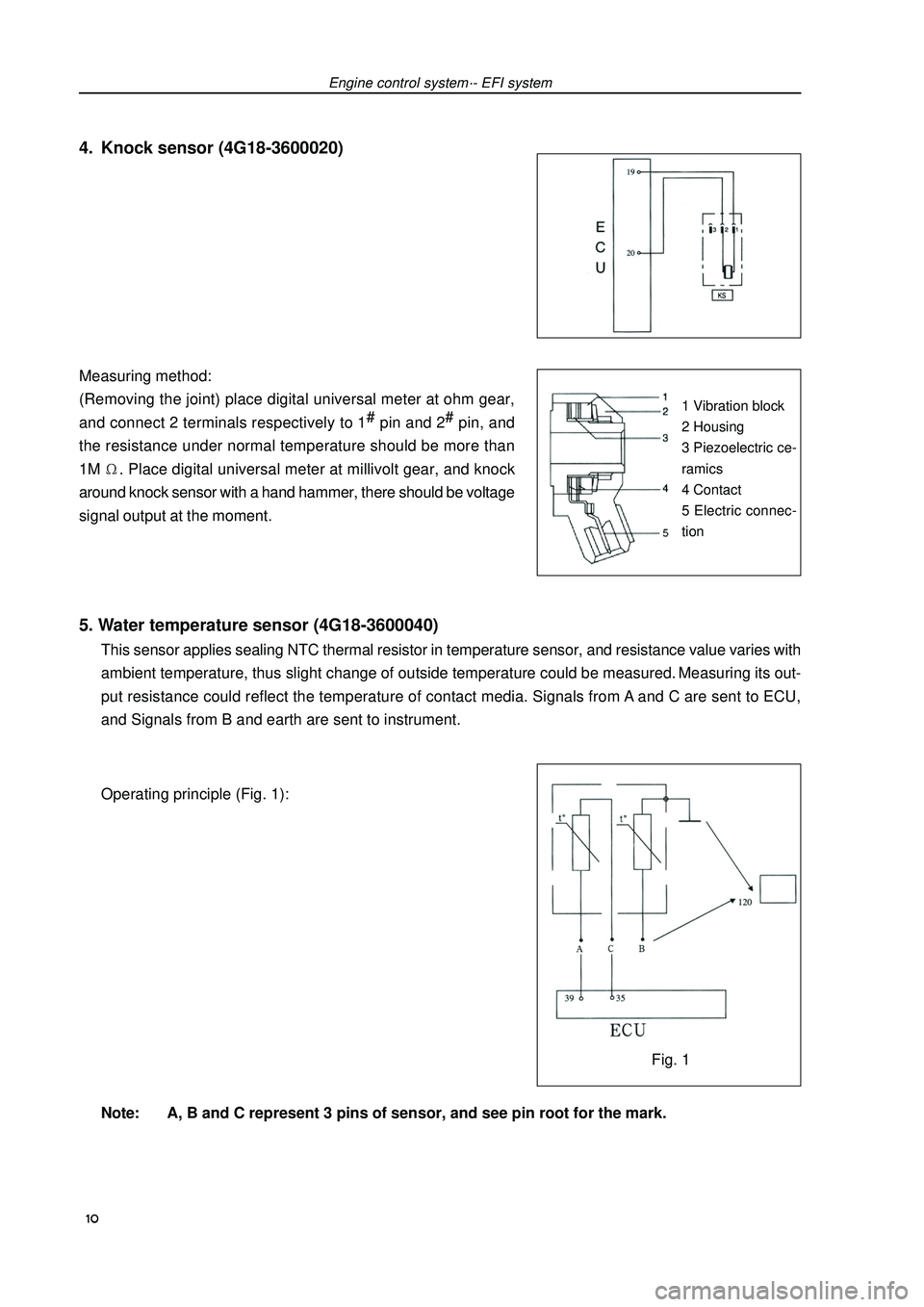
5. Water temperature sensor (4G18-3600040)This sensor applies sealing NTC thermal resistor in temperature sensor, and resistance value varies with
ambient temperature, thus slight change of outside temperature could be measured. Measuring its out-
put resistance could reflect the temperature of contact media. Signals from A and C are sent to ECU,
and Signals from B and earth are sent to instrument.
Operating principle (Fig. 1):
Note: A, B and C represent 3 pins of sensor, and see pin root for the mark. Measuring method:
(Removing the joint) place digital universal meter at ohm gear,
and connect 2 terminals respectively to 1#
pin and 2#
pin, and
the resistance under normal temperature should be more than
1M. Place digital universal meter at millivolt gear, and knock
around knock sensor with a hand hammer, there should be voltage
signal output at the moment.Engine control system·- EFI systemFig. 11 Vibration block
2 Housing
3 Piezoelectric ce-
ramics
4 Contact
5 Electric connec-
tion4. Knock sensor (4G18-3600020) 10
Page 22 of 419
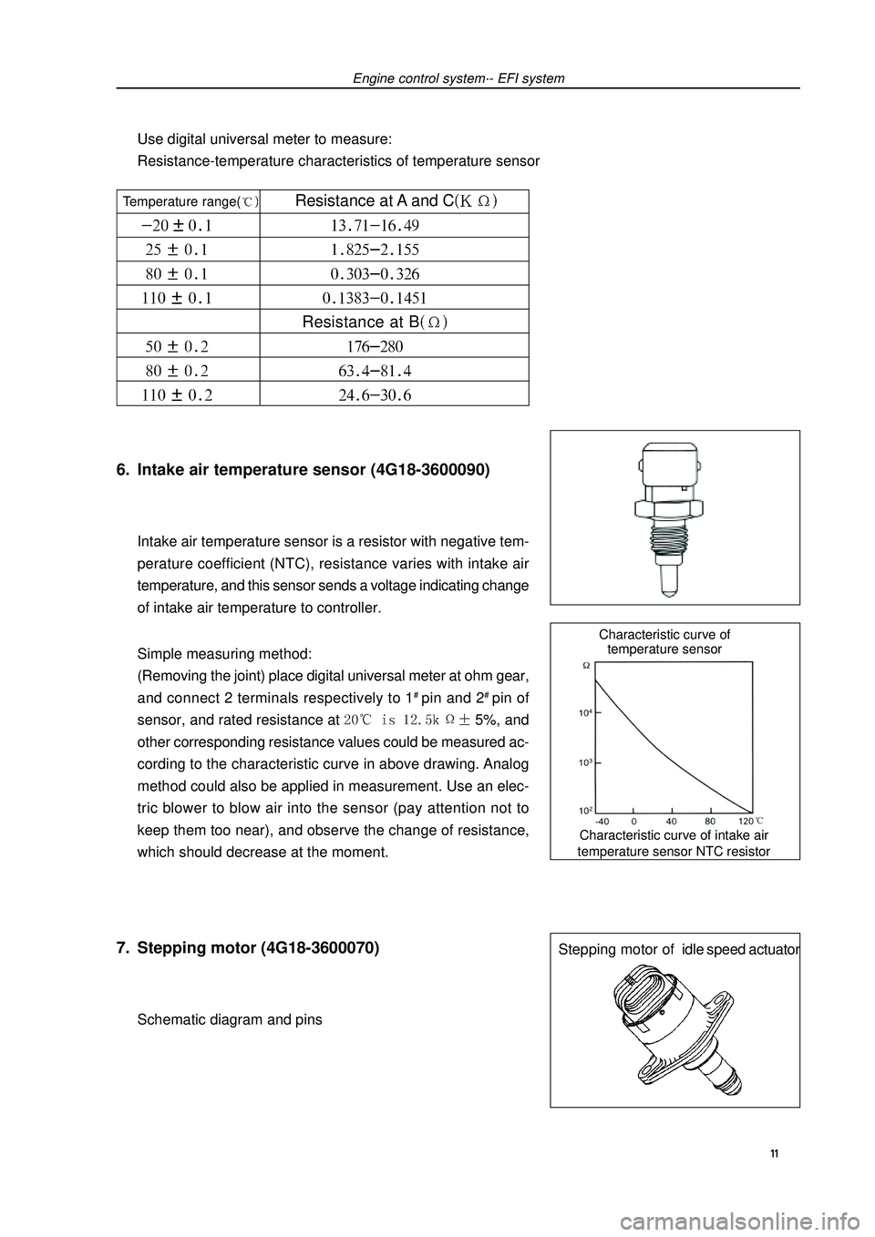
Characteristic curve of intake air
temperature sensor NTC resistorCharacteristic curve of
temperature sensorStepping motor ofidle speed actuator6. Intake air temperature sensor (4G18-3600090)Intake air temperature sensor is a resistor with negative tem-
perature coefficient (NTC), resistance varies with intake air
temperature, and this sensor sends a voltage indicating change
of intake air temperature to controller.
Simple measuring method:
(Removing the joint) place digital universal meter at ohm gear,
and connect 2 terminals respectively to 1# pin and 2# pin of
sensor, and rated resistance at 5%, and
other corresponding resistance values could be measured ac-
cording to the characteristic curve in above drawing. Analog
method could also be applied in measurement. Use an elec-
tric blower to blow air into the sensor (pay attention not to
keep them too near), and observe the change of resistance,
which should decrease at the moment.7. Stepping motor (4G18-3600070)Schematic diagram and pinsEngine control system·- EFI systemUse digital universal meter to measure:
Resistance-temperature characteristics of temperature sensor 11 Temperature range( Resistance at A and CResistance at B
Page 23 of 419
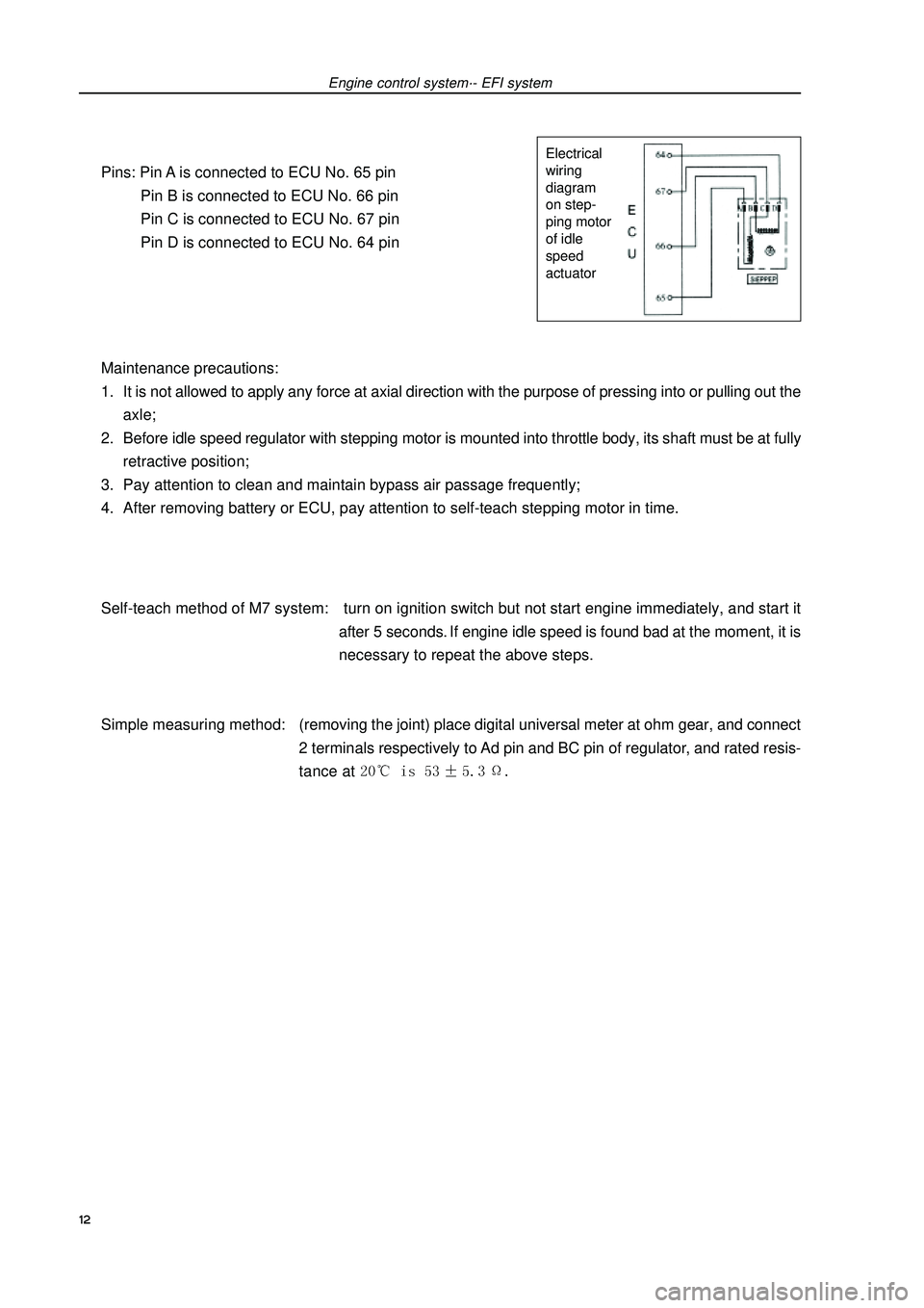
Pins: Pin A is connected to ECU No. 65 pin
Pin B is connected to ECU No. 66 pin
Pin C is connected to ECU No. 67 pin
Pin D is connected to ECU No. 64 pin
Maintenance precautions:
1. It is not allowed to apply any force at axial direction with the purpose of pressing into or pulling out the
axle;
2. Before idle speed regulator with stepping motor is mounted into throttle body, its shaft must be at fully
retractive position;
3. Pay attention to clean and maintain bypass air passage frequently;
4. After removing battery or ECU, pay attention to self-teach stepping motor in time.
Self-teach method of M7 system: turn on ignition switch but not start engine immediately, and start it
after 5 seconds. If engine idle speed is found bad at the moment, it is
necessary to repeat the above steps.
Simple measuring method:(removing the joint) place digital universal meter at ohm gear, and connect
2 terminals respectively to Ad pin and BC pin of regulator, and rated resis-
tance at Engine control system·- EFI systemElectrical
wiring
diagram
on step-
ping motor
of idle
speed
actuator12
Page 24 of 419
Engine control system·- Throttle body assemblyThrottle body assemblyRemoving, installing and disassembling, assembling1. Discharge coolant (see Page 73).
2. Remove air cleaner hose assembly.
3. Remove engine plastic hood components [4G18-1000310].
4. Remove throttle pull cable assembly.
5. remove throttle body assembly [4G18-1008240].(a) Uncouple throttle position sensor joint and stepping motor joint.
(b) Disassemble ventilation hose.
(c) Remove 2 bolts and throttle control pull cable bracket.
(d) Remove 2 preheating water inlet and outlet hoses of throttle.
(e) Remove 2 bolts and 2 nuts, and remove throttle body from intake air manifold.6. Remove stepping motor of throttle body [4G18-3600070].Remove 3 screws and stepping motor.7. Install stepping motor of throttle body.Install stepping motor.8. Install throttle body assembly.(a) Install new seal gasket on intake air manifold.
(b) Install throttle body, 2 bolts and 2 nuts.
Torque: 9. Refill coolant.
10.Check there is leakage with coolant.
13
Page 25 of 419
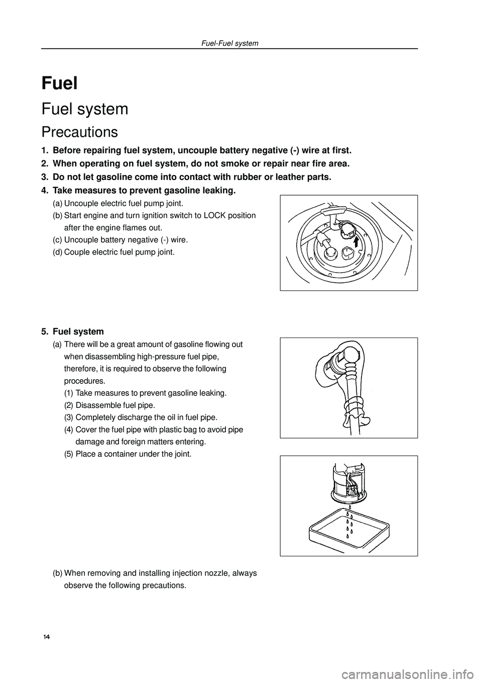
FuelFuel systemPrecautions1. Before repairing fuel system, uncouple battery negative (-) wire at first.
2. When operating on fuel system, do not smoke or repair near fire area.
3. Do not let gasoline come into contact with rubber or leather parts.
4. Take measures to prevent gasoline leaking.(a) Uncouple electric fuel pump joint.
(b) Start engine and turn ignition switch to LOCK position
after the engine flames out.
(c) Uncouple battery negative (-) wire.
(d) Couple electric fuel pump joint.5. Fuel system(a) There will be a great amount of gasoline flowing out
when disassembling high-pressure fuel pipe,
therefore, it is required to observe the following
procedures.
(1) Take measures to prevent gasoline leaking.
(2) Disassemble fuel pipe.
(3) Completely discharge the oil in fuel pipe.
(4) Cover the fuel pipe with plastic bag to avoid pipe
damage and foreign matters entering.
(5) Place a container under the joint.
(b) When removing and installing injection nozzle, always
observe the following precautions.Fuel-Fuel system 14
Page 26 of 419
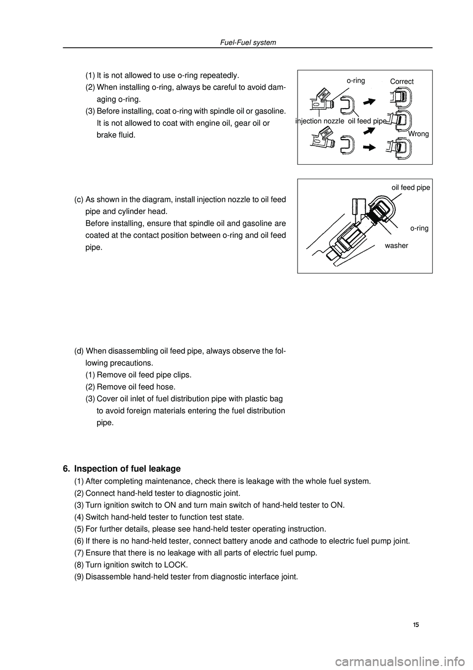
Fuel-Fuel system(1) It is not allowed to use o-ring repeatedly.
(2) When installing o-ring, always be careful to avoid dam-
aging o-ring.
(3) Before installing, coat o-ring with spindle oil or gasoline.
It is not allowed to coat with engine oil, gear oil or
brake fluid.
(c) As shown in the diagram, install injection nozzle to oil feed
pipe and cylinder head.
Before installing, ensure that spindle oil and gasoline are
coated at the contact position between o-ring and oil feed
pipe.
(d) When disassembling oil feed pipe, always observe the fol-
lowing precautions.
(1) Remove oil feed pipe clips.
(2) Remove oil feed hose.
(3) Cover oil inlet of fuel distribution pipe with plastic bag
to avoid foreign materials entering the fuel distribution
pipe.injection nozzle6. Inspection of fuel leakage(1) After completing maintenance, check there is leakage with the whole fuel system.
(2) Connect hand-held tester to diagnostic joint.
(3) Turn ignition switch to ON and turn main switch of hand-held tester to ON.
(4) Switch hand-held tester to function test state.
(5) For further details, please see hand-held tester operating instruction.
(6) If there is no hand-held tester, connect battery anode and cathode to electric fuel pump joint.
(7) Ensure that there is no leakage with all parts of electric fuel pump.
(8) Turn ignition switch to LOCK.
(9) Disassemble hand-held tester from diagnostic interface joint.15o-ringoil feed pipeoil feed pipeo-ringwasherCorrect
Wrong
Page 27 of 419
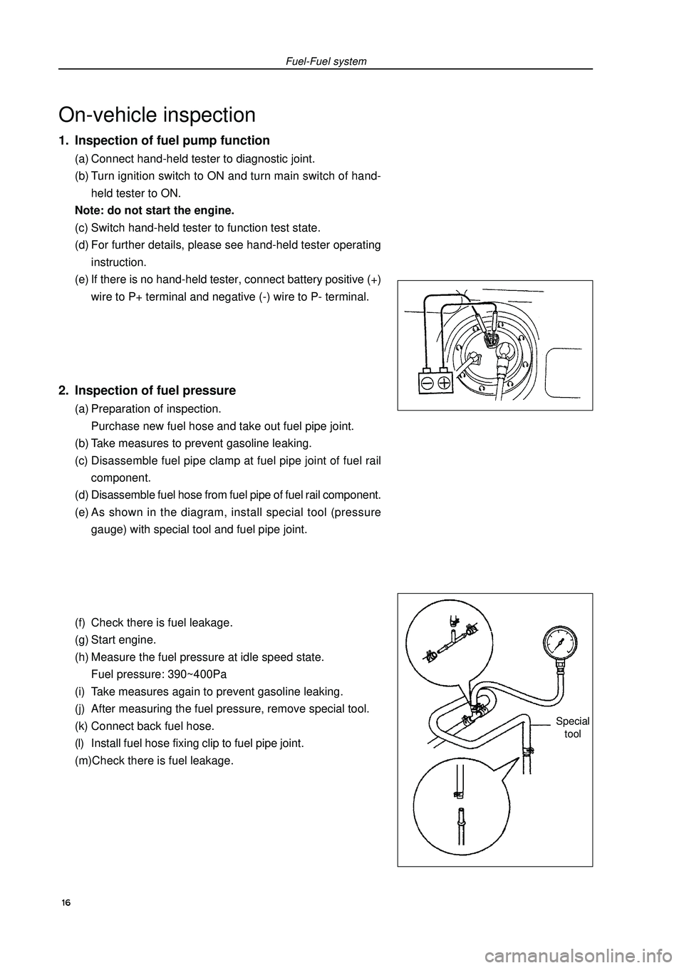
On-vehicle inspection1. Inspection of fuel pump function(a) Connect hand-held tester to diagnostic joint.
(b) Turn ignition switch to ON and turn main switch of hand-
held tester to ON.
Note: do not start the engine.
(c) Switch hand-held tester to function test state.
(d) For further details, please see hand-held tester operating
instruction.
(e) If there is no hand-held tester, connect battery positive (+)
wire to P+ terminal and negative (-) wire to P- terminal.2. Inspection of fuel pressure(a) Preparation of inspection.
Purchase new fuel hose and take out fuel pipe joint.
(b) Take measures to prevent gasoline leaking.
(c) Disassemble fuel pipe clamp at fuel pipe joint of fuel rail
component.
(d) Disassemble fuel hose from fuel pipe of fuel rail component.
(e) As shown in the diagram, install special tool (pressure
gauge) with special tool and fuel pipe joint.
(f) Check there is fuel leakage.
(g) Start engine.
(h) Measure the fuel pressure at idle speed state.
Fuel pressure: 390~400Pa
(i) Take measures again to prevent gasoline leaking.
(j) After measuring the fuel pressure, remove special tool.
(k) Connect back fuel hose.
(l) Install fuel hose fixing clip to fuel pipe joint.
(m)Check there is fuel leakage.Fuel-Fuel systemSpecial
tool 16
Page 28 of 419
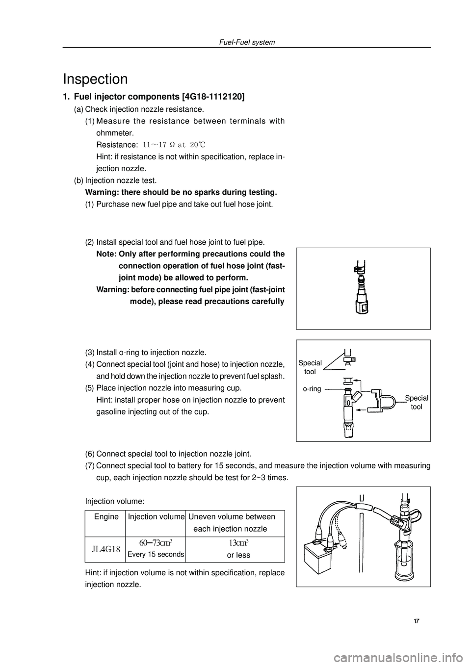
(6) Connect special tool to injection nozzle joint.
(7) Connect special tool to battery for 15 seconds, and measure the injection volume with measuring
cup, each injection nozzle should be test for 2~3 times.
Injection volume:Fuel-Fuel systemInspection1. Fuel injector components [4G18-1112120](a) Check injection nozzle resistance.
(1) Measure the resistance between terminals with
ohmmeter.
Resistance: Hint: if resistance is not within specification, replace in-
jection nozzle.
(b) Injection nozzle test.
Warning: there should be no sparks during testing.
(1) Purchase new fuel pipe and take out fuel hose joint.
(2) Install special tool and fuel hose joint to fuel pipe.
Note: Only after performing precautions could the
connection operation of fuel hose joint (fast-
joint mode) be allowed to perform.
Warning: before connecting fuel pipe joint (fast-joint
mode), please read precautions carefully
(3) Install o-ring to injection nozzle.
(4) Connect special tool (joint and hose) to injection nozzle,
and hold down the injection nozzle to prevent fuel splash.
(5) Place injection nozzle into measuring cup.
Hint: install proper hose on injection nozzle to prevent
gasoline injecting out of the cup.
Engine Injection volume Uneven volume between
each injection nozzleEvery 15 secondsor lessHint: if injection volume is not within specification, replace
injection nozzle. 17 Special
toolSpecial
toolo-ring
Page 29 of 419
![GEELY FC 2008 Owners Manual Fuel-Injection nozzle assemblyInjection nozzle assemblyReplacement1. Take measures to prevent gasoline leaking.
2. Remove engine plastic hood components.
3. Uncouple engine wire harness [4G18-3724100] GEELY FC 2008 Owners Manual Fuel-Injection nozzle assemblyInjection nozzle assemblyReplacement1. Take measures to prevent gasoline leaking.
2. Remove engine plastic hood components.
3. Uncouple engine wire harness [4G18-3724100]](/img/58/57161/w960_57161-28.png)
Fuel-Injection nozzle assemblyInjection nozzle assemblyReplacement1. Take measures to prevent gasoline leaking.
2. Remove engine plastic hood components.
3. Uncouple engine wire harness [4G18-3724100].(a) Remove injection nozzle joint.
(b) Remove exhaust gas hose.4. Remove fuel pipe assembly(a) Loosen oil feed hose clips.
(b) Pull oil feed hose away from fuse distribution pipe.
Notes:�zCheck there is dirt on fuel pipe and its joint before removing, and clean it off in the case of dirt.�zIt is only allowed to remove with hands.�zCheck there are foreign matters with the removed fuel pipe seal surface, and clean them off in the
case of foreign matters.�zCover the fuel pipe with plastic bag to avoid pipe damage and foreign matters entering.5. Remove fuel pipe assemblyRemove 2 bolts and oil feed pipe (together with injection nozzle).6. Remove injection nozzle components.Pull out 4 injection nozzles from oil feed pipe.7. Install injection nozzle components.Coat a thin layer of gasoline on o-ring and rotate left and right to push injection nozzle into oil feed pipe.
Notes:
�zBe careful not to rotate o-ring.
�zCheck injection nozzle could rotate smoothly after it is installed, and if not replace with new o-ring.8. Install fuel hose assembly.Install fuel hose to oil feed pipe.
Notes:
�zCheck there are damage or foreign matters in the binding site of fuel pipe.
�zAfter installing, pull the fuel pump with hands to check the fuel pipe is bound firmly with joint. 18
Page 30 of 419
![GEELY FC 2008 Owners Manual Fuel-Injection nozzle assembly9. Install fuel rail component [4G18-1112110].(a) Check injection nozzle o-ring and replace if there is damage.
(b) Install isolator on cylinder head.
(c) Install fuel ra GEELY FC 2008 Owners Manual Fuel-Injection nozzle assembly9. Install fuel rail component [4G18-1112110].(a) Check injection nozzle o-ring and replace if there is damage.
(b) Install isolator on cylinder head.
(c) Install fuel ra](/img/58/57161/w960_57161-29.png)
Fuel-Injection nozzle assembly9. Install fuel rail component [4G18-1112110].(a) Check injection nozzle o-ring and replace if there is damage.
(b) Install isolator on cylinder head.
(c) Install fuel rail component together with injection nozzle.
Torque:(d) Install fuel pipe fixing clip.
Torque: m10. Check the function of electric fuel pump and check there is fuel leakage.
19