wheel GEELY MK 2008 Owners Manual
[x] Cancel search | Manufacturer: GEELY, Model Year: 2008, Model line: MK, Model: GEELY MK 2008Pages: 416, PDF Size: 25.19 MB
Page 295 of 416
![GEELY MK 2008 Owners Manual MK-60 ABS system -ABS System Check5-108Fault code is 01130 7
[Description]When ABS suffers from high frequency interference of electro
magnetic wave or microprocessor thinks that GEELY MK 2008 Owners Manual MK-60 ABS system -ABS System Check5-108Fault code is 01130 7
[Description]When ABS suffers from high frequency interference of electro
magnetic wave or microprocessor thinks that](/img/58/57162/w960_57162-294.png)
MK-60 ABS system -ABS System Check5-108Fault code is 01130 7
[Description]When ABS suffers from high frequency interference of electro
magnetic wave or microprocessor thinks that input speed signal
is unauthentic, this fault code will appearPossible cause
High frequency interfer-
ence of electromagnetic
wave
Sensor is damaged or sen-
sor wiring harness is dam-
aged
ABS ECU is damagedCheck sensor output voltageReplace wheel
speed
Replace ABS ECUNoCheck sensorAbnormalCheck wiring harness
between ECU and
sensor Normal
Page 298 of 416

Whether sensor is installed correctlyInstall it correctly Yes Check sensor output voltageAbnormal
NormalCheck each sensorAbnormal
ReplaceNormal
Check gear ring of each sensorAbnormalNormalReplace
Check wheel bearing clearanceAbnormalNormalReplace or
repair
Check ABS ECU socket and
middle socket connectorAbnormalNormalReplace
socket
connector
Does fault recurNo
YesRefer to key point
for repair of oc-
casional faultRemove ABS ECU plug, check whether resis-
tance value between the following binding
posts conforms to standard value or not?
Standard value: 1.0-1.3K ohm¸
Shake sensor wiring harness and socket con-
nector while measuring
Left front: 44-45 Right front: 33-34
Left rear: 36-37 Right rear:42-43Repair wiring
harness or socket
connector NormalAbnormalReplace ABS ECUUse fault diagnosis instrument to
conduct diagnosis of hydraulic
control unitAbnormalReplace ABS HCUMK-60 ABS system -ABS System Check5-111ABS works abnormally 3
[Description] This issue is closely related to driver condition and
road surface condition, so it is not easy to conduct
fault diagnosis. However, if there is no fault code
memory, the following inspection may be conducted.Possible cause
Sensor is not installed properly
Sensor wiring harness has problem
Sensor is damaged
Gear ring is damaged
Sensor is attached with foreign
matter
Wheel bearing is damaged
ABS HCU (hydraulic pressure unit)
is damaged
ABS ECU (electric control unit) is
damaged
Page 301 of 416

Inspection item
V
V
V
V
V
Visual inspection
Visual inspection
Visual inspection
Visual inspection
V
V
ohm
k ohm
MV/Hz
MV/Hz
MV/Hz
MV/Hz Storage battery voltage (motor)
Storage battery voltage
(Solenoid valve)
Power supply insulating property
Earth insulating property
Supply voltage
ABS warning lamp
Brake light switch function pedal
is not stepped down
Brake light switch function pedal
is stepped down
Diagnostic interface
Left front wheel speed sensor
resistance value
Right front wheel speed sensor
resistance value
Left rear wheel speed sensor
resistance value
Right rear wheel speed sensor
resistance value
Left front wheel sensor output
voltage value
Right front wheel sensor output
voltage value
Left rear wheel sensor output
voltage value
Right rear wheel sensor output
voltage value
Speed sensor output voltage ratio10.1 ~ 14.5
10.1 ~ 14.5
0.00 ~ 0.5
0.00 ~ 0.5
10.1 ~ 14.5
Warning lamp goes out
Warning lamp illuminates
Warning lamp goes out
Warning lamp illuminates
for about 1.7s,then goes out
0.0 ~ 0.5
10.0 ~ 14.5
0.0 ~ 0.5
1.2 ~ 1.3
1.2 ~ 1.3
1.0 ~ 1.3
1.0 ~ 1.3
3.4 ~ 14.8
3.4 ~ 14.8
>12.2
>12.2 1-47
32-16
4-16
16-47
4-16
ECU is not
connected
Connect ECU
16-41
16-41
Diagnosis joint
K and 7
45-46
33-34
37-36
42-43
45-46
33-34
37-36
42-43 OFF
OFF
OFF
OFF
ON
OFF
ON
OFF
ON
ON
ON
OFF
OFF
OFF
OFF
OFF
OFF
OFF
OFF
OFF
Maximum peak to peak value voltage
Minimum peak to peak value voltage2III. ABS system inspectionMK-60 ABS system -ABS System Check5-114Ignition switchpositionBinding post Standard value
Unitk ohmk ohmk ohm
Page 302 of 416

Inspection item
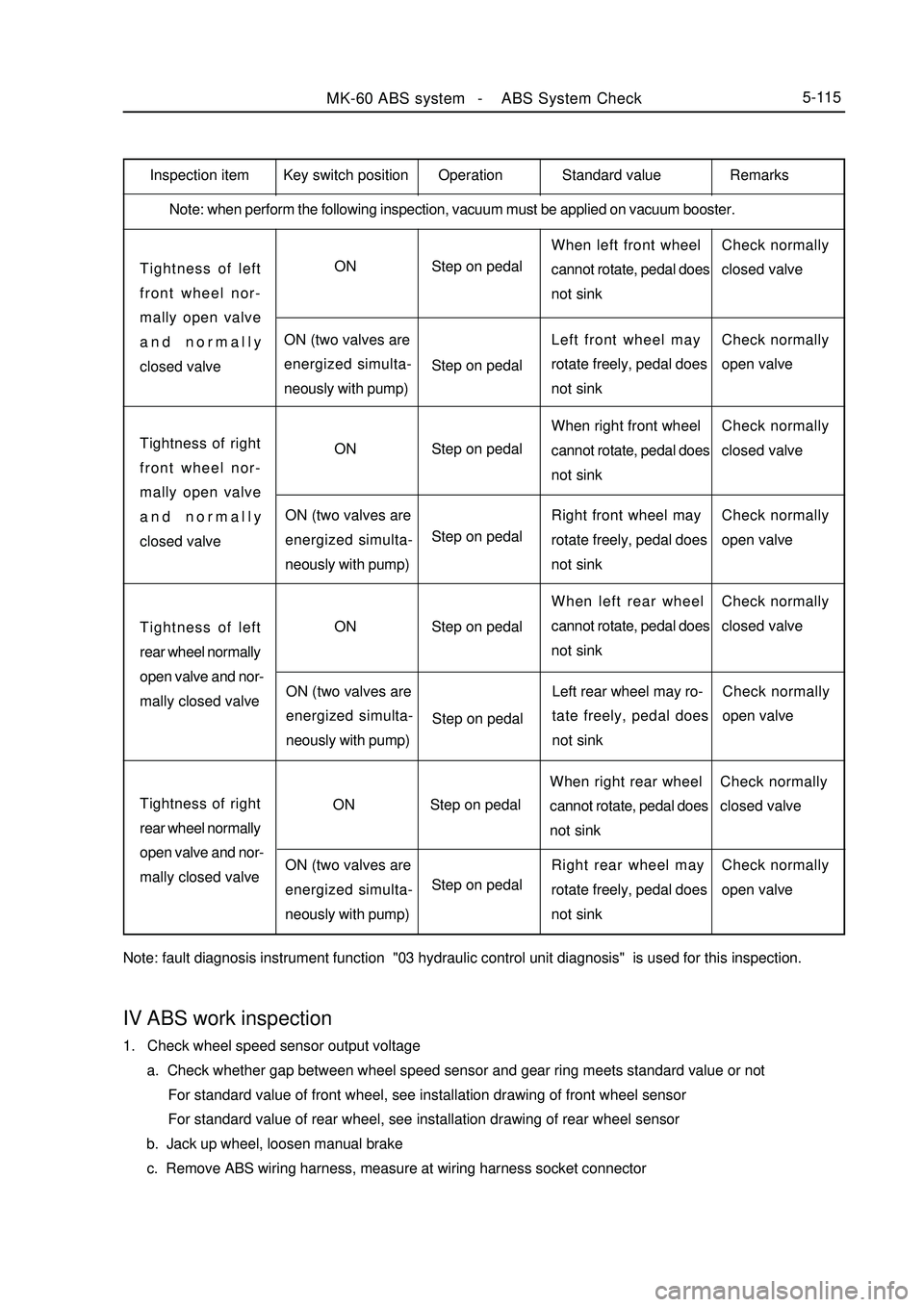
Note: when perform the following inspection, vacuum must be applied on vacuum booster.Tightness of left
front wheel nor-
mally open valve
and normally
closed valveON
ON (two valves are
energized simulta-
neously with pump)Step on pedal
Step on pedalWhen left front wheel
cannot rotate, pedal does
not sinkCheck normally
closed valve
Left front wheel may
rotate freely, pedal does
not sinkCheck normally
open valveTightness of right
front wheel nor-
mally open valve
and normally
closed valveON
ON (two valves are
energized simulta-
neously with pump)Step on pedal
Step on pedalWhen right front wheel
cannot rotate, pedal does
not sinkCheck normally
closed valve
Right front wheel may
rotate freely, pedal does
not sinkCheck normally
open valveTightness of left
rear wheel normally
open valve and nor-
mally closed valveON
ON (two valves are
energized simulta-
neously with pump)Step on pedal
Step on pedalWhen left rear wheel
cannot rotate, pedal does
not sinkCheck normally
closed valve
Left rear wheel may ro-
tate freely, pedal does
not sinkCheck normally
open valveTightness of right
rear wheel normally
open valve and nor-
mally closed valveON
ON (two valves are
energized simulta-
neously with pump)Step on pedal
Step on pedalWhen right rear wheel
cannot rotate, pedal does
not sinkCheck normally
closed valve
Right rear wheel may
rotate freely, pedal does
not sinkCheck normally
open valve
Note: fault diagnosis instrument function "03 hydraulic control unit diagnosis" is used for this inspection.MK-60 ABS system -ABS System Check5-115Key switch position Operation Standard value RemarksIV ABS work inspection1. Check wheel speed sensor output voltage
a. Check whether gap between wheel speed sensor and gear ring meets standard value or not
For standard value of front wheel, see installation drawing of front wheel sensor
For standard value of rear wheel, see installation drawing of rear wheel sensor
b. Jack up wheel, loosen manual brake
c. Remove ABS wiring harness, measure at wiring harness socket connector
Page 303 of 416

Section3 Removal and InstallationI. Precautions for removal and installation1. Firstly use diagnostic instrument to find out source of trouble, then repair.
2. Repair front prior use excluding mineral oil of detergent will surface clean Neatness ; repair when should note
before repair, use detergent without mineral oil to wipe off surface; pay attention to cleaning during repair, only
use rag without wool to wipe removed components.
3. Only use original factory spare parts, and new spare parts could only be unpacked just before installation.
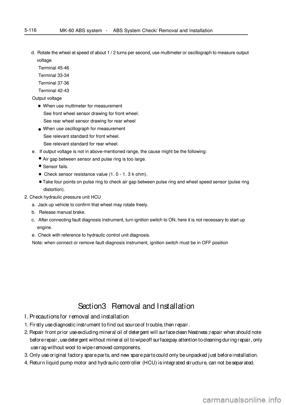
4. Return liquid pump motor and hydraulic controller (HCU) is integrated structure, can not be separated.MK-60 ABS system -ABS System Check/ Removal and Installation5-116 d. Rotate the wheel at speed of about 1 / 2 turns per second, use multimeter or oscillograph to measure output
voltage
Terminal 45-46
Terminal 33-34
Terminal 37-36
Terminal 42-43
Output voltage
When use multimeter for measurement
See front wheel sensor drawing for front wheel.
See rear wheel sensor drawing for rear wheel
When use oscillograph for measurement
See relevant standard for front wheel.
See relevant standard for rear wheel.
e. If output voltage is not in above-mentioned range, the cause might be the following:
Air gap between sensor and pulse ring is too large.
Sensor fails.
Check sensor resistance value (1. 0 - 1. 3 k ohm).
Take four points on pulse ring to check air gap between pulse ring and wheel speed sensor (pulse ring
distortion).
2. Check hydraulic pressure unit HCU
a. Jack up vehicle to confirm that wheel may rotate freely.
b. Release manual brake.
c. After connecting fault diagnosis instrument, turn ignition switch to ON, here it is not necessary to start up
engine.
e. Check with reference to hydraulic control unit diagnosis.
Note: when connect or remove fault diagnosis instrument, ignition switch must be in OFF position
Page 304 of 416

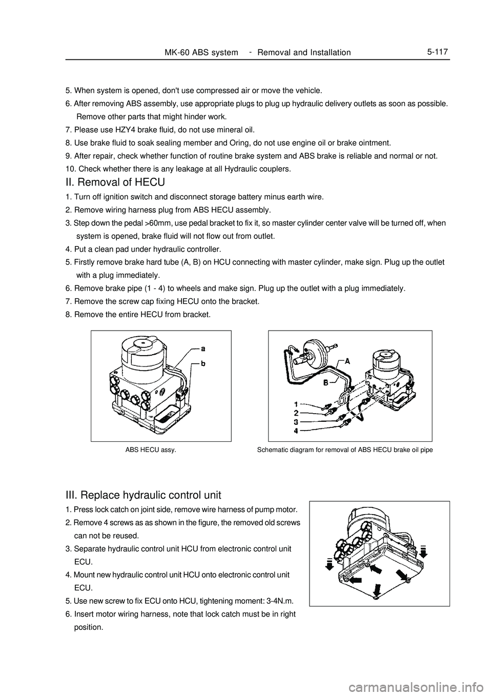
ABS HECU assy.III. Replace hydraulic control unit1. Press lock catch on joint side, remove wire harness of pump motor.
2. Remove 4 screws as as shown in the figure, the removed old screws
can not be reused.
3. Separate hydraulic control unit HCU from electronic control unit
ECU.
4. Mount new hydraulic control unit HCU onto electronic control unit
ECU.
5. Use new screw to fix ECU onto HCU, tightening moment: 3-4N.m.
6. Insert motor wiring harness, note that lock catch must be in right
position.MK-60 ABS system -
Removal and Installation5-117Schematic diagram for removal of ABS HECU brake oil pipe5. When system is opened, don't use compressed air or move the vehicle.
6. After removing ABS assembly, use appropriate plugs to plug up hydraulic delivery outlets as soon as possible.
Remove other parts that might hinder work.
7. Please use HZY4 brake fluid, do not use mineral oil.
8. Use brake fluid to soak sealing member and Oring, do not use engine oil or brake ointment.
9. After repair, check whether function of routine brake system and ABS brake is reliable and normal or not.
10. Check whether there is any leakage at all Hydraulic couplers.II. Removal of HECU1. Turn off ignition switch and disconnect storage battery minus earth wire.
2. Remove wiring harness plug from ABS HECU assembly.
3. Step down the pedal >60mm, use pedal bracket to fix it, so master cylinder center valve will be turned off, when
system is opened, brake fluid will not flow out from outlet.
4. Put a clean pad under hydraulic controller.
5. Firstly remove brake hard tube (A, B) on HCU connecting with master cylinder, make sign. Plug up the outlet
with a plug immediately.
6. Remove brake pipe (1 - 4) to wheels and make sign. Plug up the outlet with a plug immediately.
7. Remove the screw cap fixing HECU onto the bracket.
8. Remove the entire HECU from bracket.
Page 316 of 416

Chapter 10 On-board Vehicle TelephoneI. Key points for use of Geely hands-free car telephone: 1. Microphone of hands-free car telephone is installed on the back of steering wheel upright column, away from
driver to ensure talking effect. During talking, do not open window, otherwise noisy wind might influence talking
effect.
2. Since there are many kinds of mobile phones in Chinese market, in order to ensure talking effect, please
select interface line corresponding to your mobile phone, otherwise talking effect might be influenced. At present,
Nokia, Motorola, Siemens interface lines are available.
3. To use, insert one end of mobile phone interface line into 8 core RJ 45 stand on automobile panel, connect
the other end to earphone output port of the mobile phone. When mobile phone is not connected, automobile sound
works normally, when mobile phone receive a call, CD becomes quiet automatically, at the same time, loudspeaker
in the vehicle is switched to hands-free telephone output. This hands-free car telephone is provided with response
button at the top of microphone, however, new style of mobile phone does not support manual response function
for the time being, while supports automatic response function, namely it receive the call automatically after
ringing for three times.
4. After talking is finished, automobile sound will return to original state automatically.
5. During daily use, note that contact insertion and withdraw force of mobile phone interface line should not
be too large, so as to avoid damage.
6. Hands-free car telephone has no volume switch, volume of loudspeaker voice may be adjusted by regulating
the volume of handset earphone.II. Circuit diagram5-129On Board Vehicle Telephone-On-board Vehicle TelephonePlease Refer to "MK WIRING DIAGRAM"
Page 337 of 416

Interior & Exterior Trim and Accessory -Front Seat Belt6-8VI. Attentions:
1. Before mounting, you must check if the product is damaged, cracked or rusted.
2. Place the retractor on the vertical position before pulling out the strap. Check if the strap can be easily pulled
out and rotated and the retractor can be locked.
3. When installing a pretensioning seat belt, check if the emitter head pin deflects and is rusted, etc. The emitter
in the pre-tensioning seat belt can work for 15 years.
4. Check if the buckle lock and connection piece comply with the connection of the car. And check if the buckle
can be opened easily.
5. When fitting the bolts, check if the threads on the nut of coating are clear. Those with welding slag must be
cleaned before fitting the bolts.
6. After pulling out the strap of retractor, no barrier (such as wiring harness, etc.) around the strap is allowed. If
there is, it is necessary to get rid of the barrier to ensure the force of retractor and that the strap is not scratched.
VII. How to handle with scraped seat belt
Tips:
Scrap seat belt provided with pre-tensioner, you have to trigger the pre-tensioner taking the following steps.
1. Check if the storage battery is above 12 V on its positive and negative poles;
2. Check the energizing tool;
Warning:
When energizing the pre-tensioner of seat belt, be sure to use dedicated energizing tool for the pre-tensioner
of seat belt.
3. Connect the special tool with the storage battery and also connect
the red clip on the special tool with the positive terminal of the battery
and connect the black clip with the negative terminal of the battery;
4. If the front seat belt is on the car body and is not taken off,
disconnect the joint of the pre-tensioner of seat belt;
5. Connect the yellow joint of the special tool with the joint of the
pre-tensioner of seat belt;
6. At 10 meter away from seat belt, use a special tool to trigger theAbove 10 meterpre-tensioner of seat belt.
Warning:
a. Ensure that there be no people within 10 meters from the seat
belt;
b. If the seat belt has already been taken down from the car, it is
necessary to cover it using the car wheel with tire to avoid injury.
c. When triggering, explosion will emit loud sound. So it shall be
done outdoors without disturbing local community.
d. When you hold the triggered seat belt, be sure to wear gloves
and goggles.
e. After you have finished the operation, you must wash your hands.
f. Do not pour water, etc. to the energized seat belt pre-tensioner.
7. Place the already triggered seat belt into the ethylene bag and tighten it as you do with other articles.
Warning:
a. Do not dispose untriggered seat belt at will.
b. When the pre-tensioner of seat belt is triggered, the seat belt assembly would be very hot. Therefore, you
cannot touch it until at least 30 minutes after it is triggered.
Page 343 of 416

6-14 e. Pull the instrument panel sub-assembly backward and then take it out.
10. Remove the instrument panel lower housing assembly
Loosen 6 clasps and then pull the lower housing assembly out.
11. Remove the radio set assembly with bracket
a. Unfix 4 screws;
b. Disconnect the connector and then unfasten the radio set
assembly with bracket.
12. Remove the horn button assembly
13. Remove the steering wheel assembly
14. Remove the steering column upper cover assembly
15. Remove the steering column lower cover assembly
16. Remove the cupholder
17. Remove the auxiliary fasia console assembly
a. Unfix 3 screws;
b. Unfix 3 clips by use of a clip remover and then unfasten the
auxiliary fasia console assembly.6 clasps
2 clamps
2 clipsInterior & Exterior Trim and Accessory -Dashboard, Middle Console and Instrument Panel
Page 373 of 416

Part VII BodyChapter 1 SurveySection 1 Body StructureThe body is made up of main structure, movable plate work, interior/exterior trim parts, and body accessories.I. Main StructureAs shown in Fig.5-1, the main structure is made up of various assemblies and parts including engine compartment
assembly & front wall parts, floor assembly, left/right wall assembly, rear wall assembly, roof assembly and
luggage compartment main cover assembly etc.Fig. 5-1 Main Structure
1 Engine compartment assembly & front wall parts 2. Left/right wall assembly
3. Luggage compartment main cover assembly 4. Rear wall assembly 5. Floor assembly
6. Roof assembly 7. Front cross beam assembly(1) Engine Compartment Assembly & Front Wall Parts The main function of the engine compartment assembly and front wall parts is to form an engine compartment
and absorb most energy generated when the vehicle is collided from the front. The compartment provides a hood
for the engine and its accessories, which can prevent the front wheel from throwing mud. In the appearance, it
represents the body's design requirements. As shown in Fig.5-2, the engine compartment assembly and front wall
parts include front cross beam assembly, left/right longitudinal beam assembly, radiator cross beam assembly,Body -Survey7-1
123456
7