GEELY MK 2008 Service Manual
Manufacturer: GEELY, Model Year: 2008, Model line: MK, Model: GEELY MK 2008Pages: 416, PDF Size: 25.19 MB
Page 41 of 416
2-20 (3) Long time exposure to sun damages interior. So it is better to use covers on upper seat backs, and rear
separation board that are exposed to sun.
8. Maintenance of body exterior
Body exterior is to keep body cleanness and brightness to give the impression of beauty and comfort, and to avoid
rust and abnormal paint peeling off. The key points of body maintenances are:
(1) Wash body using the method below:
a. Wash the dirty things off the body by pressurized water, and then clean the body with
soft cloth of sponge from up to down.
b. Dry body surface with good white cloth. Apply brake pedal several times when driving
after the car is washed to get rid of water in braking system.
c. Do not wipe the body when it is dry. Do not clean paint surface and glass with gasoline,
coal oil, narkosid, strong lye or alcohol.
(2) Cleaning windshield glass
Do not use silicon-bronze radical products. To get better cleaning effects, use special glass cleanser.
(3) Cleaning asphalt on the body
Do not peel the asphalt off from body or bumper, but use special cleanser
(4) Paint
Scratches or slight damages can be fixed with special paint spray. It dries in the air.
(5) Cleaning exterior decoration parts and aluminum parts. Wash with water with soap fluid or cleanser, and wash with clean water. To keep the gloss of painted surface,
wax on the surface after it is dry. (6) Polish and wax the body paint polishing and waxing keeps the body bright and pretty, and protects the paint
as well.
a. Polish in winter. Make sure the vehicle body is absolutely clean and dry before
polishing, polish with fluid or milky wax.
b. Vehicle body must be absolutely dry and clean before waxing. Use waxing tools (soft
table tissue or smooth cotton cloth) to cover the body paint surface evenly with wax.
Check if the vehicle body is covered by wax: spray some water onto the paint surface,
if water drops are formed, that surface is waxed, otherwise, clean the surface and wax
it again. Attention: do not wax under sun, or in cold weather.
Attention
1) When using high pressure washing machine, do not point the washing sprayer to transmission, steering
mechanism and other rubber protection parts, or exterior decoration parts, roof welding lines, heat radiator
or engine compartment.
2) The bottom of vehicle body is made of anti-corrosion material,and has been through anti-corrosion process.
After the vehicle has been running frequently on roads de-frozen with salt for some time, clean engine
compartment and lower part of vehicle body and take some protection actions.Usage and Maintenance of MK Series - Daily Maintenance of MK Sedan
Page 42 of 416
Part III EngineChpater 1 Engine AssemblyInformation about engine accessories in MK-1 Car Maintenance Manual deals with only that concerned with a
complete car. Please refer to separated Maintenance Manual for information about the engine body. Engines
concerned are MR479Q, MR479QA and MR481QA.Section 1 Engine Inspection1. Check the engine oil
(1) Check the oil level.
(2) Start the engine, and reach warm-up temperature.
(3) Shut the engine down, wait for 3-5min, and check the oil level.
(4) Check whether the oil level is in within the range marked by the scale; if it is lower than the limit (mark
L), fill oil to mark F.
(5) Keep the oil clean without any coolant or petrol mixed in and with appropriate viscosity.
2. Change oil.
(1) Start the engine. When normal temperature is reached, shut down the engine.
(2) Open the oil cap, remove the oil drain plug, and drain the oil.
(3) Tighten the oil drain plug to a specified torque 54N.m.
(4) Fill fresh oil into the crank case with oil quantity 2.8L in case of the filter not changed, 3.0L in case of the
filter changed and 3.5L in case of the dry filter.
(5) Fit on the oil filling cap.
(6) Start the engine.
(7) Shut down the engine and check the oil quantity, and fill oil to the mark F on the oil scale if necessary.
3. Replace the oil filter.
(1) Remove the oil filter.
(2) Before mounting the oil filter, apply a small quantity of engine oil to the O-ring of the new oil filter.
(3) Tight the oil filter to a specified torque (12.7N.m).
(4) Start the engine, and check whether there is any leakage
(5) Shut down the engine, check the oil quantity and fill as required.
4. Oil selection
Oil over PAI SG grade is preferred.
SAE10W-30 or SAE10W-40 is preferred, and ASE5W-30 is used in cold region in the winter.
Note: For the best effect and the greatest safety, it is advisable to use the following lubrication oil.
a. Meet the requirements of API level.
b. Select proper SAE viscosity rating within expected ambient temperature.
The lubrication oil that can not meet the requirements of SAE viscosity and API label at the same time is not
allowed.
5. Check the coolant.
(1) After the engine is cooled down, remove the radiator cover.EngineEngine Assembly3-1 -
Page 43 of 416
TableEngine AssemblyEngine Inspection3-2 Note:
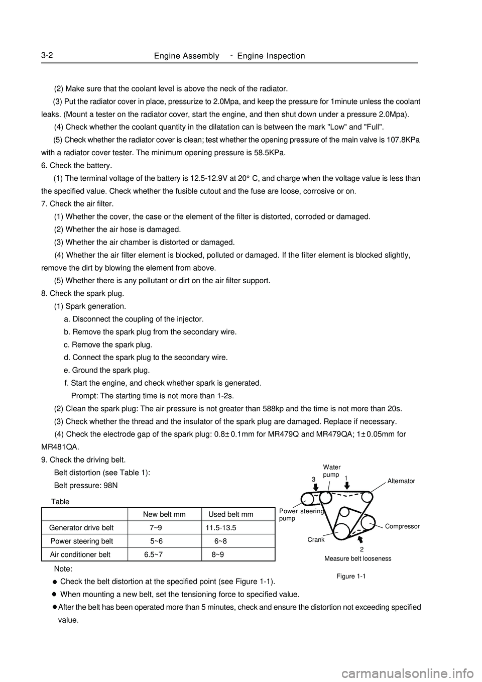
Check the belt distortion at the specified point (see Figure 1-1).
When mounting a new belt, set the tensioning force to specified value.
After the belt has been operated more than 5 minutes, check and ensure the distortion not exceeding specified
value. (2) Make sure that the coolant level is above the neck of the radiator.
(3) Put the radiator cover in place, pressurize to 2.0Mpa, and keep the pressure for 1minute unless the coolant
leaks. (Mount a tester on the radiator cover, start the engine, and then shut down under a pressure 2.0Mpa).
(4) Check whether the coolant quantity in the dilatation can is between the mark "Low" and "Full".
(5) Check whether the radiator cover is clean; test whether the opening pressure of the main valve is 107.8KPa
with a radiator cover tester. The minimum opening pressure is 58.5KPa.
6. Check the battery.
(1) The terminal voltage of the battery is 12.5-12.9V at 20°C, and charge when the voltage value is less than
the specified value. Check whether the fusible cutout and the fuse are loose, corrosive or on.
7. Check the air filter.
(1) Whether the cover, the case or the element of the filter is distorted, corroded or damaged.
(2) Whether the air hose is damaged.
(3) Whether the air chamber is distorted or damaged.
(4) Whether the air filter element is blocked, polluted or damaged. If the filter element is blocked slightly,
remove the dirt by blowing the element from above.
(5) Whether there is any pollutant or dirt on the air filter support.
8. Check the spark plug.
(1) Spark generation.
a. Disconnect the coupling of the injector.
b. Remove the spark plug from the secondary wire.
c. Remove the spark plug.
d. Connect the spark plug to the secondary wire.
e. Ground the spark plug.
f. Start the engine, and check whether spark is generated.
Prompt: The starting time is not more than 1-2s.
(2) Clean the spark plug: The air pressure is not greater than 588kp and the time is not more than 20s.
(3) Check whether the thread and the insulator of the spark plug are damaged. Replace if necessary.
(4) Check the electrode gap of the spark plug: 0.8±0.1mm for MR479Q and MR479QA; 1±0.05mm for
MR481QA.
9. Check the driving belt.
Belt distortion (see Table 1):
Belt pressure: 98NMeasure belt loosenessCompressor
Crank Power steering
pumpWater
pump
Alternator2 1
3Figure 1-1New belt mm Used belt mm
Generator drive belt 7~9 11.5-13.5
Power steering belt 5~6 6~8
Air conditioner belt 6.5~7 8~9 -
Page 44 of 416
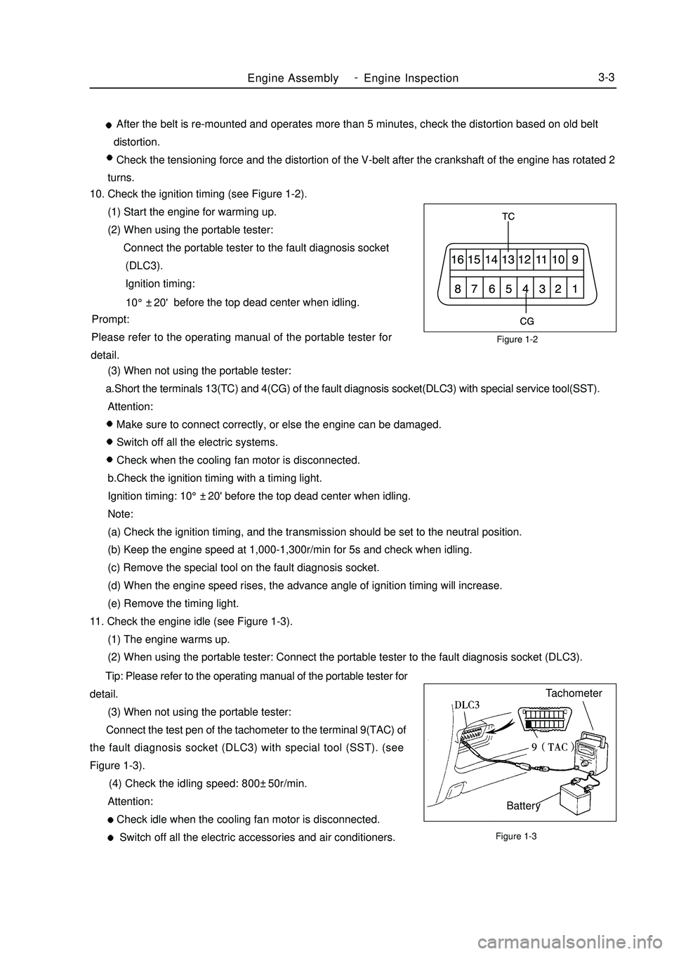
Figure 1-2
Figure 1-3Engine AssemblyEngine Inspection3-3 After the belt is re-mounted and operates more than 5 minutes, check the distortion based on old belt
distortion.
Check the tensioning force and the distortion of the V-belt after the crankshaft of the engine has rotated 2
turns.
10. Check the ignition timing (see Figure 1-2).
(1) Start the engine for warming up.
(2) When using the portable tester:
Connect the portable tester to the fault diagnosis socket
(DLC3).
Ignition timing:
before the top dead center when idling.
Prompt:
Please refer to the operating manual of the portable tester for
detail.
(3) When not using the portable tester:
a.Short the terminals 13(TC) and 4(CG) of the fault diagnosis socket(DLC3) with special service tool(SST).
Attention:
Make sure to connect correctly, or else the engine can be damaged.
Switch off all the electric systems.
Check when the cooling fan motor is disconnected.
b.Check the ignition timing with a timing light.
Ignition timing: 10°±20' before the top dead center when idling.
Note:
(a) Check the ignition timing, and the transmission should be set to the neutral position.
(b) Keep the engine speed at 1,000-1,300r/min for 5s and check when idling.
(c) Remove the special tool on the fault diagnosis socket.
(d) When the engine speed rises, the advance angle of ignition timing will increase.
(e) Remove the timing light.
11. Check the engine idle (see Figure 1-3).
(1) The engine warms up.
(2) When using the portable tester: Connect the portable tester to the fault diagnosis socket (DLC3).
Tip: Please refer to the operating manual of the portable tester for
detail.
(3) When not using the portable tester:
Connect the test pen of the tachometer to the terminal 9(TAC) of
the fault diagnosis socket (DLC3) with special tool (SST). (see
Figure 1-3).
(4) Check the idling speed: 800±50r/min.
Attention:
Check idle when the cooling fan motor is disconnected.
Switch off all the electric accessories and air conditioners.Tachometer
Battery10°±20' -
Page 45 of 416

12. Check the compressing pressure (see Figure 1-4).
(1) Warm up and switch off the engine.
(2) Remove the secondary wire.
(3) Remove the spark plug.
(4) Check the compressing pressure in the cylinder.
a.Insert the pressure gauge into the spark plug bore.
b. Throttle widely opens.
c. Rotate the engine crankshaft and measure the compressing
pressure (see Table 2).Figure 1-4Table 2Cylinder compressing pressure (KPa)Pressure difference range of cylinders of this model (KPa)Minimum compressing pressure (KPa)MR479Q MR479QA MR481QA
1250 1320 1360
100
980
Attention:
The electric quantity in the battery should be always enough, and the engine speed should be not less than
250r/min.
Check the compressing pressure in other cylinders in the same way.
Measure as soon as possible.
(5) If the compressing pressure in more than one cylinder is relatively low, fill a bit engine oil to the cylinder
through the spark plug bore, and repeat step a to c to check.
Tip:
If the compressing pressure is increased after the oil is filled, the piston ring or the cylinder may be worn or
damaged.
If the pressure is still low, the valve may be jammed or badly sealed, or the washer may be leaked.
13. Check CO/HC.
(1) Start the engine.
(2) Keep the engine running at a speed of 2500 r/min for about 180s.
(3) During idling, insert the test bar of CO/HC instrument into the exhaust pipe about 40cm depth at least.
(4) Check the concentration of emission of CO/HC at idle speed and at a speed of 2500 r/min respectively.
Tip:
Measure within 3 minutes.
Test the concentration of emission and lambda value of CO/HC at idle speed and at a speed of 2500 r/min
respectively according to GB18352.3-2005 standard.
(5) If the concentration of CO/HC is not up to standard, carry out fault diagnosis by following the steps below.
(1) Check oxygen sensor.
(2) Refer to Table 3 to find possible causes, check and repair.Engine AssemblyEngine Inspection3-4 -
Page 46 of 416

Table 3Section 2 Removal of the Engine Assembly from the Vehicle1. Avoid petrol overflowing (Disconnect from the fuel tank).
2. Remove the front wheel.Figure 1-5Engine AssemblyRemoval of the Engine Assembly from the Vehicle3-5CO
Normal
Low
HighHC
High
High
HighProblems
Bad idle speed
Bad idle speed
(HC reading fluctuates)
Bad idle speed
(Black smoke exhausts)Causes
1. Ignition fault:
Incorrect ignition timing;
Dirt, short circuit, or incorrect spark plug gap.
2. Incorrect valve gap.
3. Suction and exhaust valve leak.
4. Cylinder leaks.
1. Vacuum leaks.
PCV pipe . manifold;
Idle speed control valve;
Brake booster pipeline.
2. Spark lacks since the mixed gas is too thin.
1. Air filter is blocked.
2. PCV valve is blocked.
3. EFI system fails.
ECU fails.
Pressure regulator of fuel oil is out of order.
Water temperature sensor does not work.
Suction pressure/temperature sensor fails.
Injector fails.
The throttle position sensor fails.3. Discharge the coolant completely.
4. Remove the air filter assembly with hose (see Figure 1-5).
(1) Disconnect the joint of the temperature sensor and the wire
plug.
(2) Disconnect the vent duct from the hose of the air filter.
(3) Release the wire clip bolt on the air filter.
(4) Disconnect the hose of the air filter from the throttle body.
(5) Remove 3 bolts and the air filter assemblies.
5. Remove the battery.
6. Remove the fuel pipe sub-assembly.
7. Disconnect the water pipe; disconnect the water outlet pipe of the
heater from the air conditioner pipe.
8. Release the nut and remove the accelerator control cable. -
Page 47 of 416
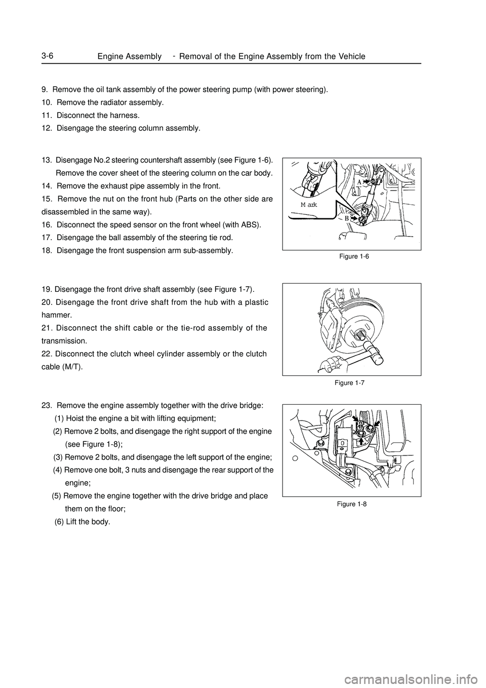
Figure 1-7Figure 1-6
Figure 1-8Engine AssemblyRemoval of the Engine Assembly from the Vehicle3-69. Remove the oil tank assembly of the power steering pump (with power steering).
10. Remove the radiator assembly.
11. Disconnect the harness.
12. Disengage the steering column assembly.
13. Disengage No.2 steering countershaft assembly (see Figure 1-6).
Remove the cover sheet of the steering column on the car body.
14. Remove the exhaust pipe assembly in the front.
15. Remove the nut on the front hub (Parts on the other side are
disassembled in the same way).
16. Disconnect the speed sensor on the front wheel (with ABS).
17. Disengage the ball assembly of the steering tie rod.
18. Disengage the front suspension arm sub-assembly.
19. Disengage the front drive shaft assembly (see Figure 1-7).
20. Disengage the front drive shaft from the hub with a plastic
hammer.
21. Disconnect the shift cable or the tie-rod assembly of the
transmission.
22. Disconnect the clutch wheel cylinder assembly or the clutch
cable (M/T).
23. Remove the engine assembly together with the drive bridge:
(1) Hoist the engine a bit with lifting equipment;
(2) Remove 2 bolts, and disengage the right support of the engine
(see Figure 1-8);
(3) Remove 2 bolts, and disengage the left support of the engine;
(4) Remove one bolt, 3 nuts and disengage the rear support of the
engine;
(5) Remove the engine together with the drive bridge and place
them on the floor;
(6) Lift the body.Mark -
Page 48 of 416
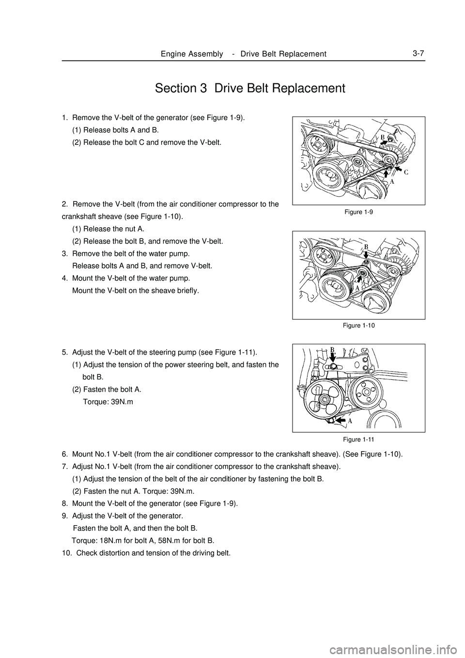
Section 3 Drive Belt Replacement1. Remove the V-belt of the generator (see Figure 1-9).
(1) Release bolts A and B.
(2) Release the bolt C and remove the V-belt.
2. Remove the V-belt (from the air conditioner compressor to the
crankshaft sheave (see Figure 1-10).
(1) Release the nut A.
(2) Release the bolt B, and remove the V-belt.
3. Remove the belt of the water pump.
Release bolts A and B, and remove V-belt.
4. Mount the V-belt of the water pump.
Mount the V-belt on the sheave briefly.
5. Adjust the V-belt of the steering pump (see Figure 1-11).
(1) Adjust the tension of the power steering belt, and fasten the
bolt B.
(2) Fasten the bolt A.
Torque: 39N.mFigure 1-9
Figure 1-10
Figure 1-11Engine AssemblyDrive Belt Replacement3-76. Mount No.1 V-belt (from the air conditioner compressor to the crankshaft sheave). (See Figure 1-10).
7. Adjust No.1 V-belt (from the air conditioner compressor to the crankshaft sheave).
(1) Adjust the tension of the belt of the air conditioner by fastening the bolt B.
(2) Fasten the nut A. Torque: 39N.m.
8. Mount the V-belt of the generator (see Figure 1-9).
9. Adjust the V-belt of the generator.
Fasten the bolt A, and then the bolt B.
Torque: 18N.m for bolt A, 58N.m for bolt B.
10. Check distortion and tension of the driving belt. -
Page 49 of 416

Chapter 2 Engine MechanicalSection 1 Engine ComponentsComponent ViewFigure 2-1Engine MechanicalEngine Components3-8Upside of radiator support
Engine cover lock assembly
Starter assembly
Output pipe of oil cooler
Input pipe of oil coolerTransmission control cable assembly Fuel oil sub-assembly Accelerator control cable assemble
Water inlet pipe of heater
Water outlet pipe of heaterTransmission control cable assemblySuitable for 1.5L/1.6L(Tight coupling)Suitable for 1.3L/1.5L(Non-tight coupling) Radiator assemblyAir filter assembly with hose
Clutch release assembly
Water inlet pipe of radiator
Water outlet pipe of radiator
Battery -
Page 50 of 416
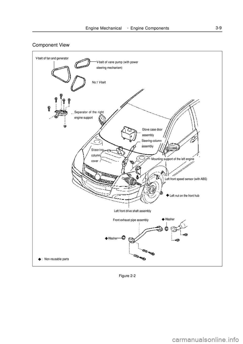
Component ViewFigure 2-2Engine MechanicalEngine Components3-9V-belt of fan and generator
V-belt of vane pump (with power
steering mechanism)
No.1 V-belt
Glove case door
assemblyFront exhaust pipe assemblySeparator of the right
engine support: Non-reusable partsLeft front drive shaft assemblyLeft nut on the front hubSteering
column
coverSteering column
assembly
Mounting support of the left engineLeft front speed sensor (with ABS)
Washer
Washer -