ignition GEELY MK 2008 Service Manual
[x] Cancel search | Manufacturer: GEELY, Model Year: 2008, Model line: MK, Model: GEELY MK 2008Pages: 416, PDF Size: 25.19 MB
Page 254 of 416

5-67Notice
When connecting or disconnecting the turn the ignition switch OFF first.
d. Turn the ignition switch ON.
e. Read the diagnostic circuit and see if the other locations than the troubled area of the airbag are normal.
f. Turn the ignition switch OFF.
g. Remove the negative (-) terminal cable from the battery, and protect it with insulating tape for insulation.Notice
Work must be started 60s after the negative (-) terminal cable is disconnected from battery.
(2) Installation of clock spring
Screw up the clock spring clockwise to the end, rotate it counter-
clockwise by 2.5 turns, and align it with the mark (see the figure 3).Notice
If the center of the clock spring cannot be aligned, the steering
wheel will not turn midway, or cause bad performance to the clock
spring circuit, consequently hamper the normal action of the airbag.
(3) Installation of the components of the steering wheel and airbag assembly
a. When the center of the clock spring is aligned, install the components of the steering wheel and airbag
assembly.
b. After being installed, rotate the left and right sides of the steering wheel to position, and make sure there
is no abnormality.
(4) Check after installation
a. Slightly rotate the steering wheel left and right, make sure that there is no abnormality or noise. (Driver
airbag module, clock spring)
b. Turn the ignition switch ON.
c. The warning light goes on within 4s, and then goes out.figure 3SRS (Supplemental Restraint System)-
SRS-General Information b. Connect negative (-) terminal cable of the battery.
c. Connect the diagnostic connector (16 pins).Notice
In case of scrapping an airbag, it shall be noted that the airbag shall be deployed according to the specified
procedures before being scrapped.SRS Air Bag
Warning LightNotice
When installing the components of the steering wheel and
airbag assembly, attention should be given to protect the wire
harness of the clock spring from seizure.
d. The trouble shall be eliminated if the warning light remains on when the ignition switch is turned on or
after it goes out after 4s.
Page 286 of 416
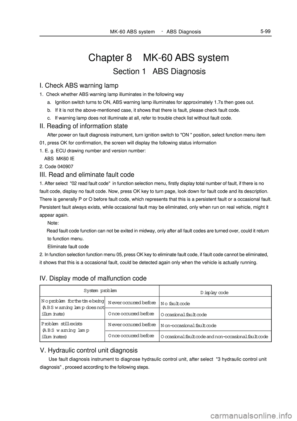
System problem
No problem for the time being
(ABS warning lamp does not
illuminate)Never occurred before
Once occurred before
Never occurred before
Once occurred before Problem still exists
(ABS warning lamp
illuminates)Chapter 8 MK-60 ABS systemSection 1 ABS DiagnosisV. Hydraulic control unit diagnosis Use fault diagnosis instrument to diagnose hydraulic control unit, after select "3 hydraulic control unit
diagnosis" , proceed according to the following steps.MK-60 ABS system -
ABS Diagnosis5-99I. Check ABS warning lamp1. Check whether ABS warning lamp illuminates in the following way
a. Ignition switch turns to ON, ABS warning lamp illuminates for approximately 1.7s then goes out.
b. If it is not the above-mentioned case, it shows that there is fault, please check fault code.
c. If warning lamp does not illuminate at all, refer to trouble check list without fault code.II. Reading of information state After power on fault diagnosis instrument, turn ignition switch to "ON " position, select function menu item
01, press OK for confirmation, the screen will display the following status information
1. E. g. ECU drawing number and version number:
ABS MK60 IE
2. Code 040907III. Read and eliminate fault code1. After select "02 read fault code" in function selection menu, firstly display total number of fault, if there is no
fault code, display no fault code. Now, press OK key to turn page, look down for fault code and its description.
There is generally P or O before fault code, which represents that this is a persistent fault or a occasional fault.
Persistent fault always exists, while occasional fault may be eliminated, only when run on real vehicle, might it
appear again.
Note:
Read fault code function can not be exited in midway, only after all fault codes are turned over, could it return
to function menu.
Eliminate fault code
2. In function selection function menu 05, press OK key to eliminate fault code, if fault code cannot be eliminated,
it shows that this is a occasional fault, could be detected again only when the vehicle is actually running.IV. Display mode of malfunction codeDisplay code
No fault code
Occasional fault code
Non-occasional fault code
Occasional fault code and non-occasional fault code
Page 288 of 416
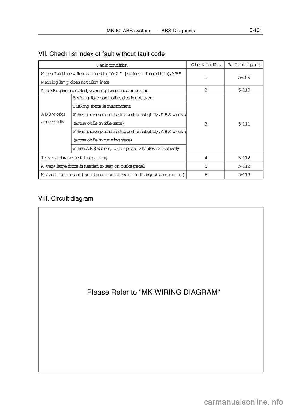
VIII. Circuit diagramVII. Check list index of fault without fault codeMK-60 ABS system -ABS Diagnosis5-101Fault condition
When Ignition switch is turned to "ON " (engine stall condition), ABS
warning lamp does not illuminate
After Engine is started, warning lamp does not go outCheck list No.
1
2
3
4
5
6Reference page
5-109
5-110
5-111
5-112
5-112
5-113 ABS works
abnormallyBraking force on both sides is not even
Braking force is insufficient
When brake pedal is stepped on slightly, ABS works
(automobile in idle state)
When brake pedal is stepped on slightly, ABS works
(automobile in running state)
When ABS works, brake pedal vibrates excessively
Travel of brake pedal is too long
A very large force is needed to step on brake pedal
No fault code output (cannot communicate with fault diagnosis instrument)Please Refer to "MK WIRING DIAGRAM"
Page 290 of 416

Abnormal
Replace HCUAbnormal
Replace HCUYes
Replace ABS ECUSection 2 ABS System CheckI. Check list of fault with fault codeNote: If storage battery is discharged excessively, it might fail to drive motor, so when conduct motor drive test,
firstly confirm whether voltage of storage battery is normal, when conduct motor drive test, vehicle must be in idle
state.MK-60 ABS system -ABS System Check5-103Fault code is 01276 1
[Description ] When vehicle speed exceeds 20 km/h, ABS ECU monitors that
motor can not work normally, it will record this fault code
[Prompt ] When this fault appears, wiring harness connection between motor
and ECU may get loose. Use hydraulic pressure unit functional
testing of fault diagnosis instrument to drive motor for this test.Possible cause
Power supply is discon-
nected or earthed
Motor wiring harness gets
loose
Motor is damaged
Pull out motor wiring harness plug, connect
battery power source directly to motor plug, see
whether motor works or not?
Check safety wire and ABS ECU joint
Connect motor wiring harness
Turn ignition switch to ON position
Eliminate fault code
Use fault diagnosis instrument to conduct
hydraulic control unit diagnosis
Whether fault recurs
Refer to "key points of occasional fault
repair"
Page 294 of 416
![GEELY MK 2008 Service Manual MK-60 ABS system -ABS System Check5-107Fault code is 01044 5
[Description]When ECU software code is inconsistent with hardware
bouncing pin connection, this fault code will appea GEELY MK 2008 Service Manual MK-60 ABS system -ABS System Check5-107Fault code is 01044 5
[Description]When ECU software code is inconsistent with hardware
bouncing pin connection, this fault code will appea](/img/58/57162/w960_57162-293.png)
MK-60 ABS system -ABS System Check5-107Fault code is 01044 5
[Description]When ECU software code is inconsistent with hardware
bouncing pin connection, this fault code will appearPossible cause
Bouncing pin connection
error in ABS wiring harness
Abs ecu coding error
Fault code is 00668 6
[Description]When supply terminal 30 does not supply voltage or
voltage is too high, this fault code will appear.Possible cause
Abs system fuse is blown out
Storage battery voltage is too
low or too high
ABS wiring harness socket
connector is damaged
ABS ECU is damaged
Check ABS system 30 A safety wireReplace fuse
NormalAbnormal
Disconnect connection of ABS wiring harness and ECU,
turn ignition switch to ON position, measure voltage value
between the following terminals of ABS wiring harness
Terminal 1 and 47 9.5 _ 16.5V
Terminal 32 and 16 9.5 - 16.5V
Terminal 4 and 16 9.5 _16.5VReplace fuse Normal
Check ABS wiring harness socket connectorReplace fuse Abnormal
Retry. Abnormity reoccursYes
Check storage battery voltageNormal Abnormal
NoRefer to repair of
occasional fault
Key pointsUse fault diagnosis instrument to check whether ABS ECU software
code is correct
Correct value: 040907Recode
YesNoCheck whether ABS wiring harness bouncing pin joint is connected
Bouncing pin joint : ABS ECU Pin 38and Pin 14Repair wiring harness Abnormal
Page 296 of 416

Check ABS warning lamp
safety wire in fuse boxCheck
ABS warning lamp safety wire
in fuse boxReplace AbnormalRemove ECU joint, when igni-
tion switch is in ON, does warn-
ing lamp illuminate ?NoNormalCheck whether ABS warn-
ing lamp is burnt outYes
ReplaceCheck whether warning
lamp power supply circuit
and ground loop in wiring
harness is disconnectedAbnormalRepair wiring
harnessCheck warning lamp power
supply circuit and ground
loop socket connector in
wiring harnessAbnormalRepair socket
connectorDoes fault reoccurNoRepair wiring harnessYe s NormalNormal NoRefer to key point
for repair of occa-
sional faultII. Check list of fault without malfunction codeMK-60 ABS system -ABS System Check5-109When ignition switch is in ON position (engine stall), ABS warning
lamp does not illuminate 1
[Description ] ABS warning lamp does not illuminate, warning lamp power
supply circuit might be disconnected, bulb is burnt out or
warning lamp driving module is damaged.Possible cause
Safety wire is burnt out
ABS warning lamp bulb
is burnt out
Power circuit is discon-
nected
ABS warning lamp driv-
ing module is damaged
YesCheck whether the wire in ABS
wiring harness connecting ABS
warning lamp driving module
and ECU is shorted to ground
Page 301 of 416

Inspection item
V
V
V
V
V
Visual inspection
Visual inspection
Visual inspection
Visual inspection
V
V
ohm
k ohm
MV/Hz
MV/Hz
MV/Hz
MV/Hz Storage battery voltage (motor)
Storage battery voltage
(Solenoid valve)
Power supply insulating property
Earth insulating property
Supply voltage
ABS warning lamp
Brake light switch function pedal
is not stepped down
Brake light switch function pedal
is stepped down
Diagnostic interface
Left front wheel speed sensor
resistance value
Right front wheel speed sensor
resistance value
Left rear wheel speed sensor
resistance value
Right rear wheel speed sensor
resistance value
Left front wheel sensor output
voltage value
Right front wheel sensor output
voltage value
Left rear wheel sensor output
voltage value
Right rear wheel sensor output
voltage value
Speed sensor output voltage ratio10.1 ~ 14.5
10.1 ~ 14.5
0.00 ~ 0.5
0.00 ~ 0.5
10.1 ~ 14.5
Warning lamp goes out
Warning lamp illuminates
Warning lamp goes out
Warning lamp illuminates
for about 1.7s,then goes out
0.0 ~ 0.5
10.0 ~ 14.5
0.0 ~ 0.5
1.2 ~ 1.3
1.2 ~ 1.3
1.0 ~ 1.3
1.0 ~ 1.3
3.4 ~ 14.8
3.4 ~ 14.8
>12.2
>12.2 1-47
32-16
4-16
16-47
4-16
ECU is not
connected
Connect ECU
16-41
16-41
Diagnosis joint
K and 7
45-46
33-34
37-36
42-43
45-46
33-34
37-36
42-43 OFF
OFF
OFF
OFF
ON
OFF
ON
OFF
ON
ON
ON
OFF
OFF
OFF
OFF
OFF
OFF
OFF
OFF
OFF
Maximum peak to peak value voltage
Minimum peak to peak value voltage2III. ABS system inspectionMK-60 ABS system -ABS System Check5-114Ignition switchpositionBinding post Standard value
Unitk ohmk ohmk ohm
Page 303 of 416
Section3 Removal and InstallationI. Precautions for removal and installation1. Firstly use diagnostic instrument to find out source of trouble, then repair.
2. Repair front prior use excluding mineral oil of detergent will surface clean Neatness ; repair when should note
before repair, use detergent without mineral oil to wipe off surface; pay attention to cleaning during repair, only
use rag without wool to wipe removed components.
3. Only use original factory spare parts, and new spare parts could only be unpacked just before installation.
4. Return liquid pump motor and hydraulic controller (HCU) is integrated structure, can not be separated.MK-60 ABS system -ABS System Check/ Removal and Installation5-116 d. Rotate the wheel at speed of about 1 / 2 turns per second, use multimeter or oscillograph to measure output
voltage
Terminal 45-46
Terminal 33-34
Terminal 37-36
Terminal 42-43
Output voltage
When use multimeter for measurement
See front wheel sensor drawing for front wheel.
See rear wheel sensor drawing for rear wheel
When use oscillograph for measurement
See relevant standard for front wheel.
See relevant standard for rear wheel.
e. If output voltage is not in above-mentioned range, the cause might be the following:
Air gap between sensor and pulse ring is too large.
Sensor fails.
Check sensor resistance value (1. 0 - 1. 3 k ohm).
Take four points on pulse ring to check air gap between pulse ring and wheel speed sensor (pulse ring
distortion).
2. Check hydraulic pressure unit HCU
a. Jack up vehicle to confirm that wheel may rotate freely.
b. Release manual brake.
c. After connecting fault diagnosis instrument, turn ignition switch to ON, here it is not necessary to start up
engine.
e. Check with reference to hydraulic control unit diagnosis.
Note: when connect or remove fault diagnosis instrument, ignition switch must be in OFF position
Page 304 of 416
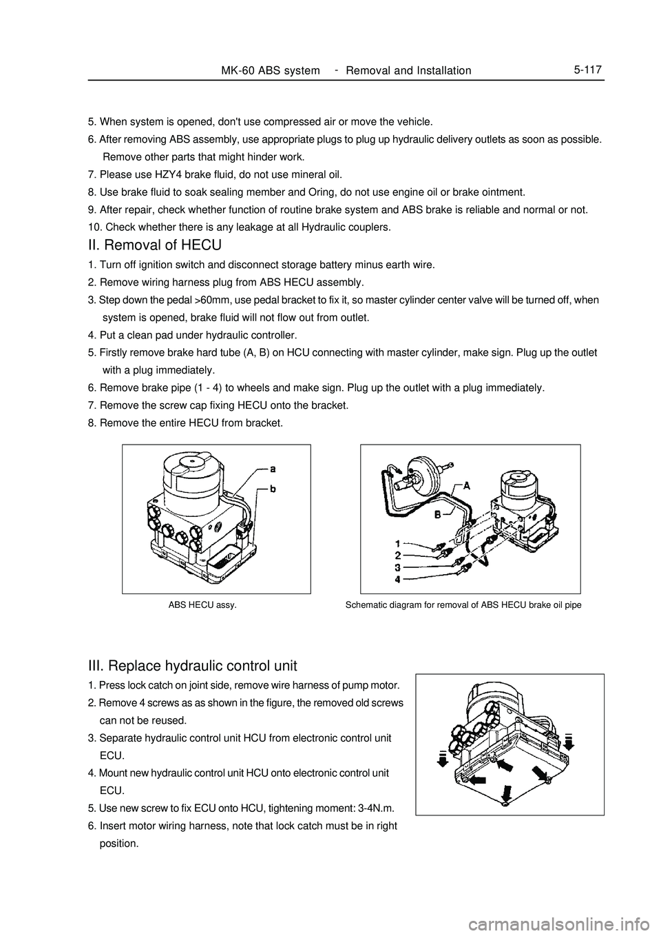
ABS HECU assy.III. Replace hydraulic control unit1. Press lock catch on joint side, remove wire harness of pump motor.
2. Remove 4 screws as as shown in the figure, the removed old screws
can not be reused.
3. Separate hydraulic control unit HCU from electronic control unit
ECU.
4. Mount new hydraulic control unit HCU onto electronic control unit
ECU.
5. Use new screw to fix ECU onto HCU, tightening moment: 3-4N.m.
6. Insert motor wiring harness, note that lock catch must be in right
position.MK-60 ABS system -
Removal and Installation5-117Schematic diagram for removal of ABS HECU brake oil pipe5. When system is opened, don't use compressed air or move the vehicle.
6. After removing ABS assembly, use appropriate plugs to plug up hydraulic delivery outlets as soon as possible.
Remove other parts that might hinder work.
7. Please use HZY4 brake fluid, do not use mineral oil.
8. Use brake fluid to soak sealing member and Oring, do not use engine oil or brake ointment.
9. After repair, check whether function of routine brake system and ABS brake is reliable and normal or not.
10. Check whether there is any leakage at all Hydraulic couplers.II. Removal of HECU1. Turn off ignition switch and disconnect storage battery minus earth wire.
2. Remove wiring harness plug from ABS HECU assembly.
3. Step down the pedal >60mm, use pedal bracket to fix it, so master cylinder center valve will be turned off, when
system is opened, brake fluid will not flow out from outlet.
4. Put a clean pad under hydraulic controller.
5. Firstly remove brake hard tube (A, B) on HCU connecting with master cylinder, make sign. Plug up the outlet
with a plug immediately.
6. Remove brake pipe (1 - 4) to wheels and make sign. Plug up the outlet with a plug immediately.
7. Remove the screw cap fixing HECU onto the bracket.
8. Remove the entire HECU from bracket.
Page 305 of 416
V. Reinstallation of ABS assemblyNote: plug of hydraulic opening on ABS assembly may be removed only when brake hard tube is to be installed,
so as to avoid foreign body entering brake system
1. Mount ABS assembly to bracket and tighten it, moment is 20~24 N.m.
2. Remove the plug on hydraulic opening, mount brake hard tube, confirm that hard tube connection is correct.
3. Mount brake hard tube to master cylinder.
4. Tightening moment for assembly of brake hard tube is 12~16N.m (M10 x 1) and 15~18 N.m (M12 x 1).
5. Fill new brake fluid into tank until liquid level reaches MAX place, use specified method to exhaust.
6. Turn ignition switch to ON, ABS warning lamp must illuminate for 1. 7s, then go out.
7. Eliminate fault code memory, reread to see whether there is any fault code.
8. Finally, run the vehicle in actual situation to confirm function of ABS (you should feel rebound of pedal).VI. ECU codeNote: when replacing HECU or ECU, encode new ECU, otherwise ABS warning lamp blinks, system can not work
normally.
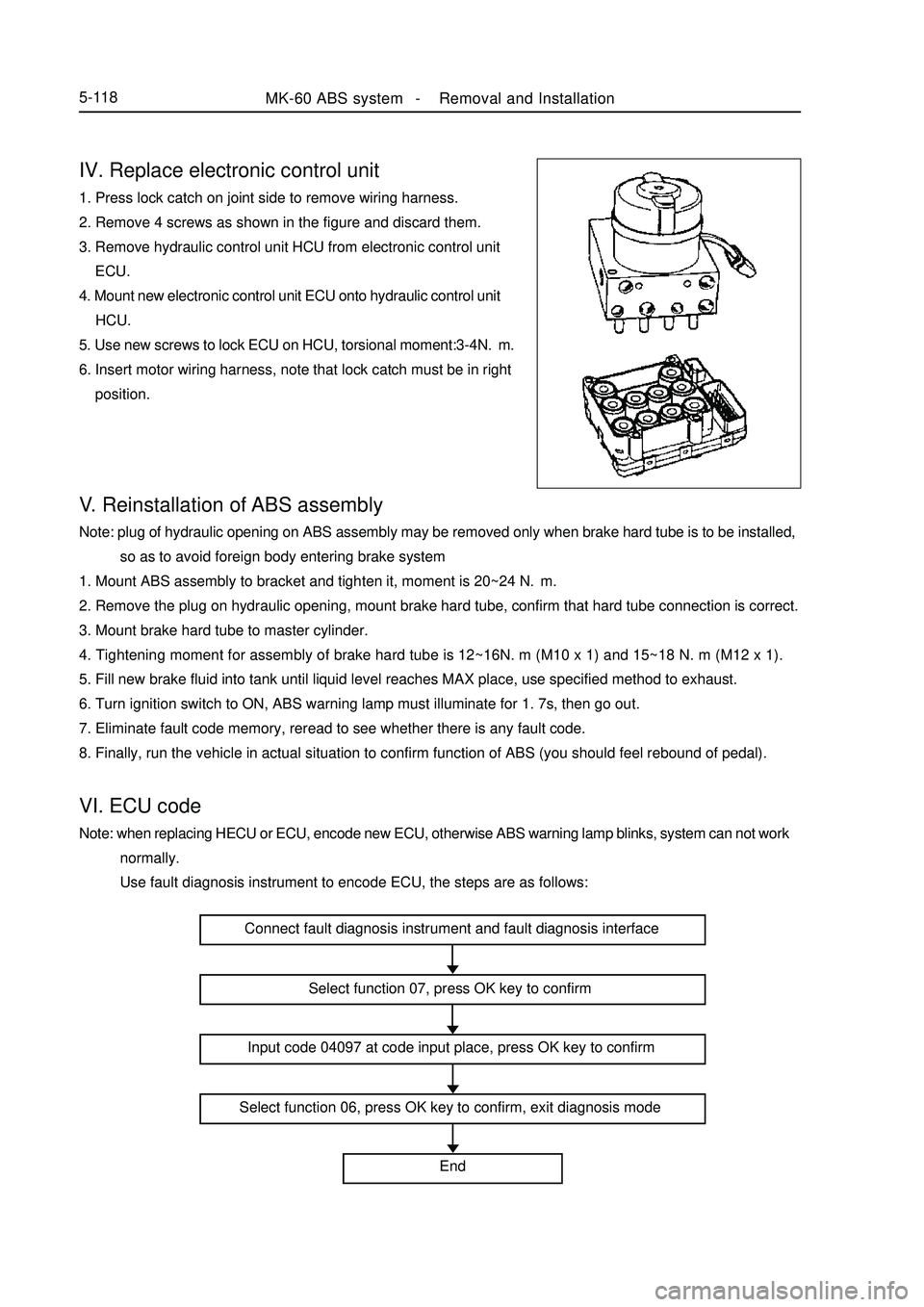
Use fault diagnosis instrument to encode ECU, the steps are as follows:IV. Replace electronic control unit1. Press lock catch on joint side to remove wiring harness.
2. Remove 4 screws as shown in the figure and discard them.
3. Remove hydraulic control unit HCU from electronic control unit
ECU.
4. Mount new electronic control unit ECU onto hydraulic control unit
HCU.
5. Use new screws to lock ECU on HCU, torsional moment:3-4N.m.
6. Insert motor wiring harness, note that lock catch must be in right
position.MK-60 ABS system -Removal and Installation5-118Connect fault diagnosis instrument and fault diagnosis interface
Select function 07, press OK key to confirm
Input code 04097 at code input place, press OK key to confirm
Select function 06, press OK key to confirm, exit diagnosis mode
End