clutch GREAT WALL HOVER 2006 Service Repair Manual
[x] Cancel search | Manufacturer: GREAT WALL, Model Year: 2006, Model line: HOVER, Model: GREAT WALL HOVER 2006Pages: 425, PDF Size: 26.05 MB
Page 9 of 425
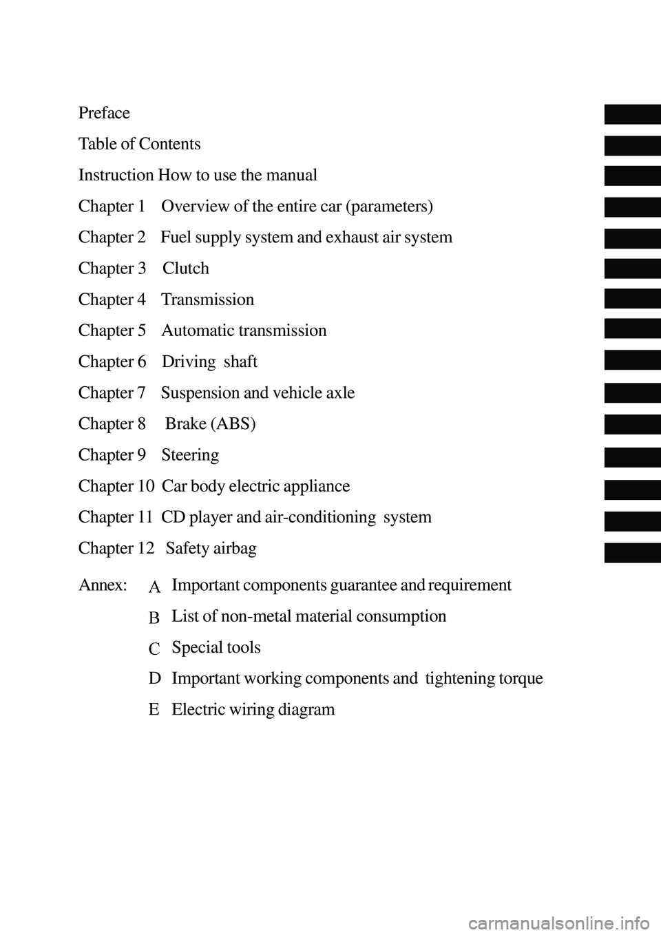
Preface
Table of Contents
Instruction How to use the manual
Chapter 1 Overview of the entire car (parameters)
Chapter 2 Fuel supply system and exhaust air system
Chapter 3 Clutch
Chapter 4 Transmission
Chapter 5 Automatic transmission
Chapter 6 Driving shaft
Chapter 7 Suspension and vehicle axle
Chapter 8 Brake (ABS)
Chapter 9 Steering
Chapter 10 Car body electric appliance
Chapter 11 CD player and air-conditioning system
Chapter 12 Safety airbag
Annex:
Important components guarantee and requirement
List of non-metal material consumption
Special tools
D Important working components and tightening torque
E Electric wiring diagram
Page 10 of 425
Overview of the entire car-1
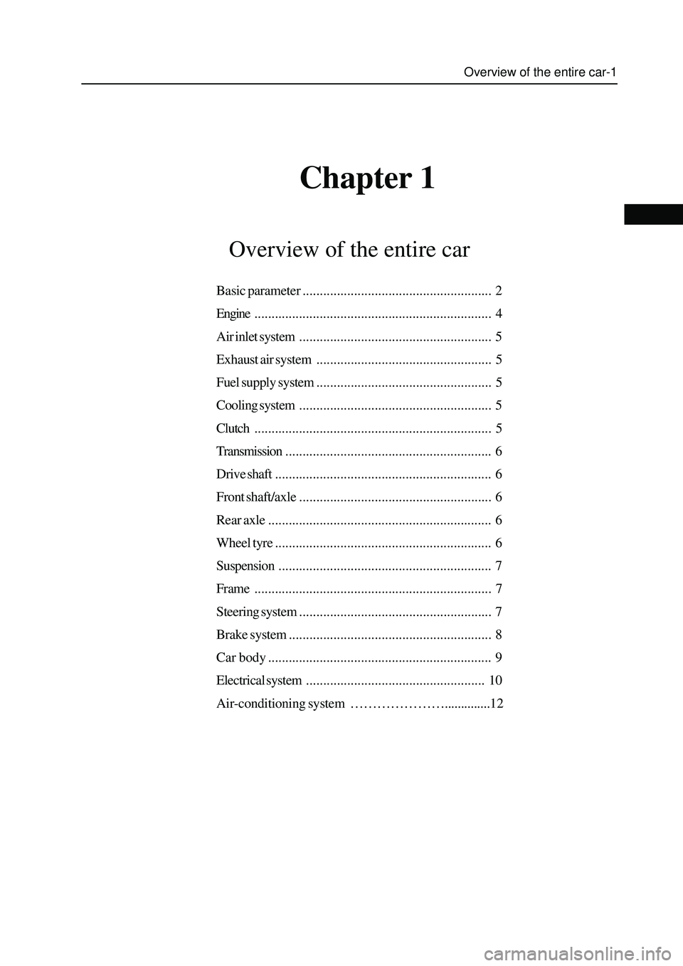
Chapter 1
Overview of the entire car
Basic parameter....................................................... 2
Engine..................................................................... 4
Air inlet system........................................................ 5
Exhaust air system................................................... 5
Fuel supply system................................................... 5
Cooling system........................................................ 5
Clutch..................................................................... 5
Transmission............................................................ 6
Drive shaft............................................................... 6
Front shaft/axle........................................................ 6
Rear axle................................................................. 6
Wheel tyre............................................................... 6
Suspension.............................................................. 7
Frame..................................................................... 7
Steering system........................................................ 7
Brake system........................................................... 8
Car body................................................................. 9
Electrical system.................................................... 10
Air-conditioning system …………………..............12
Page 14 of 425
Overview of the entire car-5
The friction, disc, single-diaphragm spring clutch, hydraulic control mechanism. The external diameter of friction disc D=225mm,
internal diameter d=150mm, material is F810.
Adjustment of clutch pedal:
1. Measure the height of clutch pedal (from pedal pad surface to floor) and free stroke of clutch pedal (fork bar pin clearance).
Standard height of clutch pedal: flush with the brake pedal, free stroke of clutch pedal is 5-15mm;
2. Readjust the free stroke of pedal after adjust the height of pedal; rotate the push bar to the standard value, then fix the bolt
and nut;
3. If the free stroke of clutch pedal is not within standard value, it should rotate the adjusting bolt to standard value, then fix
the bolt and nut. Do not move the push bar to main cylinder when adjust the free stroke of pedal;
4. If the free stroke of clutch pedal and clearance between the clutch pedal and floor when the clutch is disengaged de not
consist with the standard, this may by caused by the air in hydraulic system and failure of main cylinder or clutch. It can
discharge the air of system or dissemble and inspect the main cylinder or clutch.
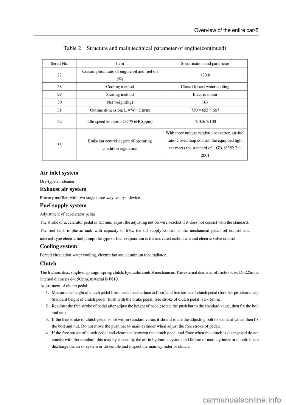
Table 2 Structure and main technical parameter of engine(continued)
Serial No. Item Specification and parameter
27 Consumption ratio of engine oil and fuel oil
(%) ≤0.8
28 Cooling method Closed forced water cooling
29 Starting method Electric motor
30 Net weight(kg) 167
31 Outline dimension: L×W×H (mm) 730×653×667
32 Idle-speed emission CO(%)/HC(ppm) ≤0.5/≤100
33 Emission control degree of operating
condition regulation With three unique catalytic converter, air-fuel
ratio closed loop control, the equipped light
car meets the standard of GB 18352.2-
2001
Air inlet system
Dry-type air cleaner.
Exhaust air system
Primary muffler, with two-stage three-way catalyst device.
Fuel supply system
Adjustment of accelerator pedal
The stroke of accelerator pedal is 155mm; adjust the adjusting nut on wire bracket if it does not consist with the standard.
The fuel tank is plastic tank with capacity of 67L; the oil supply control is the mechanical pedal oil control and
internal-type electric fuel pump; the type of fuel evaporation is the activated carbon can and electric valve control.
Cooling system
Forced circulation water cooling, electric fan and aluminum tube radiator.
Clutch
Page 31 of 425
Clutch-1
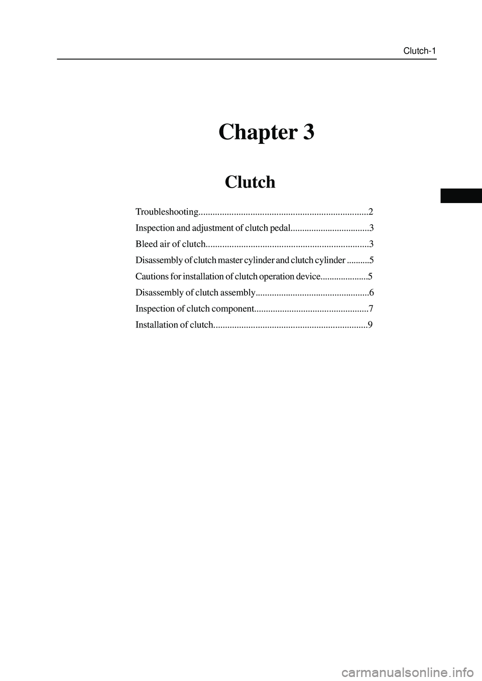
Chapter 3
Clutch
Troubleshooting........................................................................2
Inspection and adjustment of clutch pedal..................................3
Bleed air of clutch.....................................................................3
Disassembly of clutch master cylinder and clutch cylinder ..........5
Cautions for installation of clutch operation device.....................5
Disassembly of clutch assembly.................................................6
Inspection of clutch component.................................................7
Installation of clutch..................................................................9
Page 32 of 425
Clutch-2
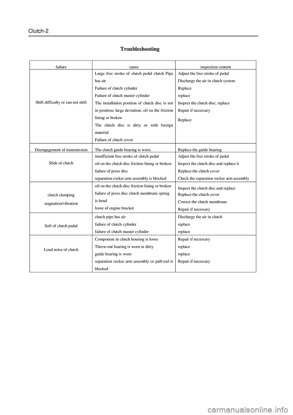
Troubleshooting
failure cause inspection content
Shift difficulty or can not shift
Large free stroke of clut ch pedal clutch Pipe
has air
Failure of clutch cylinder
Failure of clutch master cylinder
The installation position of clutch disc is not
in position; large deviation; oil on the friction
lining or broken
The clutch disc is dirty or with foreign
material
Failure of clutch cover Adjust the free stroke of pedal
Discharge the air in clutch system
Replace
replace
Inspect the clutch disc; replace
Repair if necessary
Replace
Disengagement of transmission The clutch guide bearing is worn. Replace the guide bearing
Slide of clut ch
insufficient free stroke of clutch pedal
oil on the clutch disc friction lining or broken
failure of press disc
separation rocker arm assembly is blocked Adjust the free stroke of pedal
Inspect the clutch disc and replace it
Replace the clut ch cover
Check the separation rocker arm assembly
clutch clamping
stagnation/vibration oil on the clutch disc friction lining or broken
failure of press disc clutch membrane spring
is bend
loose of engine bracket Inspect the clutch disc and replace
Replace the clut ch cover
Correct the clutch membrane
Repair if necessary
Soft of clutch pedal clutch pip e has air
failure of clutch cylinder
failure of clutch master cylinder Discharge the air in clutch
replace
replace
Loud noise of clut ch
Component in clutch housing is loose
Throw-out bearing is worn or dirty
guide bearing is worn
separation rocker arm assembly or pull-rod is
blocked Repair if necessary
replace
replace
Repair if necessary
Page 33 of 425
Clutch-3
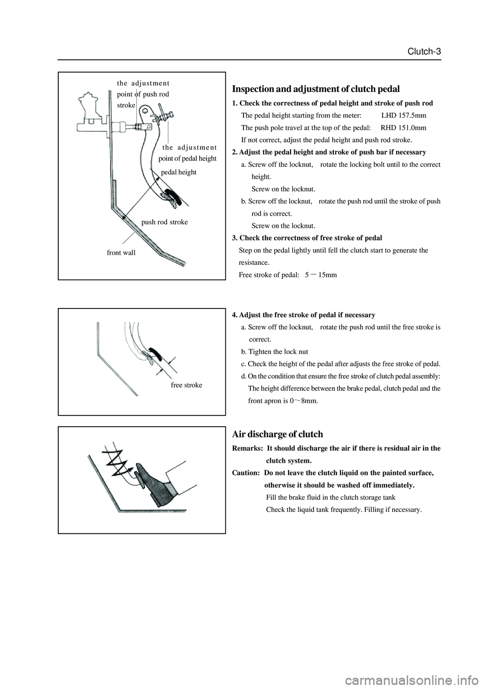
Inspection and adjustment of clutch pedal
1. Check the correctness of pedal height and stroke of push rod
The pedal height starting from the meter: LHD 157.5mm
The push pole travel at the top of the pedal: RHD 151.0mm
If not correct, adjust the pedal height and push rod stroke.
2. Adjust the pedal height and stroke of push bar if necessary
a. Screw off the locknut, rotate the locking bolt until to the correct
height.
Screw on the locknut.
b. Screw off the locknut, rotate the push rod until the stroke of push
rod is correct.
Screw on the locknut.
3. Check the correctness of free stroke of pedal
Step on the pedal lightly until fell the clutch start to generate the
resistance.
Free stroke of pedal: 5
15mm
4. Adjust the free stroke of pedal if necessary
a. Screw off the locknut, rotate the push rod until the free stroke is
correct.
b. Tighten the lock nut
c. Check the height of the pedal after adjusts the free stroke of pedal.
d. On the condition that ensure the free stroke of clutch pedal assembly:
The height difference between the brake pedal, clutch pedal and the
front apron is 0
8mm.
Air discharge of clutch
Remarks: It should discharge the air if there is residual air in the
clutch system.
Caution: Do not leave the clutch liquid on the painted surface,
otherwise it should be washed off immediately.
Fill the brake fluid in the clutch storage tank
Check the liquid tank frequently. Filling if necessary.
the adjustment
point of push rod
stroke
the adjustment
point of pedal height
pedal height
front wall
free stroke
push rod stroke
Page 34 of 425
Clutch-4
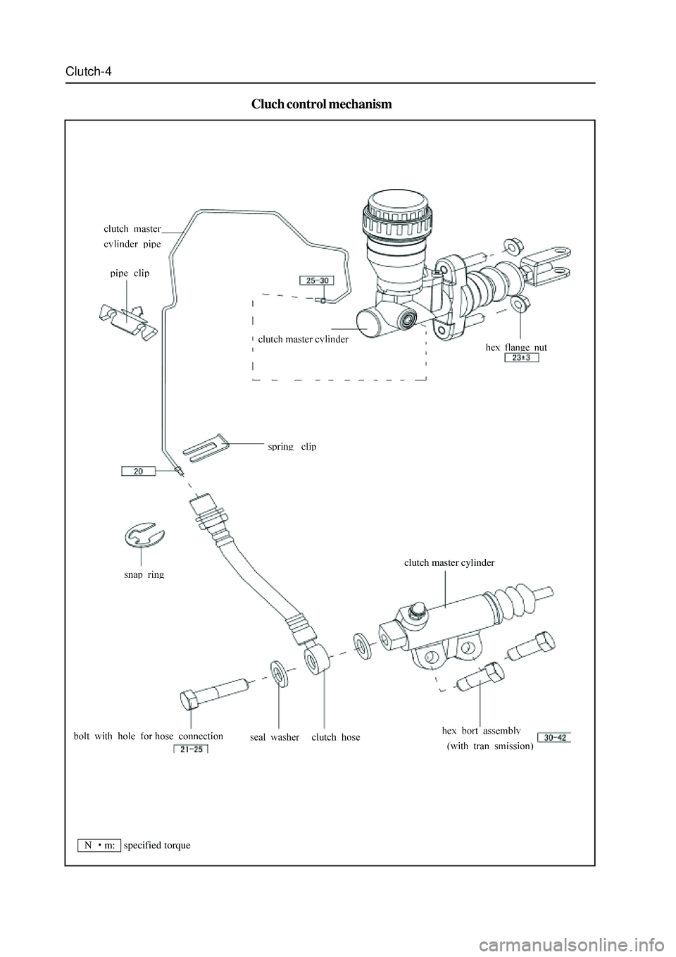
Cluch control mechanism
clutch master cylinder
N
m: specified torque
Page 35 of 425
Clutch-5
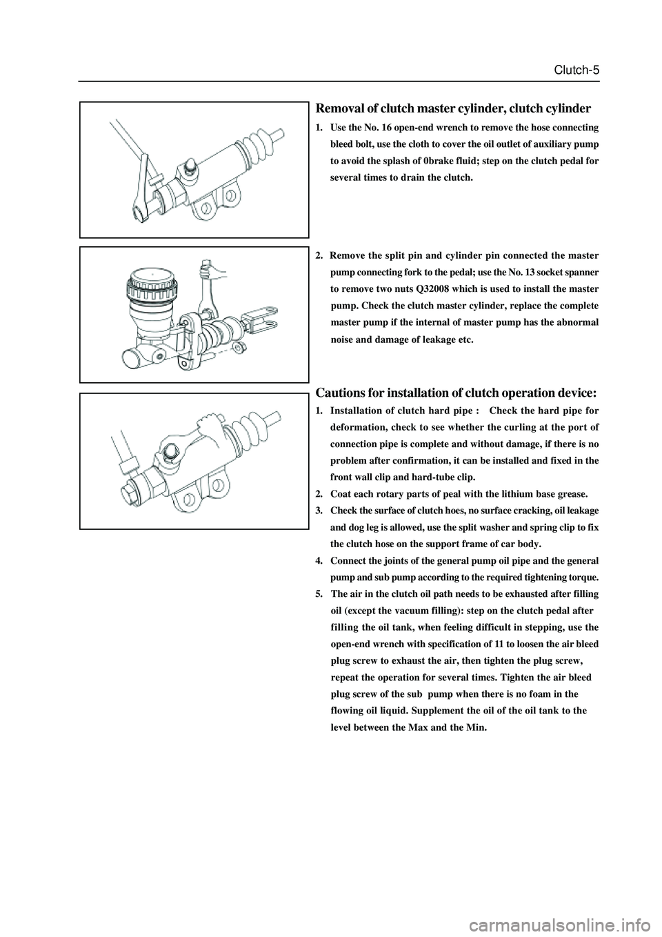
Removal of clutch master cylinder, clutch cylinder
1. Use the No. 16 open-end wrench to remove the hose connecting
bleed bolt, use the cloth to cover the oil outlet of auxiliary pump
to avoid the splash of 0brake fluid; step on the clutch pedal for
several times to drain the clutch.
Cautions for installation of clutch operation device:
1. Installation of clutch hard pipe : Check the hard pipe for
deformation, check to see whether the curling at the port of
connection pipe is complete and without damage, if there is no
problem after confirmation, it can be installed and fixed in the
front wall clip and hard-tube clip.
2. Coat each rotary parts of peal with the lithium base grease.
3. Check the surface of clutch hoes, no surface cracking, oil leakage
and dog leg is allowed, use the split washer and spring clip to fix
the clutch hose on the support frame of car body.
4. Connect the joints of the general pump oil pipe and the general
2. Remove the split pin and cylinder pin connected the master
pump connecting fork to the pedal; use the No. 13 socket spanner
to remove two nuts Q32008 which is used to install the master
pump. Check the clutch master cylinder, replace the complete
master pump if the internal of master pump has the abnormal
noise and damage of leakage etc.
pump and sub pump according to the required tightening torque.
5. The air in the clutch oil path needs to be exhausted after filling
oil (except the vacuum filling): step on the clutch pedal after
fillingthe oil tank, when feeling difficult in stepping, use the
open-end wrench with specification of 11 to loosen the air bleed
plug screw to exhaust the air, then tighten the plug screw,
repeat the operation for several times. Tighten the air bleed
plug screw of the sub pump when there is no foam in the
flowing oil liquid. Supplement the oil of the oil tank to the
level between the Max and the Min.
Page 36 of 425
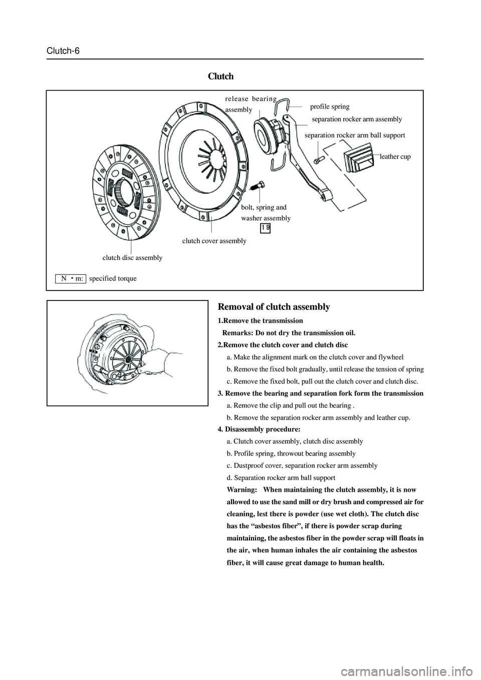
Clutch-6
Clutch
4. Disassembly procedure:
a. Clutch cover assembly, clutch disc assembly
b. Profile spring, throwout bearing assembly
c. Dustproof cover, separation rocker arm assembly
d. Separation rocker arm ball support
Warning: When maintaining the clutch assembly, it is now
allowed to use the sand mill or dry brush and compressed air for
cleaning, lest there is powder (use wet cloth). The clutch disc
has the “asbestos fiber”, if there is powder scrap during
maintaining, the asbestos fiber in the powder scrap will floats in
the air, when human inhales the air containing the asbestos
fiber, it will cause great damage to human health.
Removal of clutch assembly
1.Remove the transmission
Remarks: Do not dry the transmission oil.
2.Remove the clutch cover and clutch disc
a. Make the alignment mark on the clutch cover and flywheel
b. Remove the fixed bolt gradually, until release the tension of spring
c. Remove the fixed bolt, pull out the clutch cover and clutch disc.
3. Remove the bearing and separation fork form the transmission
a. Remove the clip and pull out the bearing .
b. Remove the separation rocker arm assembly and leather cup.
clutch disc assembly
clutch cover assembly
bolt, spring and
washer assembly release bearing
assembly
profile spring
separation rocker arm assembly
separation rocker arm ball support
leather cup
N m: specified torque
Page 37 of 425
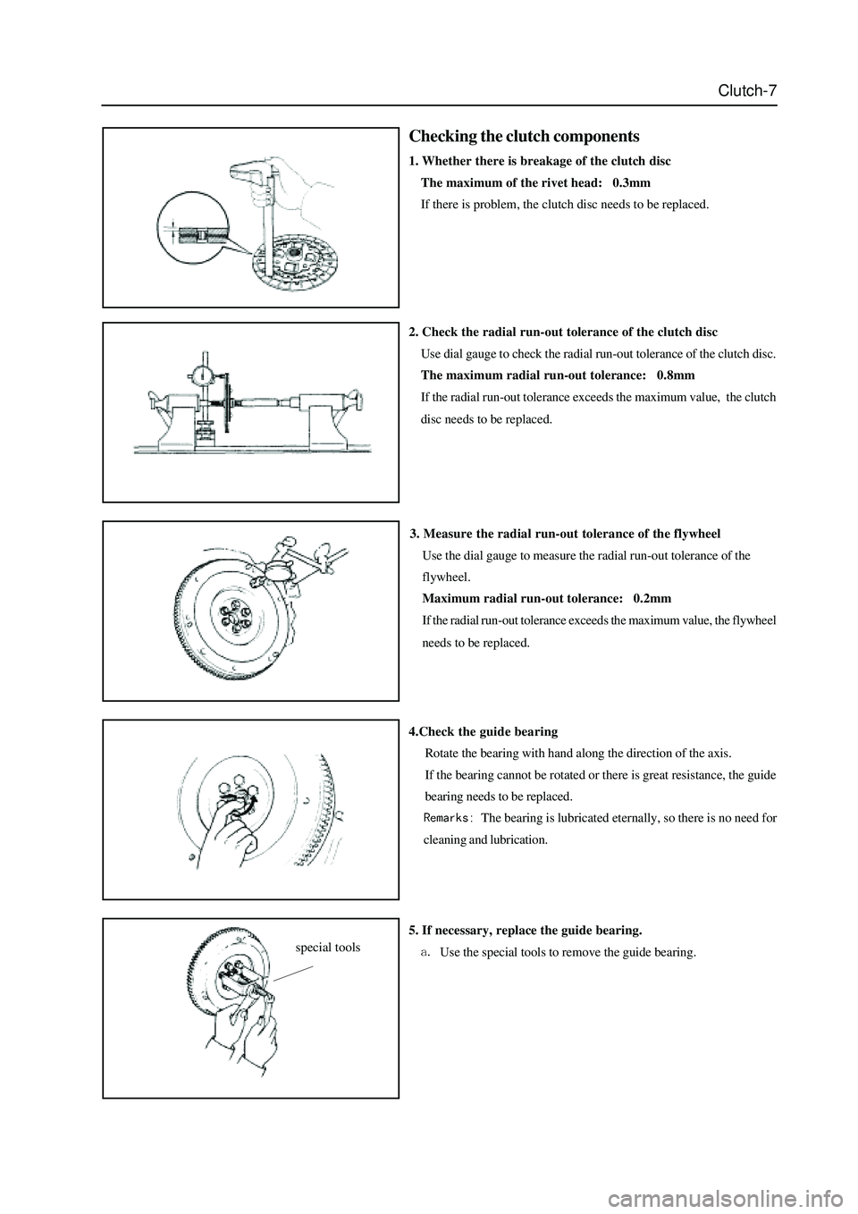
Clutch-7
Checking the clutch components
1. Whether there is breakage of the clutch disc
The maximum of the rivet head: 0.3mm
If there is problem, the clutch disc needs to be replaced.
3. Measure the radial run-out tolerance of the flywheel
Use the dial gauge to measure the radial run-out tolerance of the
flywheel.
Maximum radial run-out tolerance: 0.2mm
If the radial run-out tolerance exceeds the maximum value, the flywheel
needs to be replaced.
4.Check the guide bearing
Rotate the bearing with hand along the direction of the axis.
If the bearing cannot be rotated or there is great resistance, the guide
bearing needs to be replaced.
The bearing is lubricated eternally, so there is no need for
cleaning and lubrication. 2. Check the radial run-out tolerance of the clutch disc
Use dial gauge to check the radial run-out tolerance of the clutch disc.
The maximum radial run-out tolerance: 0.8mm
If the radial run-out tolerance exceeds the maximum value, the clutch
disc needs to be replaced.
5. If necessary, replace the guide bearing.
Use the special tools to remove the guide bearing.special tools