100 HONDA CIVIC 2000 6.G Workshop Manual
[x] Cancel search | Manufacturer: HONDA, Model Year: 2000, Model line: CIVIC, Model: HONDA CIVIC 2000 6.GPages: 2189, PDF Size: 69.39 MB
Page 1007 of 2189

Differential
Bearing Replacement
NOTE: Check the bearings for wear and rough rotation.
lf the bearings are OK, removal is not necessary.
'1. Remove the ball bearings using a bearing puller.
Install the new ball bearings
with a press as shown.
BAI-L BEARING
using the special tool
ORIVER 10 mm l.O.
07746 - 0030100
14-330
BALL BEARING
Differential Carrier Replacement
1. Remove the final driven gear from the differential
carner.
NOTE: The final driven gear bolts have left-hand
threads.
BOLTS10 x 1,0 mm98 N'm 110,0 kgf.m,72 tbl.ttlLeft-hand threads
DIFFERENTIALCARRIER
Install the final driven gear with its chamfered side
on the inner bore facing the differential carrier.
Tighten the bolts to the specified torque in a crisscross
Paftern.
TOROUE: 98 N.m (10.0 kgt.m, 72 lbf.ft)
Page 1012 of 2189
Flywheel Housing
Bearing
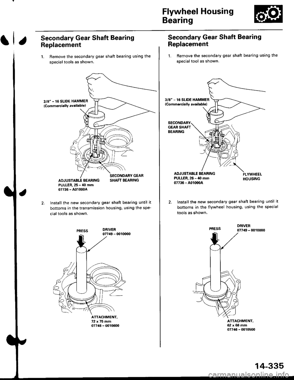
Secondary Gear Shaft Bearing
Replacement
1. Remove the secondary gear shaft bearing using the
special tools as shown.
3/8" - 16 SLIDE HAMMER
{Comm6rciallY availablel
SECONDARY GEAR
ADJUSTABI.T BEARING SHAFT BEARINGPULLER.25 - 40 mm07736 - A01000A
Install the new secondary gear shaft bearing until it
bottoms in the transmission housing. using the spe-
cial tools as shown.
Secondary Gear Shaft Bearing
Replacement
1. Remove the secondary gear shaft bearing using the
soecial tool as shown.
3/8" - 16 SLIDE HAMMER
lCommorcially aY.ilabl6l
2. lnstall the new secondary gear shaft bearing until it
bottoms in the flywheel housing, using the special
tools as shown.
DRIVER07749 - (x)10000
ATTACHMENT.62xGgmm07745 - 0010500
14-335
Page 1035 of 2189
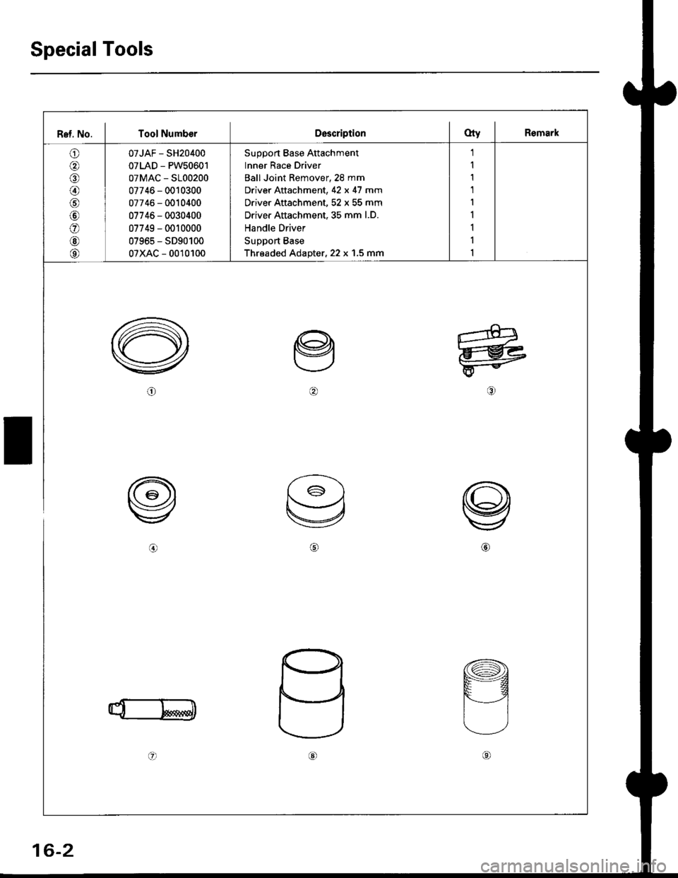
Special Tools
Ref. No. I Tool NumberDescriptionOty I Remark
o
@,a
\9'
o
@
@
07JAF - SH20400
07LAD - PW50601
07MAC - S100200
07746 - 0010300
07746 - 0010400
07746 - 0030400
07749 - 0010000
07965 - SD90100
07xAc - 0010100
Support Base Attachment
Inner Race Driver
Ball Joint Remover, 28 mm
Driver Attachment, 42 x 47 mm
Driver Attachment, 52 x 55 mm
Driver Attachment, 35 mm l.D.
Handle Driver
Support Base
Threaded Adapter, 22 x 1.5 mm
1
1
1
1
I
I
1
I
1
@e
@
&
w
@
@
c
6
@
'
lo,
c[G)
8-)
ge
l..---,l
G)
16-2
Page 1048 of 2189
J)
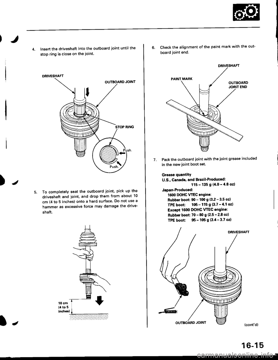
4. lnsert the driveshaft into the outboard joint until the
stop ring is close on the ioint.
DRIVESHAFT
To completely seat the outboard joint, pick up the
driveshaft and joint, and drop them from about 10
cm (4 to 5 inches) onto a hard surface. Do not use a
hammer as excessive force may damage the drive-
shaft.
16-15
J
6. Check the alignment of the paint mark with the out-
board joint end.
Pack the outboard joint with the joint grease includsd
in th€ new ioint boot set.
Gleaso quanlity
U.S., canada, and Brazil'Ploducod:
115 - 135 g {4.0 - 4.8 oz}
Japan-Producod:
161X, DOHC VTEC angino:
Rubbor boot: 90 - 100 g 13.2 - 3.5 oz)
TPE boot: 1tl6 - 115 I {3'7 - tl'l oz}
Excapt 1000 DOHC VTEC engine:
Rubbel boot: 70 - 80 g l.2.5 - 2.8 ozl
TPE boot: 95 - 105 g {3.4- 3.7 oz}
7.
DRIVESHAFT
(cont'd)
Page 1054 of 2189
Disassembly
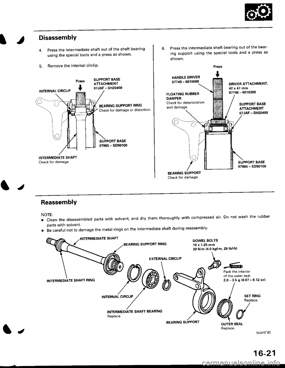
Press the intermediate shaft out of the shaft bearing
using the special tools and a press as shown.
Remove the internal circliP
Press
I
SUPPORT BASEATTACHMENT07JAF - SH20400INTERNAL CIBCLIP
BEARING SUPPORT RING
Check for damage or distortion
6. Press the intermediate shaft bearing out ot the bear-
ing support using the special tools and a press as
shown.
HANOLE DRIVER
0?749 - 00'10000
Press
I
DRIVER ATTACHMENT,12x47 mm07746 - 0010300FLOATING RUBBEB
DAMPERCheck for deterioration
and oamage.SUPPORT BASE
ATTACHMENT07JAF _ SH20it00
BEARING SUPPORT
Check for damage
I sErR'NG
A4 Reolace
VUOUTER SEALReplace.(cont'd)
ReassemblY
NOTE:
. clean the disassembted parts with solvent, and dry them thoroughly with compressed air' Do not wash the rubber
parts with solvent.
. Becareful not to da mage the metal ringson the intermediate shaftduring reassembly'
BEARING SUPPORT RINGDOWEL BOLTS10 x 1.25 mm39 N.m 14.0 kgf.m,29 lbIftl
EXTERNAL CIRCLIP
Pack the interiorof the outer seal.2.0-35s10.07-012oz)
INTERNAL CIRCLIP
INTERMEDTATE SHAFT BEARING
Replace,
INTERMEDIATE SHAFT RING
lJ
16-21
Page 1058 of 2189
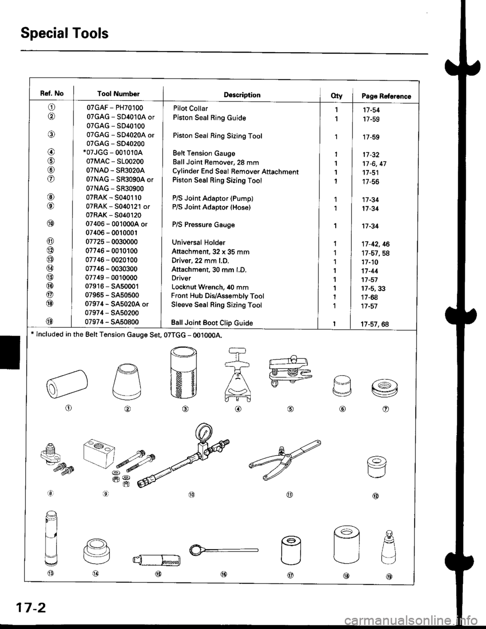
Ref. No I Tool NumberDescriptionOty I Pag€ Reterence
o
@
@
@
@
fof
@
@
@
@
@
@
@
@
@
@
@
@
@
07GAF - PH70100
07GAG - SD4010A or
07GAG - SD40100
07GAG - SD4020A or
07GAG - S040200*07JGG - 00r 010A
07MAC - 5100200
OTNAD - SR3O2OA
07NAG - SR3090A or
07NAG - SR30900
07RAK - 5040110
07RAK - 5040121 or
07RAK - 5040t20
07406 - 0010004 or
07406 - 001000r
07725 - 0030000
07746 - 0010100
07746 - 0020100
07746 - 0030300
07749 - 0010000
07916 - SA50001
07965 - SA50500
07974 - SA5020A or
07974 - SA50200
07974 - SA50800
Pilot Collar
Piston Seal Ring Guide
Piston Seal Ring Sizing Tool
Belt Tension Gauge
Ball Joint Remover, 28 mm
Cylinder End Seal Bemover Attachment
Piston Seal Ring Sizing Tool
P/S Joint Adaptor (Pump)
P/S Joint Adaptor (Hose)
P/S Pressure Gauge
Universal Holder
Attachment,32 x 35 mm
Driver, 22 mm l.D.
Attachment, 30 mm l.D.
Driver
Locknut Wrench, 40 mm
Front Hub DiVAssembly Tool
Sleeve Seal Ring Sizing Tool
Bsll Joint Boot Clip Guide
1
1
'I
1'I
1
I
1
1
I
1
1
I
1
1
I
1
I
11-54
17-59
'17-59
17 -32
17 -6, 47
17-51
| /-ao
17 -34
17 -31
't7 -34
't7-42, 16
17-57,58
17-10
17-44't7 -57
17-5,33
17-68
17 -57
17-57, 6A* lncluded in the Belt Tension cauge Set, 07TGG - OO10OOA.
o
p
v
@o
€_
ts7-dysB
aal
@@
(o)
F=1
@@@
@@@
17-2
Page 1066 of 2189
Steering Gearbox
Reassembly (cont'dl
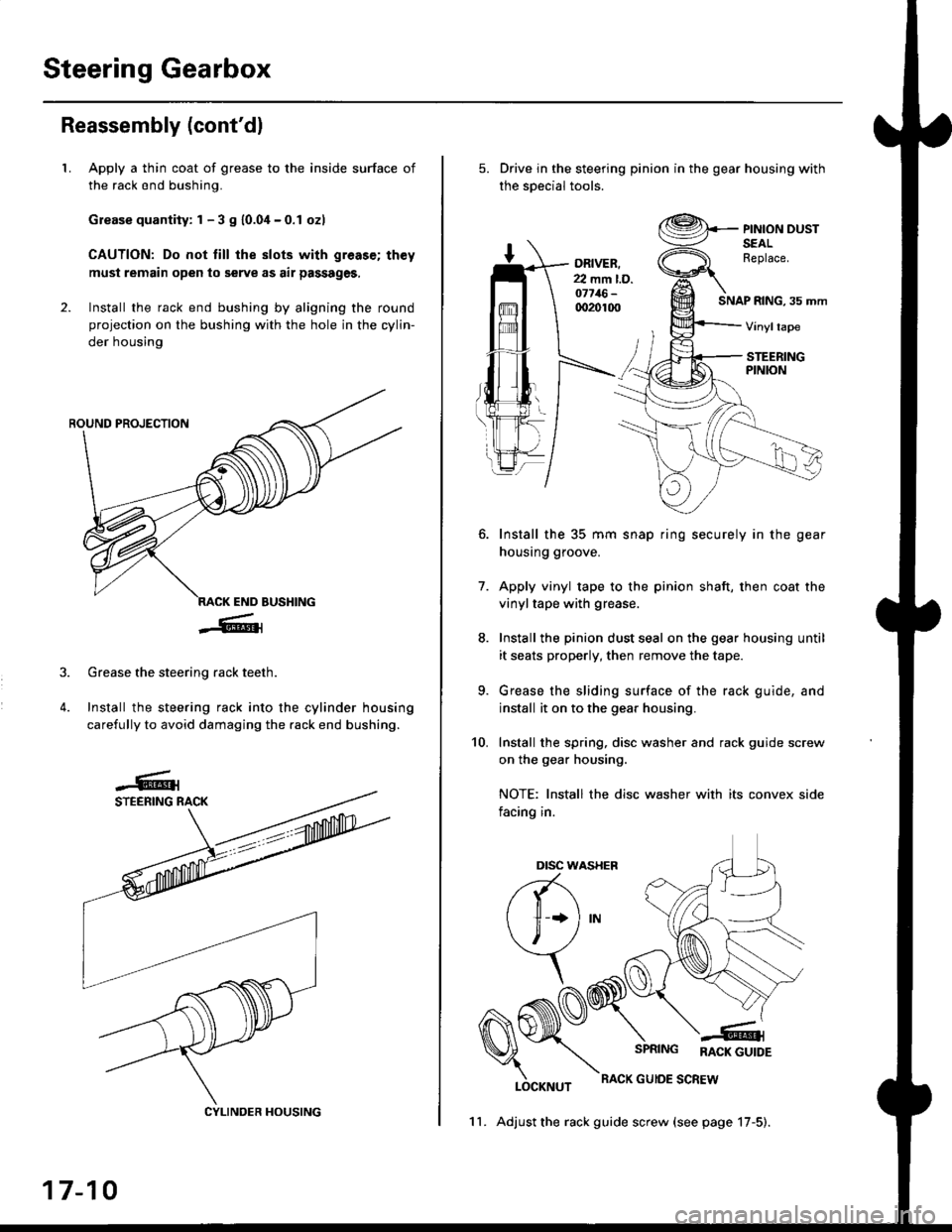
LApply a thin coat of grease to the inside surface of
the rack end bushing.
Grease quantity: 1 - 3 S 10.04-0.1 ozl
CAUTION: Do not till the slots with greas€; th€y
must remain open to serve as air passages,
Install the rack end bushing by aligning the round
projection on the bushing with the hole in the cylin-
der housing
4.
Grease the steering rack teeth.
Install the steering rack into the cylinder housing
carefully to avoid damaging the rack end bushing.
CYLINDER HOUSING
17-10
11. Adjust the rack guide screw (see page 17-5).
Drive in the steering pinion in the gear housing with
the soecial tools.
ORIVER.22 mm l.D.o7716-qr20100SNAP RING, 35 mm
PINION DUSTSEALReplace.
Vinyltape
STEERINGPINION
7.
Install the 35 mm snap ring securely in the gear
housing groove.
Apply vinyl tape to the pinion shaft, then coat the
vinyltape with grease.
Install the pinion dust seal on the gear housing until
it seats properly, then remove the tape.
Grease the sliding surface of the rack guide, and
install it on to the gear housing.
Install the spring, disc washer and rack guide screw
on the gear housing.
NOTE: Install the disc washer with its convex side
facing in.
LOCKNUT
SPRING RACK GUTDE
RACK GUIOE SCREW
10.
Dtsc w,
a(-\
l1 *l
\, ,/
\
Page 1090 of 2189
lnspection and Adjustment
Pump Pressure Check
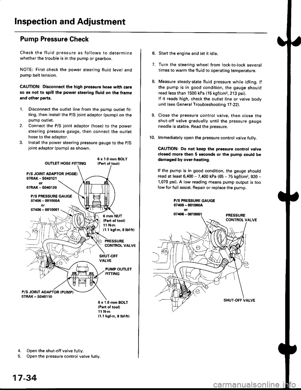
Check the fluid pressure as follows to determine
whether the trouble is in the pump or gearbox.
NOTE: First check the power steering fluid level andpump belt tension.
CAUTION: Disconnect the high pr$sure hos€ with care
so as not lo spill the power sieering tluid on tha frame
and other parts.
1. Disconnect the outlet line from the Dumo outlet fit-
ting, then installthe P/S joint adaptor (pump) on the
Dumo outlet.
2. Connect the P/S joint adaptor (hose) to the power
steering pressure gauge, then connect the outlet
hose to the adaptor.
3. Install the power steering pressure gauge to the P/Sjoint adaptor (pump) as shown.
ourlEr HosE FnrNo ,t"ll lrilu"ott
P/S JOINT ADAPTOB IHOSEI07RAK - S0i10l2rol07RAK- 50{{)120
P/S PRESSURE GAUGE07406 - 001000Aor07406 - 0010001
4. Open the shut-off valve fully.
5. Open the pressure control valve fully.
17-34
(Pa.t of tooll11 N.m11.1 kgt m, 8 lbf.ftl
PRESSURECONTROL VALVE
SHUT.OFFVALVE
PUMP OUTLETFITTING
6 x 1.0 mm BOLTlPart of tool)11 N.m11.1 kgf m, 8 lbtftl
7.
Start the engine and let it idle.
Turn the steering wheel from lock-to-lock several
times to warm the fluid to operating temperature.
Measure steady-state fluid pressure while idling. If
the pump is in good condition, the gauge should
read less than 1500 kPa (15 kgf/cmr, 213 psi).
lf it reads high, check the outlet line or valve body
unit (see General Troubleshooting 17-22).
Close the pressure control valve, then close the
shut-off valve gradually until the pressure gauge
needle is stable. Read the oressure.
lmmediately open the pressure control valve fully.
GAUTION: Do not keep lhe prossure control valve
clos€d more then 5 soconds or the pump could be
damagod by over-heating.
lf the pump is in good condition, the gauge should
read at least 6,400 - 7,400 kPa (65 - 75 kgflcm,, 920 -
1,070 psi). A low reading means pump output is too
low for full assist. Repair or replace the pump,
9.
P/S PBESSURE GAUGE07{16 -@1@OA
oi
SI{UT.OFF VALVE
Page 1110 of 2189
Steering Gearbox
Disassembly (cont'd)
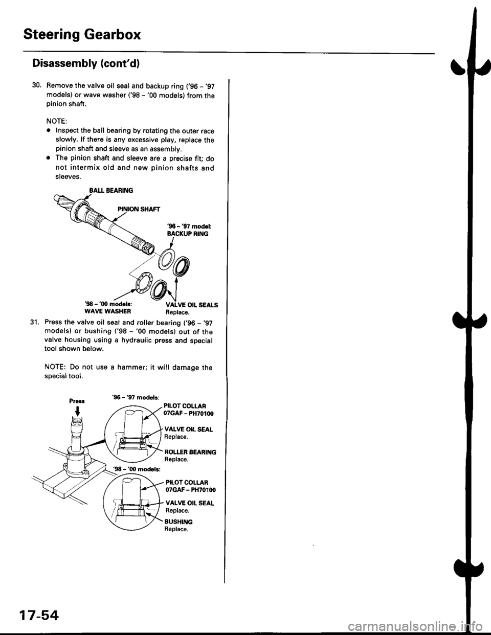
30. Bemove the valve oil seal and backup ring {'96 -'97
models) or wave washer ('98 -'00 models) from theoinion shaft.
NOTE:
. Inspect the ball bearing by rotating the outer race
slowly. lf there is any excessive play, replace thepinion shaft and sleeve as an assembly.
. The pinion shaft and sleeve are a precise fit; do
not intermix old and new pinion shafts and
steeves.
'98 - '(x) mod.lr:WAVE WASHERReplace.
31.Press the valve oil seal and roller bearing {'96 -,97
modelsl or bushing ('98 -'00 modelsl out of thevalve housing using a hydraulic press and specialtool shown below.
NOTE: Do not use a hammer; it will damage the
specialtool.
'96 - '97 modob:
PILOT COLLAR07GAF - PH70100
VAI.VE OIL SEALReplace.
BOI.I"ER BEARINGReplace.
PILOT COLLAR07GAF - PHtoroo
VALVE OII. SEALReplace.
BUSHINGBeplace.
BALL BEARING
'96 - '00 mod.b:
17-54
Page 1113 of 2189
I
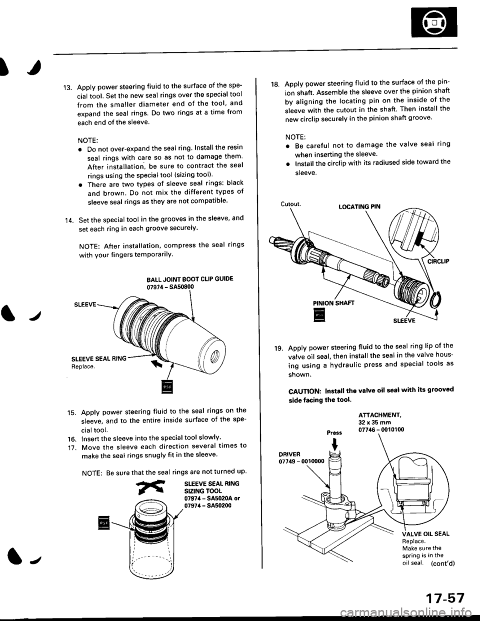
14.
Apply power steering fluid to the surface of the spe-
cial tool. Set the new seal rings over the special tool
from the smaller diameter end of the tool, and
expand the seal rings. Do two rings at a time from
each end of the sleeve.
NOTE;
. Do not over-expand the seal ring. Installthe resin
seal rings with care so as not to damage them'
After installation, be sure to contract the seal
rings using the specialtool (sizing tool).
. There are two types of sleeve seal rings: black
and brown. Do not mix the different types of
sleeve seal rings as they are not compatible
Set the special tool in the grooves in the sleeve, and
set each ring in each groove securely.
NOTE: After installation, compress the seal rings
with your fingers temPorarilY
BALL JOINT BOOI CLIP GUIDE
07S7,1- SA50800
SLEEVE
15. Apply power steering fluid to the seal rings on the
sleeve, and to the entire inside surface of the spe-
cial tool.
16. lnsert the sleeve into the specialtool slowly'
17. Move the sleeve each direction several times to
make the seal rings snugly fit in the sleeve'
NOTE: Be surerings are not turned uP.
SITEVE SEAL RINGSIZING TOOL0797a - SA5020A or07974 - SA50200
that the seal
fr
J
17-57
18. Apply power steering fluid to the surface o{ the pin-
ion shaft. Assemble the sleeve over the pinion shaft
by aligning the locating pin on the inside of the
sleeve with the cutout in the shaft. Then install the
new circlip securely in the pinion shaft groove'
NOTE:
Be careful not to damage the valve seal ring
when inserting the sleeve.
Installthe circlip with its radiused side toward the
sleeve.
Apply power steering fluid to the seal ring lip of the
valve oil seal. then install the seal in the valve hous-
ing using a hydraulic press and special tools as
shown.
CAUTION: Install the valve oil seal with its grooved
side facing the tool.
'19.
ATTACHMENT.32x35mm0774.6 - q)101(x)Pre3s
IDRIVER07749 - 0010000
VALVE OIL SEALReplace.Make sure thespring is in the
oil seal. (cont'd)