lock HONDA CIVIC 2002 7.G User Guide
[x] Cancel search | Manufacturer: HONDA, Model Year: 2002, Model line: CIVIC, Model: HONDA CIVIC 2002 7.GPages: 1139, PDF Size: 28.19 MB
Page 44 of 1139
Starter Replacement
1. Make sure you have the anti-theft code for the radio.
then write down the frequencies for the radio's
preset buttons.
2. Disconnect the negative cable from the battery first,
then disconnect the positive cable.
3. Disconnect the knock sensor connector.
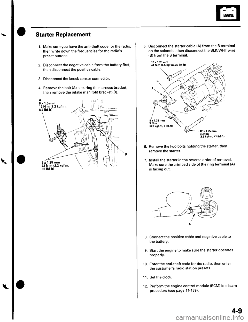
4. Remove the bolt (A) securing the harness bracket,
then remove the intake manifold bracket (B).
A6x1,0mm12 N.m {1.2 kgf.m,8.7 tbt.ft)
8 x 1.25 mm22 N,m 12.2 kgt.m,16 rbf.ftl
L't2.
4-9
5. Disconnect the starter cable (A)from the B terminal
on the solenoid, then disconnect the BLK,/WHT wire
{B) from the S terminal.
10 x 1.25 mm44 N.m {a.5 kgf.m,33lblft)
8 x 1.25 mm9Nm10.9 kgf.m,7 lbl ft)
7.
9.
'10.
11.
2
S'-12x12smm6ilNm{6.5 kgl m,47lbfft)
Remove the two bolts holding the starter, then
remove the starter.
lnstall the starter in the reverse order of removal.
Make sure the crimped side of the ring terminal (A)
is facing out.
Connect the positive cable and negative cable to
the batterY.
Start the engine to make sure the starter operates
propeny.
Enter the anti-theft code for the radio, then enter
the customer's radio station presets.
Set the clock.
Perform the engine control module (EcM) idle learn
procedure (see page 1 '1- 139 ).
I
Page 49 of 1139
Starting System
Starter Overhaul (cont'dl
Planetary Gear Inspection
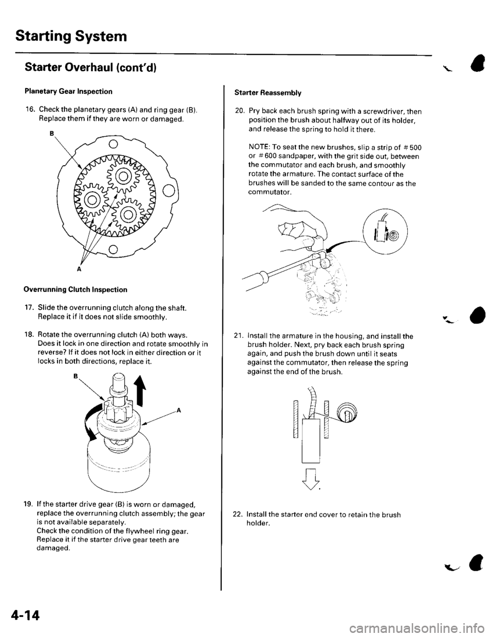
16. Check the planetary gears (A) and ring gear {B).Replace them if they are worn or damaged.
Overrunning Cluich Inspection
17. Slide the overrunning clutch along the shaft.
Replace it if it does not slide smoothly.
18. Rotate the overrunning clutch (A) both ways.
Does it lock in one direction and rotate smoothly inreverse? lf it does not lock in either direction or it
locks in both directions, replace it.
lf the starter drive gear (B) is worn or damaged,
replace the overrunning clutch assembly; the gear
is not available separately.
Check the condition of the flywheel ring gear.
Replace it if the starter drive gear teeth are
oamageo.
19.
4-14
i.-
Starter Reassembly
20, Pry back each brush spring with a screwdriver, thenposition the brush about halfway out of its holder,
and release the spring to hold it there.
NOTE: To seatthe new brushes. slip a strip of #5OO
or # 600 sandpaper. with the grit side out, be&veen
the commutator and each brush, and smoothly
rotate the armature. The contact surface of the
brushes will be sanded to the same contour as the
commutator.
21lnstallthe armature in the housing, and installthe
brush holder. Next, pry back each brush spring
again, and push the brush down until it seats
against the commutator, then release the spring
against the end of the brush.
s
Install the starter end cover to retain the brush
holder.
Page 64 of 1139
l\-Alternator Replacement
1. Make sure you have the anti-theft code for the radio,
then write down the frequencies for the radio'spreset buttons,
2. Disconnect the negative cable from the battery first,
then disconnect the positive cable.
3. Remove the front bumper (see page 20-85).
4. Remove the right side headlight (see page 22-79).
5. Remove the reserve tank from the bracket.
6. Remove the drive belt (see page 4-26).
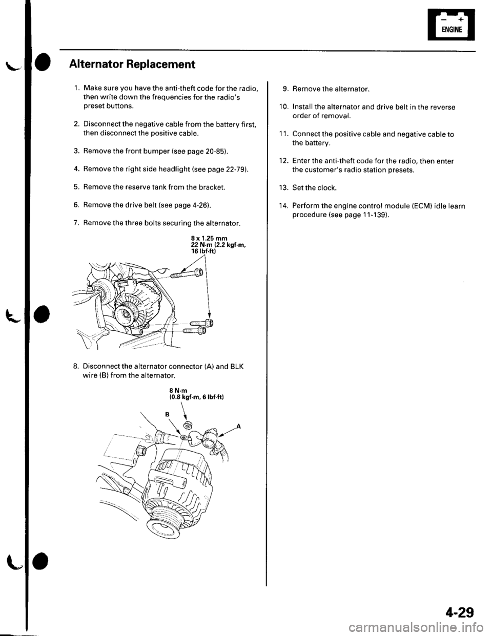
7. Remove the three bolts securing the alternator.
8 x 1.25 mm22 N.n 12.2 kgl.m,
Disconnect the alternator connector (A) and BLK
wire (B) from the alternator.
8 N.m10.8 kgf.m,6lbf.ft)
\
6
'I 1.
9.
10.
13.
14.
Remove the alternator.
Installthe alternator and drive belt in the reverse
order of removal.
Connect the positive cable and negative cable to
the battery.
Enter the anti-theft code for the radio, then enter
the customer's radio station presets.
Set the clock.
Perform the engine control module {ECM) idle learn
procedure (see page 11-139).
tt.
4-29
Page 65 of 1139
Charging System
Alternator Overhaul
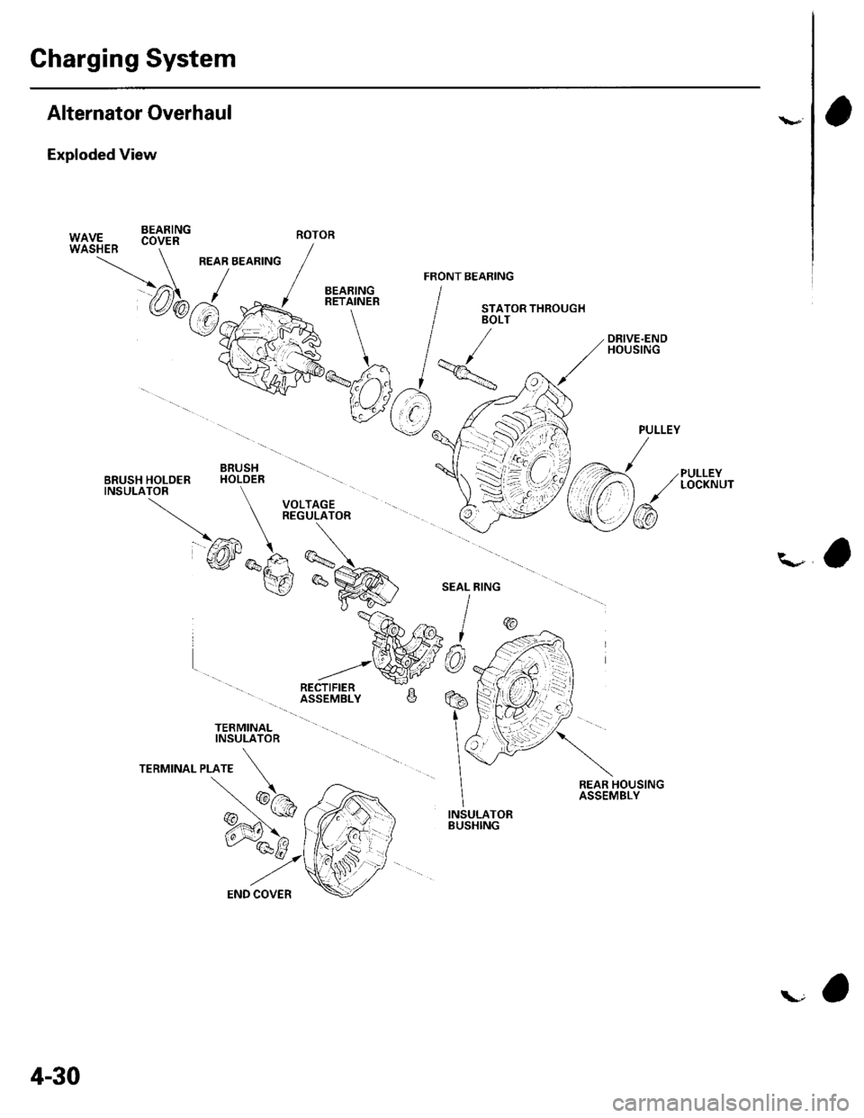
Exploded View
BEARING
PULLEYLOCKNUT
\-a
TERMINALINSULATOR
REAR HOUSINGASSEMBLY
INSULATORBUSHING
PULLEY
/
\/
/@
W|UF., .oy." -
/
REAR BEARING / ,/ ./ FRoNr B
@b.J.y{=RE+LN'"'
IvVFko"-% /
qtr*njlv
V( r),
"V
BRUSH \11BRUSH HOLOER HOLDER -\
TNSULATOR \l VOLTAGE }
\-
REGULATOR (-
@*F, -\:
v_re *^i
\gP^@' I
*ffilw9
ROTOR
4-30
Page 66 of 1139
L
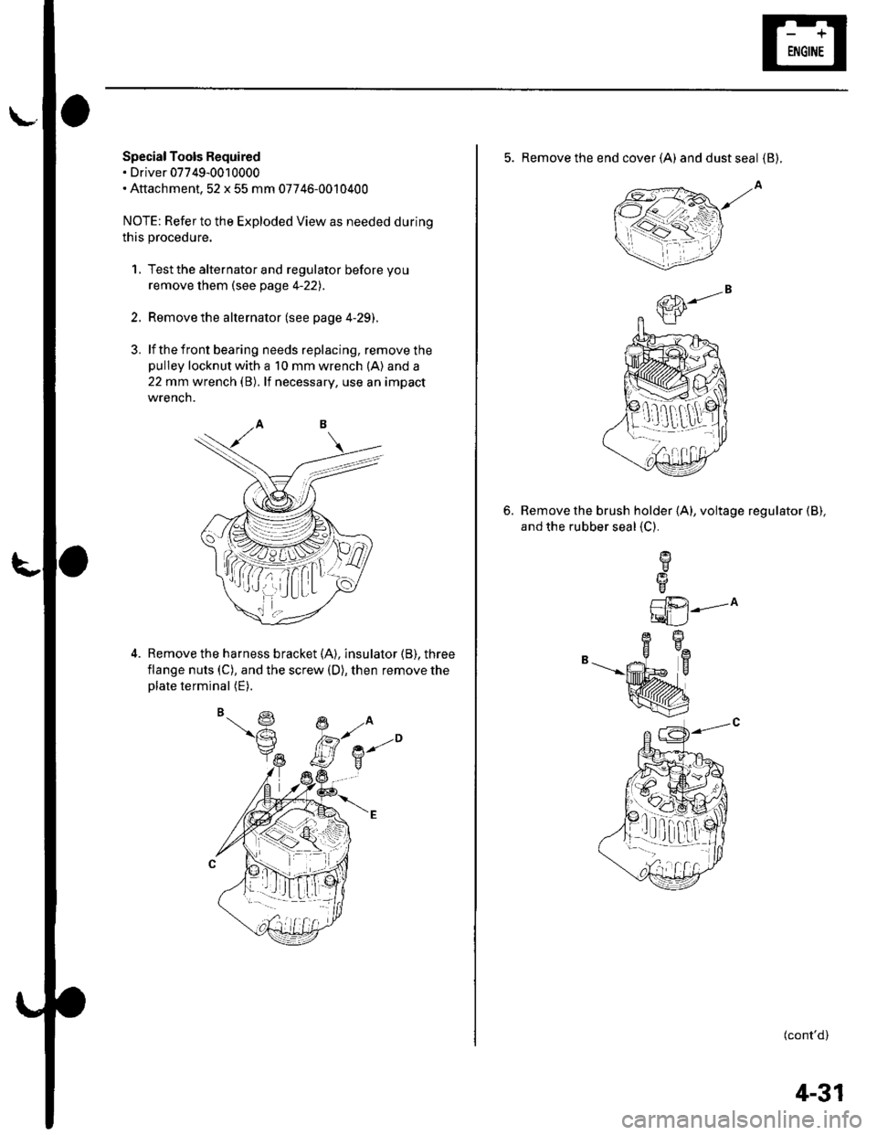
Special Tools Required. Driver 07749-0010000. Attachment,52 x 55 mm 07746-0010400
NOTE: Refer to the Exploded View as needed during
this procedure.
1, Test the alternator and regulator before you
remove them (see page 4-22l,.
2. Remove the alternator (see page 4-29).
3. lf the front bearing needs replacing, remove thepulley locknut with a 10 mm wrench (A) and a
22 mm wrench (B). lf necessary, use an impact
wrencn.
Remove the harness bracket (A), insulator (B). three
flange nuts (C), and the screw (D), then remove theplate terminal (E).
,( ( , tt I;r_ lLt
5. Remove the end cover (A) anddustseal {B).
Remove the brush holder (A), voltage regulator (B),
and the rubber seal {C}.
6.
L1i.21---^
tqLJ
B-"--|.
(cont'd)
1!q[-dr,:l
4-31
Page 70 of 1139
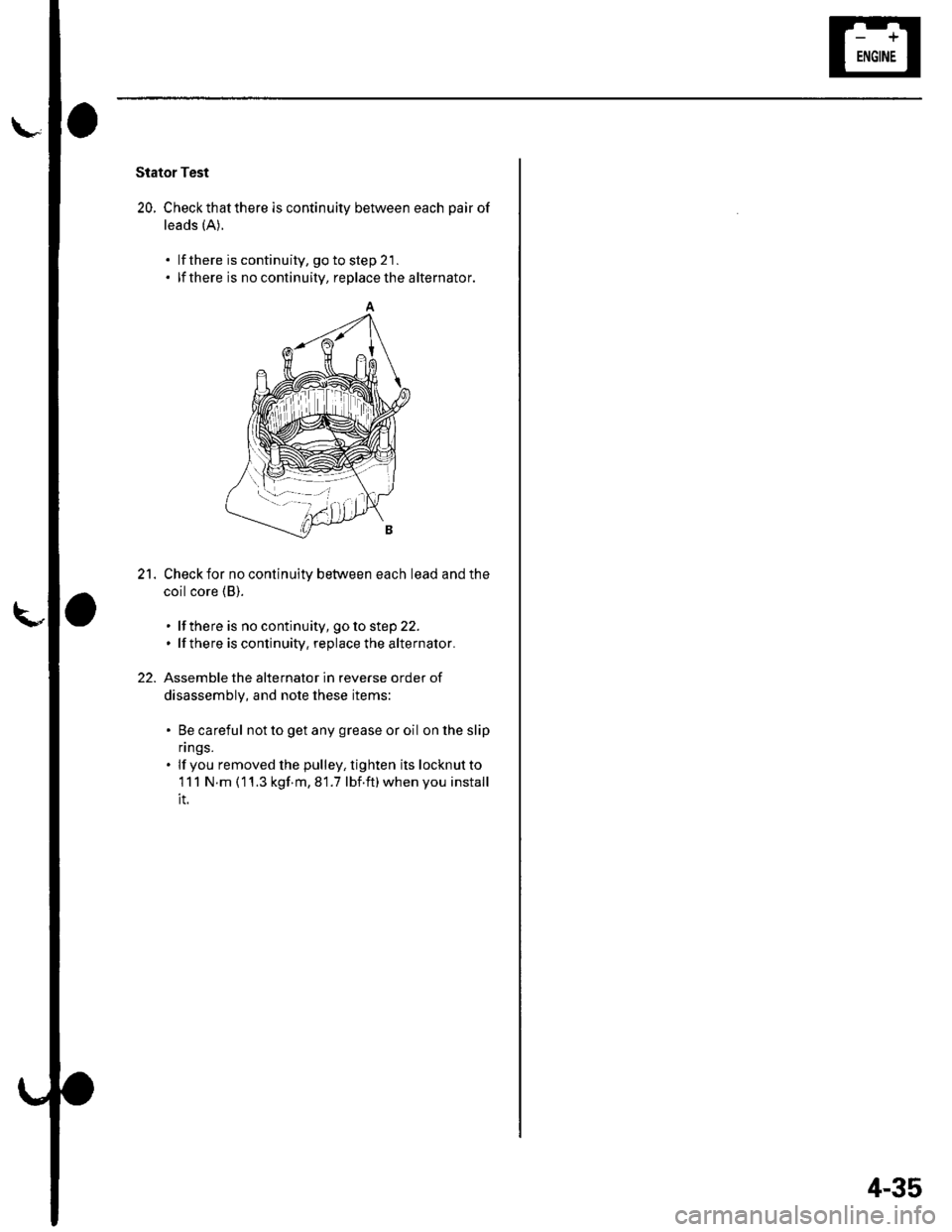
Stator Test
20. Checkthatthere is continuity between each pair of
leads (A).
lf there is continuity, go to step 21 .
lf there is no continuity, replace the alternator.
Check for no continuity between each lead and the
coil core (B).
. lf there is no continuity, goto step 22.. lfthere is continuity, replace the alternator.
Assemble the alternator in reverse order of
disassembly, and note these items:
. Be careful not to get any grease or oil on lhe slip
n ngs.. lf you removed lhe pulley, tighten its locknutto
111 N.m (11.3 kgf m,81.7 lbf.ft)whenyou install
it.
21.
22.
'--l-- --i
4-35
Page 75 of 1139
Cruise Gontrol
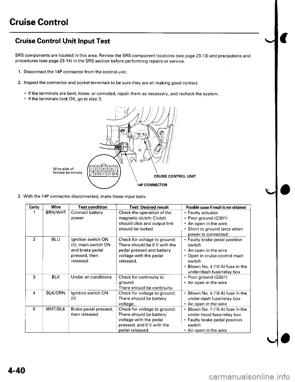
Cruise Control Unit Input Test
SRS components are located in this area. Reviewthe SRS component locations (see page 23-'13) and precautions andprocedures (see page 23-14) in the SRS section before performing repairs or service.
1. Disconnect the 14P connector from the control unit.
2. Inspect the connector and socket terminals to be sure they are all making good contact.
. lf the terminals are bent, loose, orcorroded, repairthem as necessary, and recheckthe system.. lf the terminals look OK, go to step 3.
Wire side offemale terminals
3. With the 14P connector disconnected, make these inDut tests.
CavityWireTest conditionTest: Desired resultPossiblecause ifresuh is not obtained
BRN/WHTConnect battery
power
Check the operation of the
magnetic clutch: Clutch
should click and output link
should be locked.
' Faulty actuator. Poor ground (G301)
. An open in the wire. Shon to ground (arcs when
Dower is connected)
2BLUlgnition switch ON(ll), main swltch ON
and brake pedal
pressed, then
reteaseo
Check for voltage to ground;
There should be 0 V with lhe
pedal pressed and battery
voltage with the pedal
released.
. Faulty brake pedal position
switch. An open in the wire. Open in cruise control main
swrtcn. Blown No. 4 (10 A)fuse in the
under/dash fuse/relav box
3BLKUnder all conditionsCheck for continuity to
grouno:
There should be continuitv
. Poor ground (G501)
. An open in the wire
BLIVORNlgnition switch ON
flr)
Check for voltage to ground:
There should be battery
vottaqe.
Blown No. 4 (10 A)fuse in the
under-dash f use/relay box
An oDen in the wire
5WHT/BLKBrake pedal pressed,
then released
Check for voltage to ground:
There should be battery
voltage with the pedal
pressed, and 0 V with thepedal released.
Blown No. 7 {15 A) fuse in the
under-hood fuse/relay box
Faulty brake pedal position
SWIICN
An oDen in the wire
4-40
Page 78 of 1139
Cruise Control Actuator Test
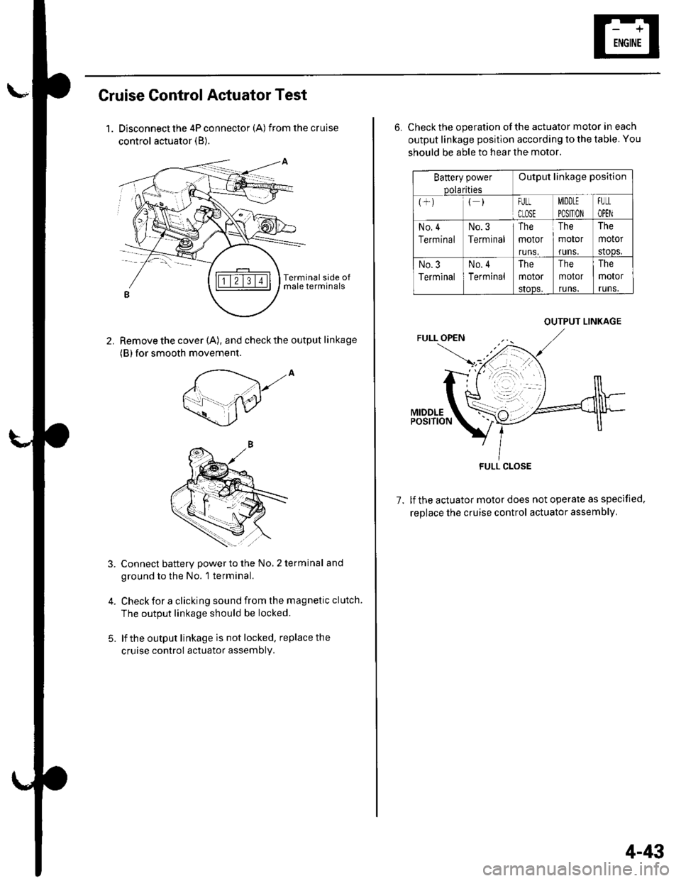
1. Disconnect the 4P connector (A) from the cruise
control actuator (B).
Remove the cover (A), and check the output linkage
(B) for smooth movement.
2.
,to
5.
Connect battery power to the No, 2 terminal and
ground to the No. 1 terminal.
Check for a clicking sound from the magnetic clutch.
The output linkage should be locked.
lf the output linkage is not locked, replace the
cruise control actuator assembly,
6. Check the operation of the actuator motor in each
output linkage position according to the table. You
should be able to hear the motor.
Battery power
Dolarities
Output linkage position
FULt
CLOSE
MIDDLE
PO$TION
FUtL
OPEN
No,4
Terminal
No.3
Terminal
The
motor
runs.
The
motor
runs.
The
motor
stoDs,
No.3
Terminal
No. 4
Terminal
The
motor
sIoos.
The
motor
runs.
The
motor
runs.
1.lf the actuator motor does not operate as specified,
replace the cruise control actuator assembly,
OUTPUT LINKAGE
FULL CLOSE
4-43
Page 79 of 1139
Cruise Control
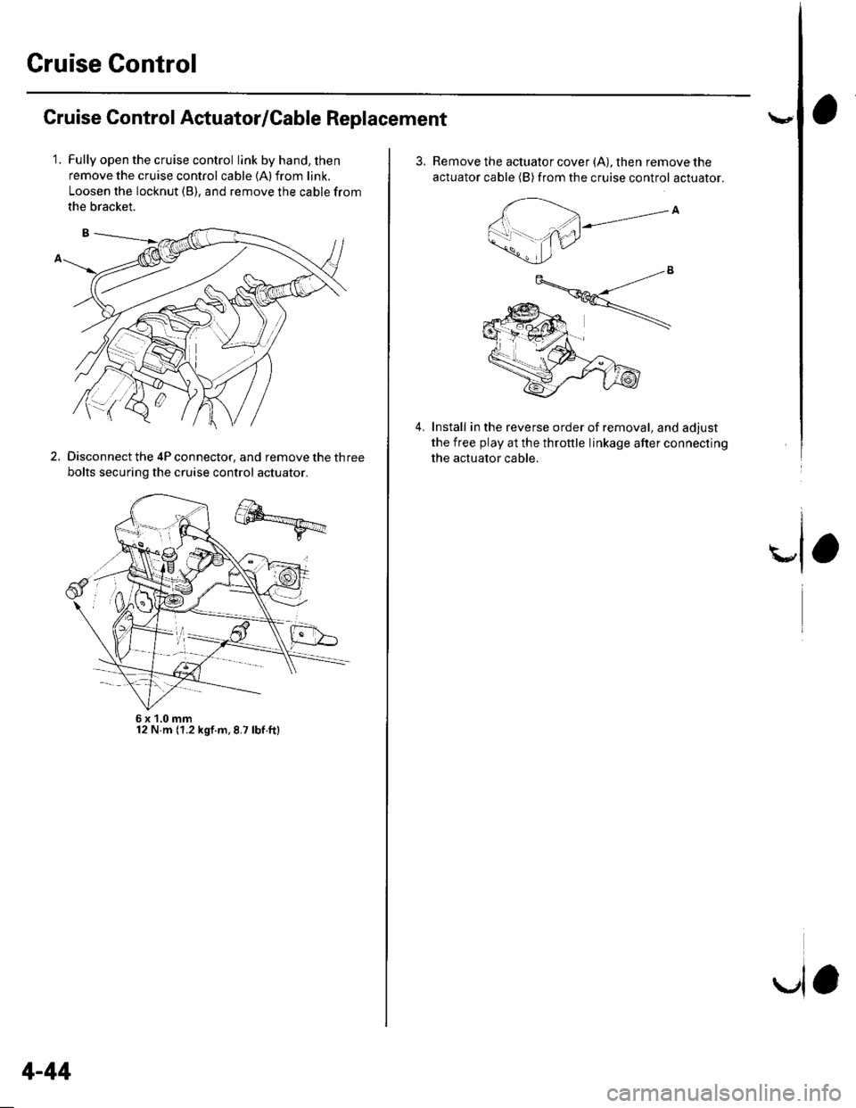
Cruise Control Actuator/Cable Replacement
1.Fully open the cruise control link by hand, then
remove the cruise control cable {A) from link.
Loosen the locknut (B), and remove the cable from
the bracket.
Disconnect the 4P connector, and remove the three
bolts securing the cruise control actuator.
2.
6x1,0mm12 N.m (1.2 kgf.m,8.7 lbf.ft)
4-44
la
3.Remove the actuator cover (A), then remove the
actuator cable (B) from the cruise control actuator.
Install in the reverse order of removal, and adjust
the free play at the throttle linkage after connecting
the actuator cable.
4.
Page 80 of 1139
Actuator Cable Adiustment
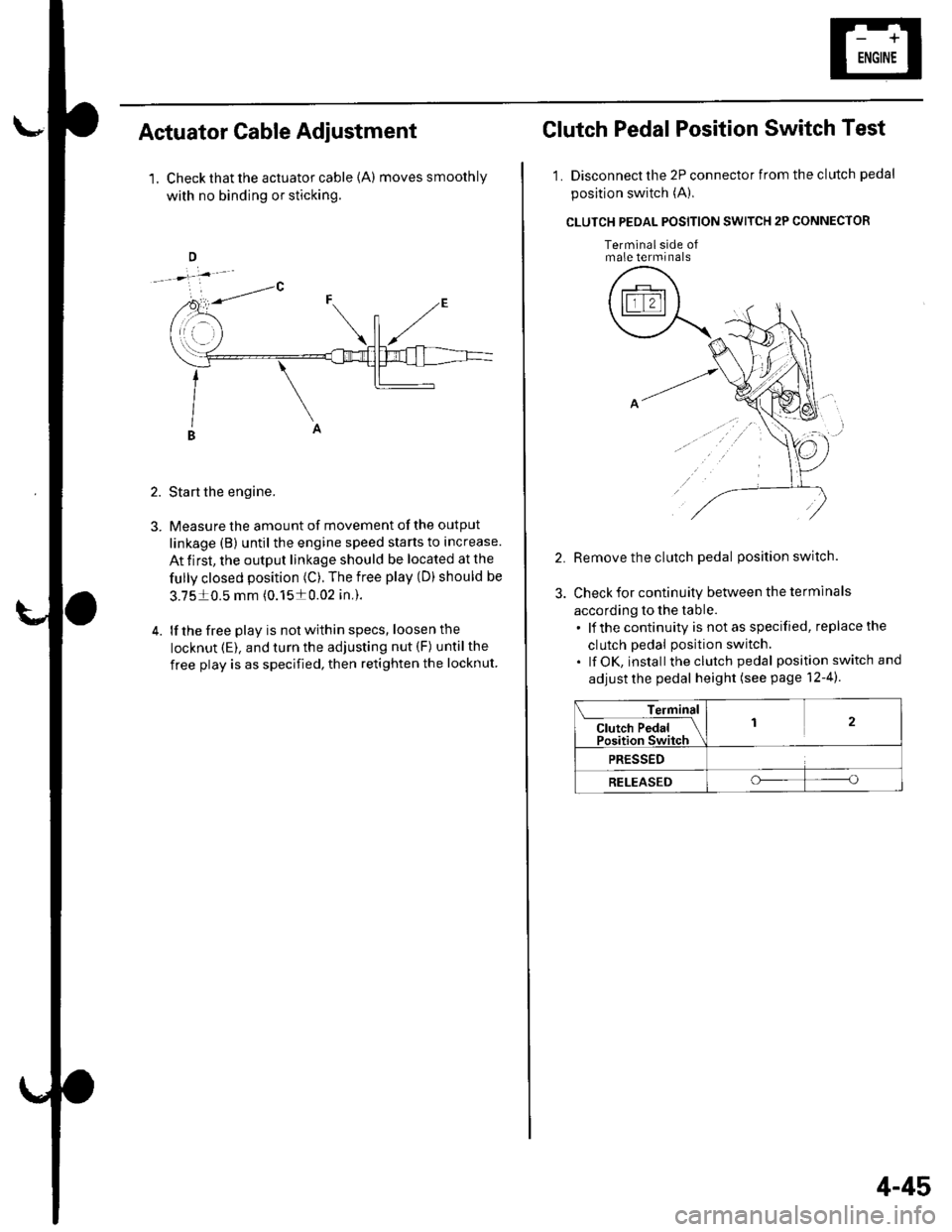
1. Check that the actuator cable {A) moves smoothly
with no binding or sticking.
2. Start the engine.
3. Measure the amount of movement of the output
linkage (B) until the engine speed starts to increase.
At first, the output linkage should be located at the
fully closed position (C). The free play (D) should be
3.7510.5 mm (0.1510.02 in,).
4. lf the free play is not within specs, loosenthe
locknut (E). and turn the adjusting nut (F) untilthe
free play is as specified, then retighten the locknut
Clutch Pedal Position Switch Test
1. Disconnect the 2P connector from the clutch pedal
position switch (A),
CLUTCH PEOAL POSITION SWITCH 2P CONNECTOR
Terminalside ofmale terminals
Remove the clutch pedal position switch.
Check for continuity between the terminals
according to the table.. lf the continuity is not as specified, replace the
clutch pedal position switch.. lf OK, install theclutch pedal position switch and
adjust the pedal height (see page 12-4).
Terminal
Cl"t"h P"d"l IPosition Switch
12
PRESSED
RELEASEDoo
4-45