lock HONDA CIVIC 2002 7.G Service Manual
[x] Cancel search | Manufacturer: HONDA, Model Year: 2002, Model line: CIVIC, Model: HONDA CIVIC 2002 7.GPages: 1139, PDF Size: 28.19 MB
Page 142 of 1139
Engine Block
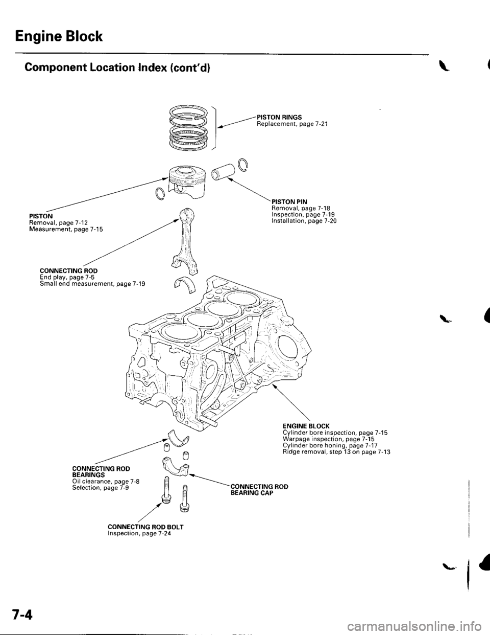
Component Location Index (cont'd)
/^., \
D->< | _,-ersroru nrrucs
Y1 l-"t Benlacement. Page 7-21
rkrej, I
ffil
rG AalQ
[=l^oJ
\
PISTONRemoval, page 7-'12Measurement, page 7-15
PISTON PINRemoval, page 7-18Inspection, page 7-19Installation, page 7,20
f,
6
CONNECTING RODEnd play, page 7-5Small end measurement, page 7-19
CONNECTING ROD
ENGINE BLOCKCylinder bore inspection, page 7-'15Warpage inspection, page 7-15Cylinder bore honing, page 1-11Ridge removai, step 13 on page 7-13
(\
CONNECTING ROD BOLTlnspectaon, page 7 24
7-4
Page 144 of 1139
Engine Block
Crankshaft Main Bearing Replacement
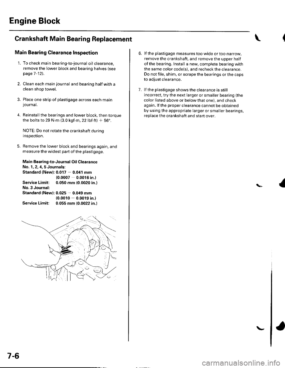
Main Bearing Clearance Inspection
1. To check main bea ring-to-jou rna I oil clearance.
remove the lower block and bearing halves (see
page 1 -12)..
2, Clean each main journal and bearing half witha
clean shop towel.
3. Place one strip of plastigage across each main
lou rnal.
4. Reinstallthe bearings and lower block, then torque
the bolts to 29 N.m {3.0 kgf.m,22 lbf.ft) + 56'.
NOTE: Do not rotate the crankshaft during
Inspeclton.
5. Remove the lower block and bearings again, and
measure the widest part of the plastigage.
Main Bearing-to-Journal Oil Clearance
No. 1,2, 4,5 Journals:
Standard (New): 0.017 0.041 mm
Service Limit:
No.3 Journal:
10.0007 0.0016 in.l
0.050 mm {0.0020 in.)
Standard {Newl: 0.025 - 0.049 mm(0.0010 0.0019 in.)
Service Limit: 0.055 mm (0.0022 in.l
7-6
\.
6. lf the plastigage measures too wide or too narrow,
remove the crankshaft. and remove the upper half
ofthe bearing. Install a new, complete bearing with
the same color code{s), and recheck the clearance.
Do not file, shim, or scrape the bearings or the caps
to adjust clearance.
7. lf the plastigage shows the clearance is still
incorrect, try the next larger or smaller bearing (the
color listed above or below that one), and check
again. lf the proper clearance cannot be obtained
by using the appropriate larger or smaller bearings,
replace the crankshaft and start over.
Page 145 of 1139
Main Bearing Selection
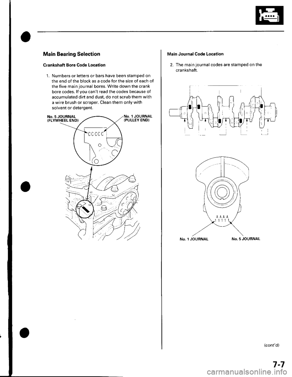
Crankshaft Bore Code Location
1. Numbers or letters or bars have been stamped on
the end of the block as a code for the size of each of
the five main journal bores. Write down the crank
bore codes. lf you can't read the codes because of
accumulated dirt and dust, do not scrub them with
a wire brush or scraper. Clean them only with
solvent or detergent.
No. 1 JOURNALIPULLEY END}No. 5 JOURNAL{FLYWHEEL END)
Main Journal Code Location
2. The main journal codes a{e stamped on the
cra n kshaft.
No. 1 JOURNALNo. 5 JOURNAL
(cont'd)
7-7
Page 146 of 1139
Engine Block
Crankshaft Main Bearing
Replacement (cont'd)
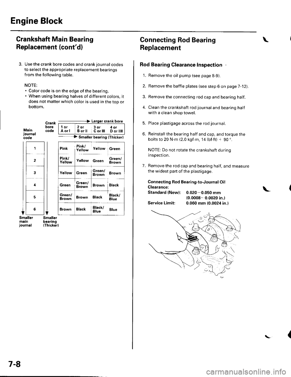
3. Use the crank bore codes and crank journal codes
to select the appropriate replacement bearings
from the following table.
NOTE:. Color code is on the edge of the bearing.. When using bearing halves of different colors. it
does not matter which color is used in the top or
bottom.
Mainiournslcooe
Crank ---=-> Lalger crank bore
bore | 1or 2ot 3or c oi__-lcode IAorl Borll Corlll Dortttt I-- --> Smaller bearing {Thickerl
(Thicker)
1
2
4
5
Pink f!1f;* v"rro* c,""n
ll
f111f;,," v"no* c,""" $;;fl
cr""n $ffi ero-n
ffi#Tr,.*" i.,""*Creen ; g=jiff;i Brown Black
;;lT]*
'---l-'o"*,
Brown Black 6il;
Brack !l;kr ar*
7-8
Connecting Rod Bearing
Replacement
Rod Bearing Clearance lnspection
1. Remove the oil pump (see page 8-9).
2. Bemove the baffle plates (see step 6 on page 7-12).
3. Remove the connecting rod cap and bearing half.
4. Clean the crankshaft rod journal andbearinghalf
with a clean shop towel.
5. Place plastigage across the rod journal.
6. Reinstallthe bearing half and cap, and torque the
bolts to 20 N.m (2.0 kgf.m, 14lbf.ft) -l 90 ".
NOTE: Do not rotate the crankshaft during
inspection.
7. Remove the rod cap and bearing half, and measure
the widest part of the plastigage.
Connecting Rod Bearing-to-Journal Oil
Clearance:
Standard {Newl: 0.020 0.050 mm(0.0008 --0.0020 in.l
Service Limit: 0.060 mm (0.0024 in.)
\
\-
{
Page 148 of 1139
Engine Block
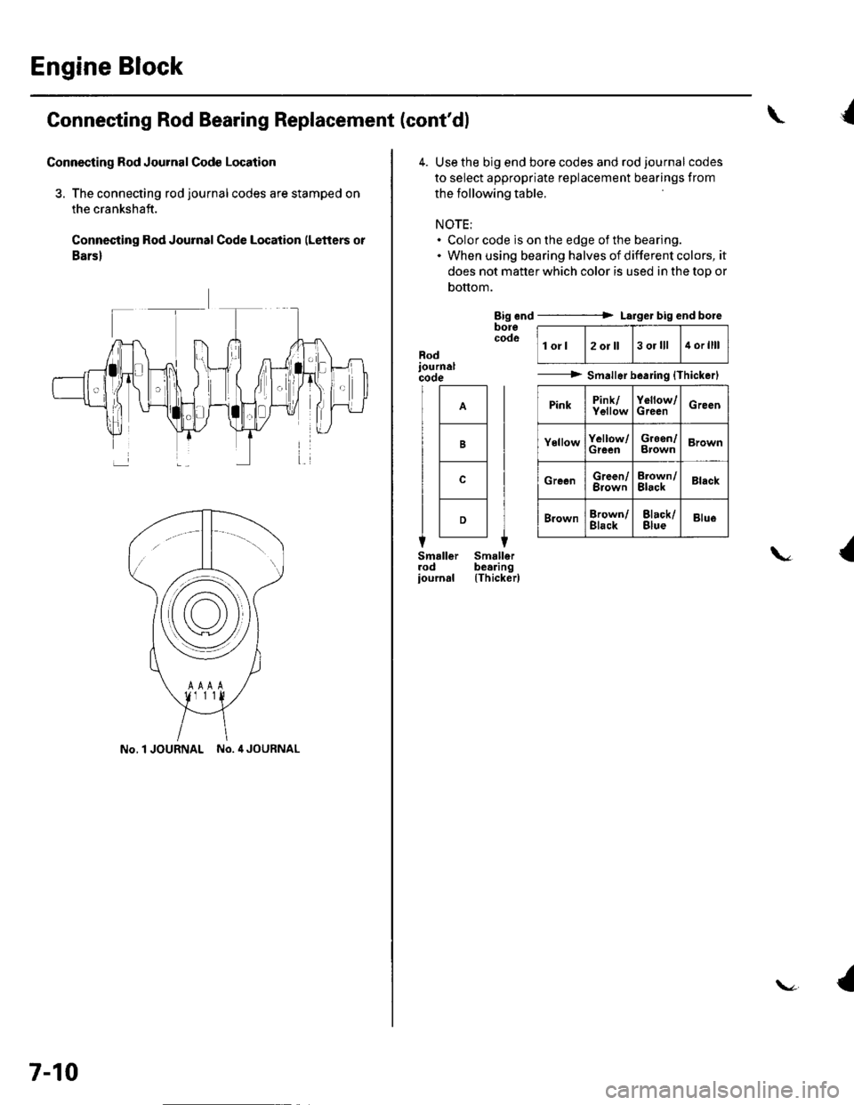
Connecting Rod Bearing Replacement (cont'dl
Connecting Rod Journal Code Location
3. The connecting rod journalcodes are stamped on
the crankshaft.
Connecting Rod Journal Code Location (Letters or
Bars)
No.l JOURNAL No. 4 JOURNAL
7-10
\{
4. Use the big end bore codes and rod journalcodes
to select appropriate replacement bearings from
the following table.
NOTE:. Color code is on the edge of the bearing.. When using bearing halves of different colors, it
does not matter which color is used in the top or
bottom.
Big end ----------> Larger big end boreborecodolorl2oJll3 ol lll4 orllll
---------> Smallsrb.aring {Thickerl
PinkPink/YellowYollow/GrecnGreen
YellowYellow/GreenGreen/BrownBrown
GreenGreen/BrownErown/BlackBlack
BrownBrown/BlackBlack/BlueBlue
Rod
B
c
D
{\
(Thicker)
{
Page 149 of 1139
1.
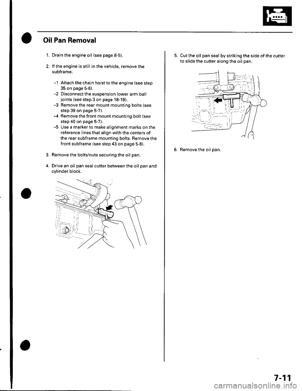
OilPan Removal
Drain the engine oil (see page 8-5).
lf the engine is still in the vehicle, remove the
subframe.
-1 Attach the chain hoist to the engine (see step
35 on page 5-6).-2 Disconnectthe suspension lower arm balljoints (see step 3 on page 18-19).-3 Remove the rear mounl mounting bolts (see
step 39 on page 5-7).-4 Remove the front mount mounting bolt (see
step 40 on page 5-7).-5 Use a marker to make alignment marks on the
reference lines that align with the centers of
the rear subframe mounting bolts. Remove the
front subframe (see step 43 on page 5-8).
Remove the bolts/nuts securing the oil pan.
Drive an oil pan seal cutter between the oil pan and
cylinder block.
5. Cut the oil panseal bystrikingthesideofthecutter
to slide the cutter along the oil pan.
6. Remove the oil pan.
7-11
Page 150 of 1139
Engine Block
Crankshaft and Piston Removal
1. Remove the engine assembly (see page 5-2).
2. Remove the transmission (see page 13-4).
3. Remove the oil pan (see page 7-1 1).
4. Remove the oil pump {see page 8-9).
5. Remove the cylinder head (see page 6-23).
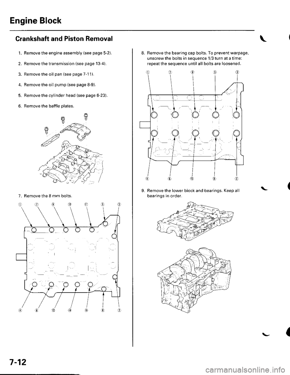
6. Remove the baffle plates.
7. Remove the 8 mm bolts.
E
7-12
8. Remove the bearing cap bolts. To prevent warpage,
unscrew the bolts in sequence 1/3 turn at a time:
repeat the sequence until all bolts are loosened.
Remove the lower block and bearings, Keep all
bearings in order.
\L
(
Page 151 of 1139
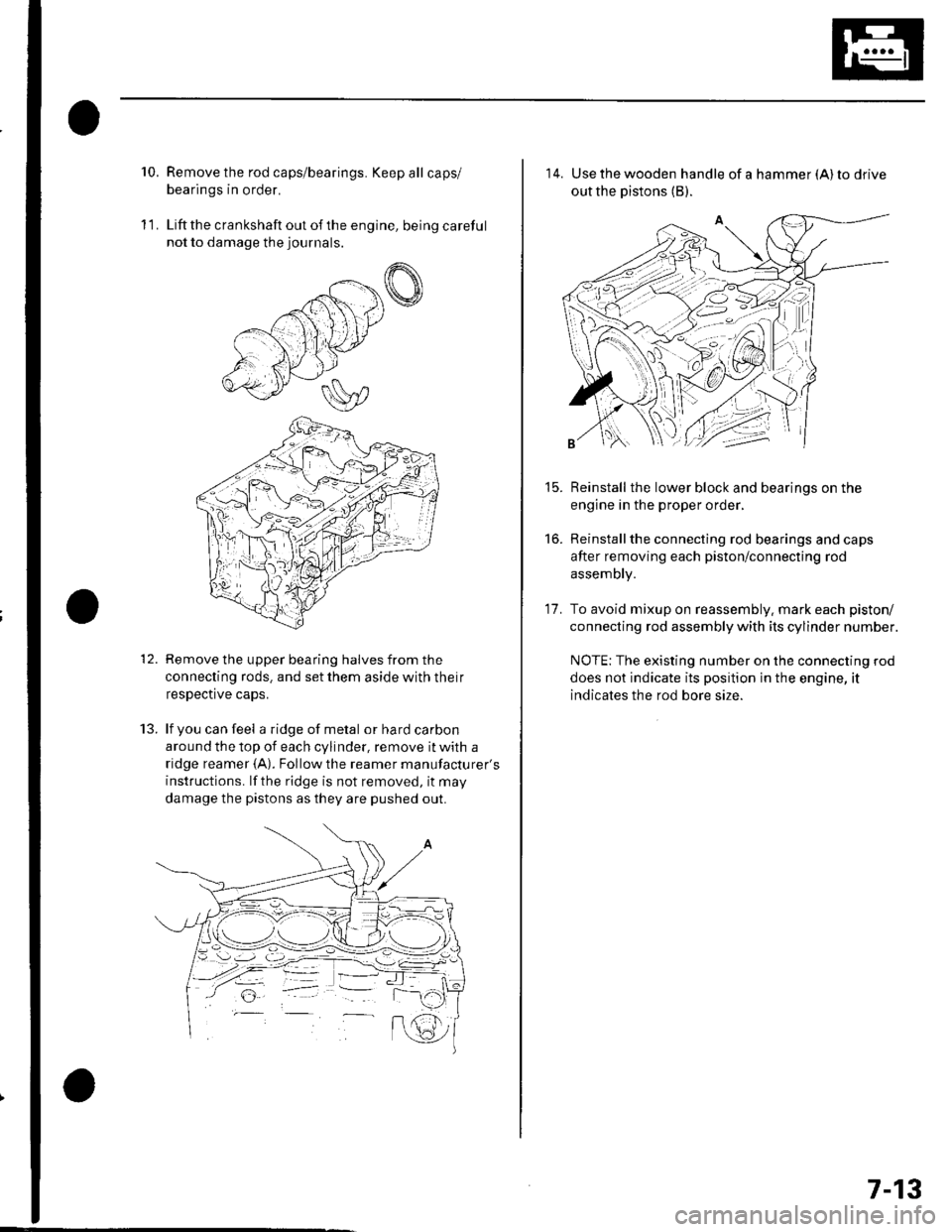
10.Remove the rod caps/bearings. Keep all caps/
bearings in order.
Liftthe crankshaft out ofthe engine, being careful
not to damage the journals.
Remove the upper bearing halves from the
connecting rods. and set them aside with their
respective caps.
lf you can feel a ridge of metal or hard carbon
around the top of each cylinder, remove it with a
ridge reamer {A). Followthe reamer manufacturer's
instructions. lf the ridge is not removed, it may
damage the pistons as they are pushed out.
11.
t.J.
14. Use the wooden handle of a hammer (A) to drive
out the pistons (B).
Reinstall the lower block and bearings on the
engine in the proper order,
Reinstallthe connecting rod bearings and caps
after removing each piston/connecting rod
assembly.
To avoid mixup on reassembly. mark each piston/
connecting rod assembly with its cylinder number.
NOTE: The existing number on the connecting rod
does not indicate its position in the engine, it
indicates the rod bore size.
15.
to.
17.
7-13
Page 152 of 1139
Engine Block
Crankshaft lnspection
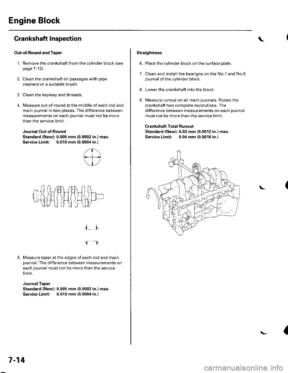
Out-ol-Round and Taper
1. Remove the crankshaft from the cylinder block (see
page 7-121.
2. Clean the crankshaft oil passages with pipe
cleaners or a suitable brush.
3. Clean the keyway and threads.
4. Measure out-of round at the middle of each rod and
main journal in two places. The difference between
measurements on each journal must not be more
than the service Iimit.
Journal Out-ot-Round
Standard (New): 0.005 mm (0.0002 in.) max.
Service Limit; 0.010 mm (0.0004 in.)
5. Measure taper at the edges of each rod and mainjournal. The difference between measurements on
each journal must not be more than the service
limit.
JournalTaper
Standard lNewl: 0.005 mm (0.0002 in.) max.
Service Limit: 0.010 mm {0.0004 in.)
I_JJ
fl
7-14
\
Straightness
6. Place the cylinder block on the surface plate.
7. Clean and installthe bearigns on the No.1 and No.5journal of the cylinder block.
8. Lower the crankshaft into the block.
9. Measure runout on all main journals. Rotate the
crankshaft two complete revolutlons. The
difference between measurements on each journal
must not be more than the service limit.
Crankshaft Total Runout
Standard (New): 0.03 mm 10.0012 in.l max.
Service Limit: 0.04 mm (0.0016 in.l
(L
{
Page 153 of 1139
1.
Block and Piston Inspection
Remove the crankshaft and pistons (se e pageT -121.
Check the piston for distortion or cracks,
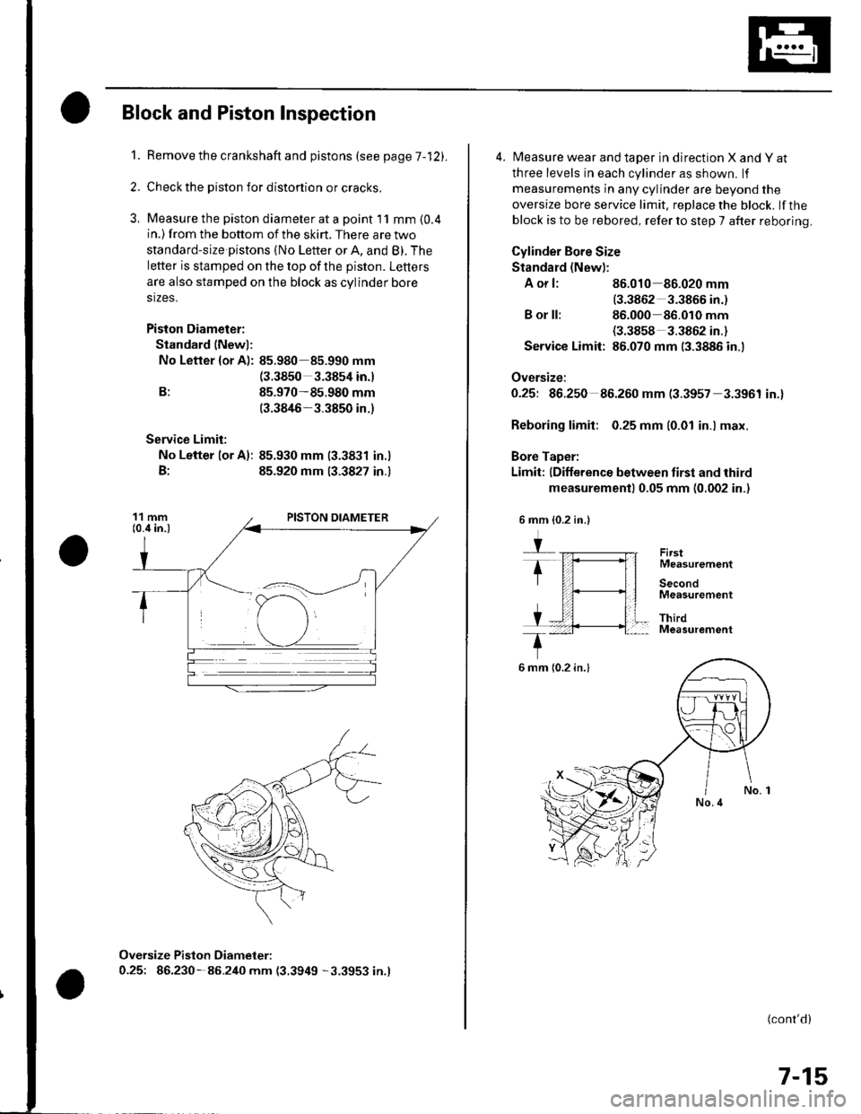
Measure the piston diameter at a point I1 mm {0.4in.) from the bottom of the skirt. There are two
standard-size pistons (No Letter or A, and B). The
letter is stamped on the top of the piston. Letters
are also stamped on the block as cylinder bore
stzes.
Piston Diameter:
Standard (Newl:
No Letter {or A): 85.980 85.990 mm(3.3850 3.3854 in.)
B: 85.970-85.980 mm(3.3846-3.3850 in.)
Service Limit:
No Lefter lor A): 85.930 mm (3.3831 in.)
B: 85.920 mm 13.3827 in.)
Oversize Piston Diameter:
0.25: 86.230-85.240 mm (3.3949 -3.3953 in.l
4. Measure wear and taper in direction X and Y at
three levels in each cylinder as shown. lf
measurements in any cylinder are beyond the
oversize bore service limit. replace the block. lf the
block is to be rebored, refer to step 7 after reboring.
Cylinder Bore Size
Standard (New):
A or l: 86.010 86.020 mm
13.3862 3.3866 in.)
B or ll: 86.000 86.010 mm(3.3858 3.3862 in.)
Service Limit: 86.070 mm (3.3886 in.)
Oversize:
O.25t 96.250 86.260 mm (3.3957 3.3961 in.)
Reboring limit: 0.25 mm (0.01 in.l max.
Bore Taper:
Limit: (Difference between first and third
measurement) 0.05 mm (0.002 in.)
FirstMeasurement
SecondMeasutement
ThirdMeasurement
(cont'd)
7-15
6 mm {0.2 in.}
6 mm {0.2 in.}