lock HONDA CIVIC 2002 7.G Owner's Guide
[x] Cancel search | Manufacturer: HONDA, Model Year: 2002, Model line: CIVIC, Model: HONDA CIVIC 2002 7.GPages: 1139, PDF Size: 28.19 MB
Page 112 of 1139
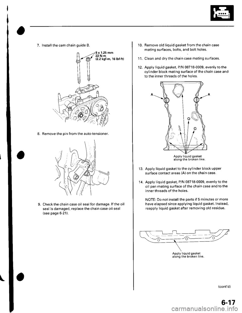
7, Install the cam chainguide B.
H4
\ilt
Hgq
8 x 1.25 mm22 N.m(2.2 kgf.m, 16lbt.ft)
8. Remove the Din from the auto-tensioner,
Check the chain case oil seal for damage. lf the oil
seal is damaged, replace the chain case oil seal
(see page 6-21).
9.
10.
11.
Remove old liquid gasket from the chain case
mating surfaces, bolts, and bolt holes.
Clean and dry the chain case mating surfaces.
Apply liquid gasket. P/N 08718-0009, evenly to the
cylinder block mating surface ofthe chain case and
to the inner threads of the holes.
Apply liquid gasket to the cylinder block upper
surface contact areas (A) on the chain case.
Apply liquid gasket, PiN 08718-0009, evenly to the
oil pan mating surface of the chain case and to the
inner threads of the holes.
NOTE: Do not installthe parts it 5 minutes or more
have elapsed since applying liquid gasket. lnstead,
reapply liquid gasket after removing old residue.
(cont'd)
14.
Apply liquid gasketalong the broken line.
Apply liquid gasketalong the broken line.
6-17
Page 113 of 1139
Gylinder Head
Cam Chain Installation (cont'd)
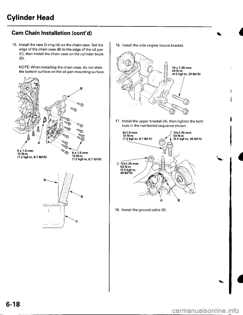
'15. Install the new O-ring (A) on the chain case. Set the
edge of the chain case (B) to the edge of the oil pan(C), then install the chain case on the cvlinder block(D).
NOTE: When installing the chain case, do not slide
the bottom surface on the oil pan mounting surface.
',.9
6x1.0mm12 N.m(1.2 kgt.m.8.7 lbf.ft)
6x1.0mm12Nm(1.2 kgf.m,8.7 lbf.ft)
6-18
\-
{t
16. lnstallthe side engine mount.bracket.
17. Installthe upper bracket (A), then tighten the bolv
nuts in the numbered seouence shown.
6x1.0 mm12 N.m{1.2 kgl m, 8.7 lbf ft}
12x1.25 mm54 N.m(5.5 kgt m, 40 lbf.ft)
I\a
18. Install the ground cable (B).
rbf.ft)
Page 114 of 1139
19.
20.
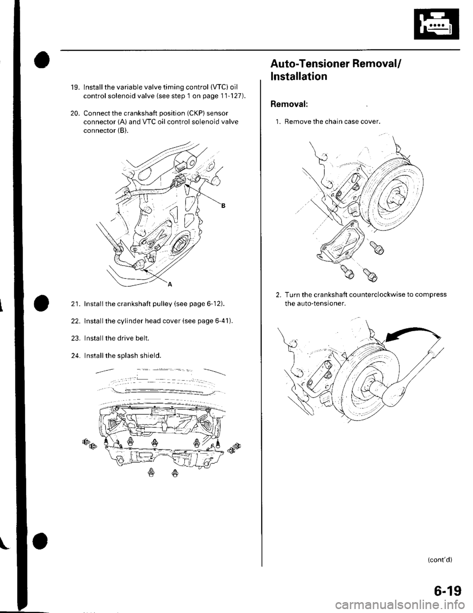
lnstall the variable valve timing control (VTC) oil
control solenoid valve (see step 1 on page 11'127).
Connect the crankshaft position (CKP) sensor
connector {A) and VTC oil control solenoid valve
connector (B).
21. Install the crankshaft pulley (see page 6-12).
22. Installthe cylinder head cover (see page 6-41).
23. Installthe drive belt.
24. Installthe splash shield.
€D@
Auto-Tensioner RemovaU
lnstallation
Removal:
1. Remove the chain case cover.
Turn the crankshaft counterclockwise to compress
the auto-tensroner.
{cont'd)
6-19
Page 115 of 1139
Gylinder Head
Auto-Tensioner Removal/l nstallation
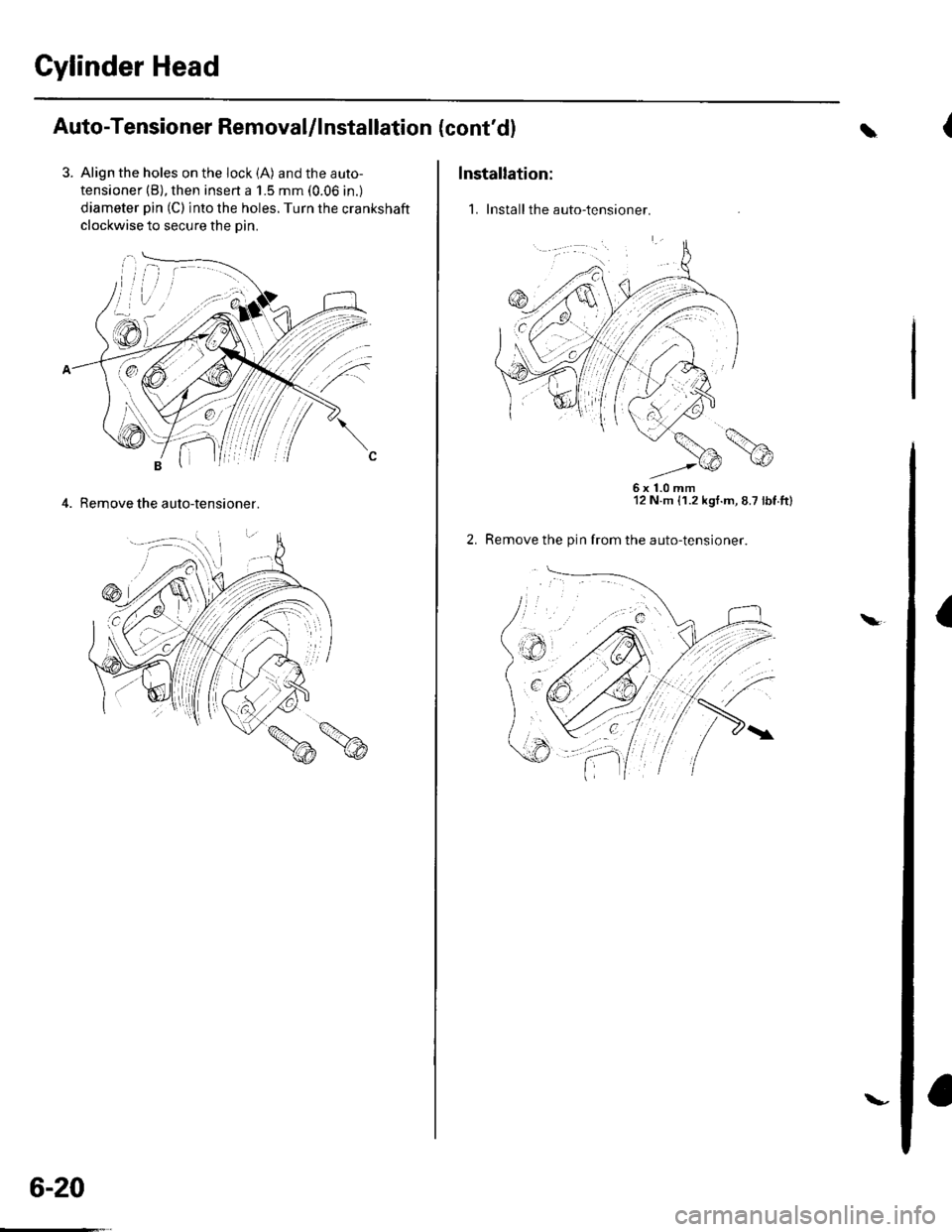
3. Align the holes on the lock (A) and the auto-
tensioner (B), then insert a 1.5 mm (0.06 in.)
diameter pin (C) into the holes. Turn the crankshaft
clockwise to secure the oin.
4. Remove the auto-tensioner.
6-20
\-
(cont'dl
Installation:
1. Install the auto-tensioner.
\
6x1.0mm12 N.m {1.2 kgt.m, 8.7 lbt.tt)
Remove the pin from the auto-tensioner.
a\
Page 125 of 1139
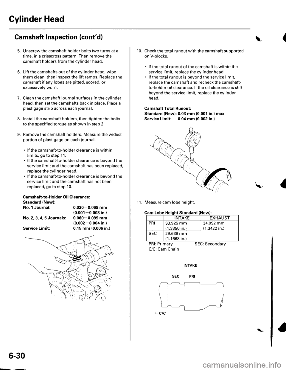
Cylinder Head
Camshaft Inspection (cont'dl
1.
9.
Unscrew the camshaft holder bolts two turns at a
time, in a crisscross pattern. Then remove the
camshaft holders from the cylinder head.
Lift the camshafts out of the cylinder head, wipe
them clean. then inspect the lift ramps. Replace the
camshaft if any lobes are pitted, scored, or
excessively worn,
Clean the camshaft journal surfaces in the cylinder
head, then set the camshafts back in place. Place a
plastigage strip across each journal.
Install the camshaft holders, then tighten the bolts
to the specified torque as shown in step 2.
Remove the camshaft holders. Measure the widest
portion of plastigage on each journal.
. lf the camshaft-to-holder clearance is within
limits, go to step 1 1.. lf the camshaft-to-holder clearance is beyond the
service limit and the camshaft has been replaced,
replace the cylinder head.. lf the camshaft-to-holder clearance is beyond the
service limit and the camshaft has not been
replaced, go to step 10.
Camshaft-to-Holder Oil Clearance:
Standard (New):
No. 1 Journal:
No.2,3,4,5 Journals:
Service Limit:
0.030 0.069 mm
{0.001 0.003 in-)
0.060*0.099 mm
{0.002 0.004 in.)
0.15 mm {0.006 in.)
6-30
\-
{\
10. Check the total runout with the camshaft supported
on V-blocks,
.lfthetotal runout of the camshaft is within the
service limit, replace the cylinder head.. lf the total runout is beyond the service limit,
replace the camshaft and recheck the camshaft-
to-holder oil clearance. lf the oil clearance is still
beyond the service limit, replace the cylinder
neao.
Camshaft Total Runout:
Standard (New): 0.03 mm (0.001 in.) max.
Service Limit: 0.04 mm {0.002 in.)
11. Measure cam lobe height.
Cam
PRI: Primary
C/C: Cam Chain
SEC: Secondary
I\,
Lobe Heioht Standard (New
INTAKEEXHAUST
PRI33.925 mm(1.3356 in.)
34.092 mm
\1 .3422 in.l
SEC29.638 mm(1.1668 in.)
Page 129 of 1139
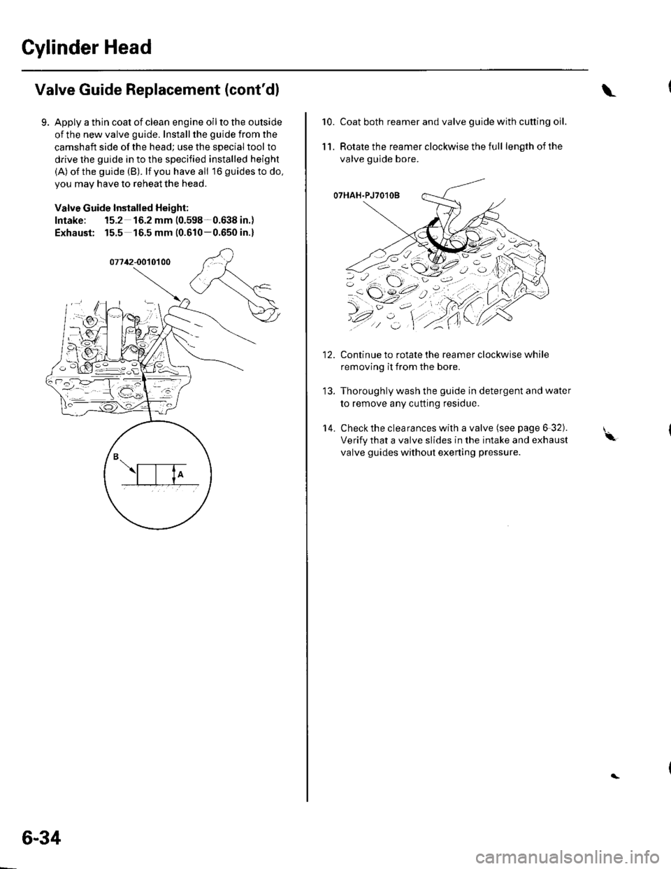
Cylinder Head
Valve Guide Replacement (cont'dl
Apply a thin coat of clean engine oil to the outside
of the new valve guide. Install the guide from the
camshaft side of the head; use the special tool to
drive the guide in to the specified installed height
(A) o{the guide (B). lf you have all 16 guidesto do,
you may have to reheat the head.
Valve Guide Installed Height:
Intake: 15.2 16.2 mm (0.598-0.638 in.)
Exhaust: 15.5 16.5 mm (0.610-0.650 in.)
6-34
\
10.Coat both reamer and valve guide with cutting oil.
Rotate the reamer clockwise the full length of the
valve guide bore.
O7HAH.PJ7O1OB
Continue to rotate the reamer clockwise while
removing it from the bore.
Thoroughly wash the guide in detergent and water
to remove any cutting residue.
Check the clearances with a valve (see page 6 32).
Verify that a valve slides in the intake and exhaust
valve guides without exening pressure.
11.
14.
'-\
Page 134 of 1139
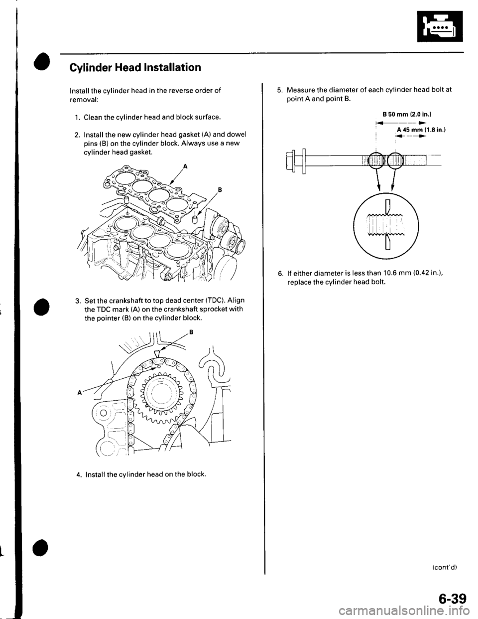
Cylinder Head Installation
Install the cylinder head in the reverse order of
removat:
1. Clean the cylinder head and block surface.
2. Install the new cylinder head gasket (A) anddowel
pins (B) on the cylinder block. Always use a new
cylinder head gasket.
Set the crankshaft to top dead center {TDC). Align
the TDC mark (A) on the crankshaft sprocket with
the pointer (B) on the cylinder block.
4. Install the cylinder head on the block.
5. Measure the diameter of each cylinder head bolt at
ooint A and Doint B.
a 50 mm (2.0 in.l
f.f )>-
A '15 mm {'1.8 in.)"<>.
lf either diameter is less than 10.6 mm {0.42 in.),
replace the cvlinder head bolt.
(cont d)
6-39
Page 139 of 1139
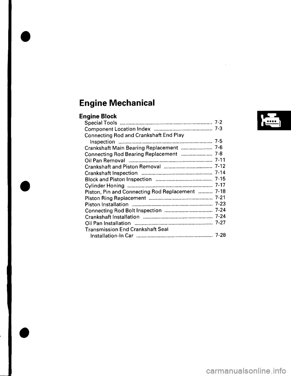
Engine Mechanical
Engine Block
Soecial Tools ............. 7 -2
Comoonent Location Index ......................................... 7-3
Connecting Rod and Crankshaft End Play
InsDection .............. 7-5
Crankshaft Main Bearing Replacement ...................... 7-6
Connecting Rod Bearing Replacement ...................... 7-8
Oil Pan Removal ....................... .......... 7-11
Crankshaft and Piston Removal ........ 7-12
Crankshaft Inspection ........................ 7-14
Block and Piston Insoection ........................................ 7-15
Cyfinder Honing ............ .".................... 7 -'17
Piston, Pin and Connecting Rod Replacement .......... 7-18
Piston Ring Replacement ................... 7 -21
Piston lnstallation .................... ........... 7-23
Connecting Rod Bolt Inspection .......' 7 -24
Crankshaft lnstallation .....................'. 7-24
Oil Pan lnstallation .................. ........... 7 -27
Transmission End Crankshaft Seal
lnstallation-ln Car ................... ........' 7 -28
Page 140 of 1139
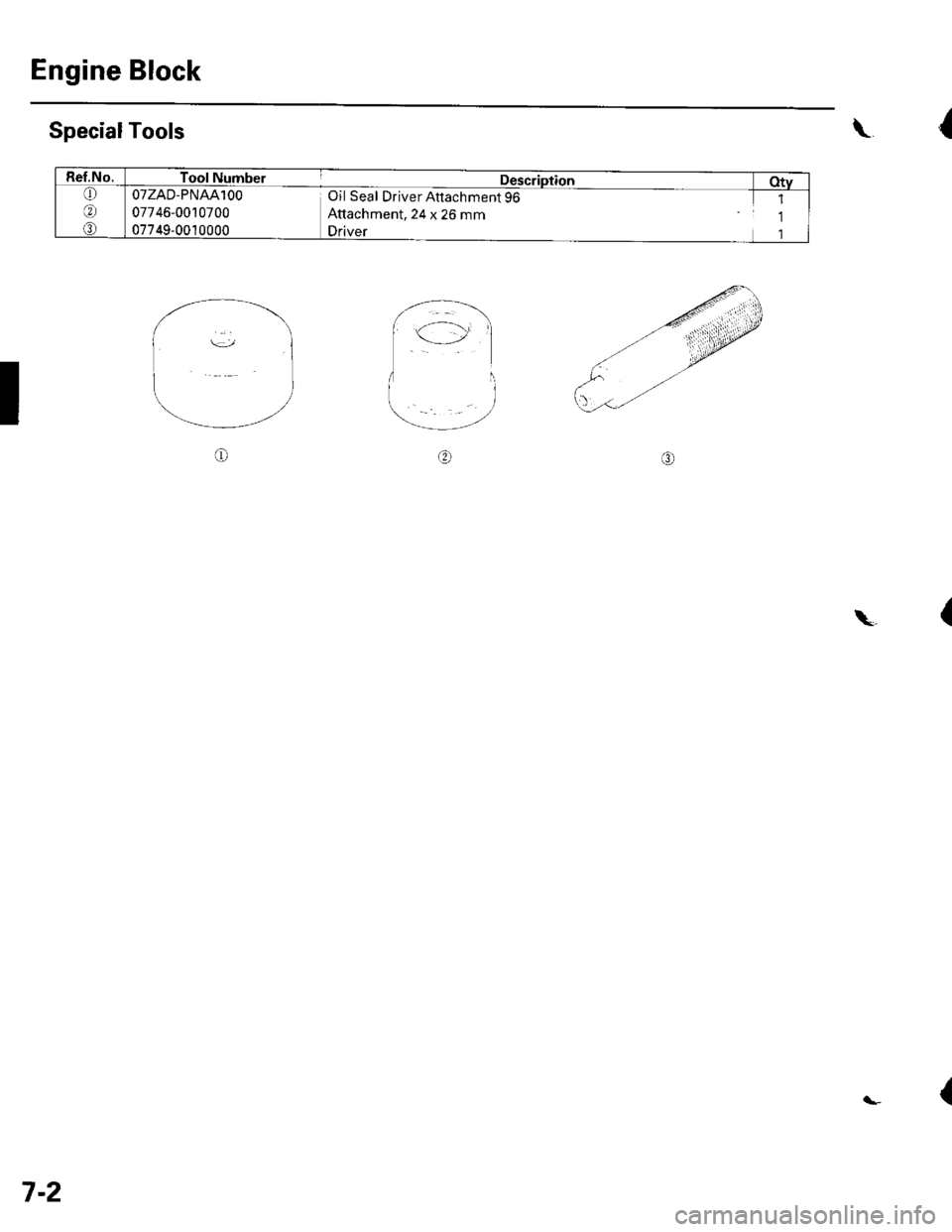
Engine Block
SpecialTools
I
{\
Ref.No.Tool Number
OTZAD-PNAAlOO
07746-0010700
07749,0010000
Description
Oil Seal Driver Attachment 96
Attachment, 24 x 26 mm
Driver
Oty
6
@
1
1
1
o
{\
{
7-2
Page 141 of 1139
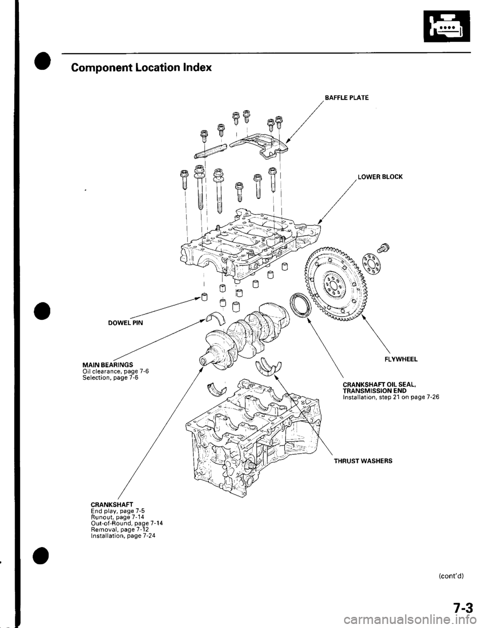
Component Location Index
MAIN BEARINGSOilclearance, page 7-6Selection, page 7-6
CRANKSHAFTEnd play, page 7-5Runout, page 7-14Out-of-Round, page 7-14Removal, page 7-12lnstallation, page 7-24
fifr"8
-4
E
I
BAFFLE PLATE
LOWER BLOCK
FLYWHEEL
CRANKSHAFT OIL SEAL.TRANSMISSION ENDInstallation, step 21 on page 7-26
THRUST WASHERS
(cont'd)
7-3