engine HONDA CIVIC 2002 7.G Owner's Guide
[x] Cancel search | Manufacturer: HONDA, Model Year: 2002, Model line: CIVIC, Model: HONDA CIVIC 2002 7.GPages: 1139, PDF Size: 28.19 MB
Page 84 of 1139
Engine Assembly
Engine Removal (cont'dl
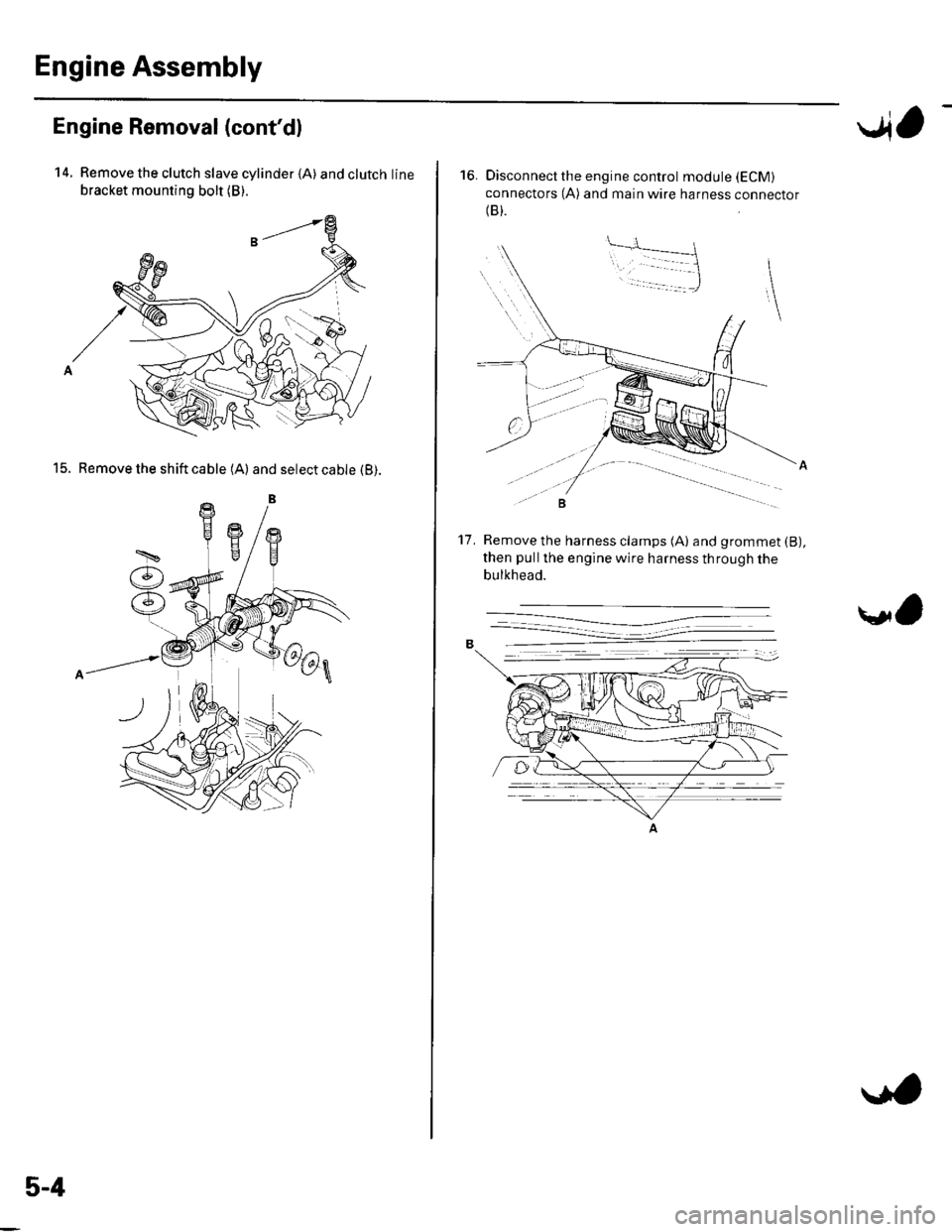
14. Remove the clutch slave cylinder {A) andclutchline
bracket mounting bolt (B).
15. Remove the shift cable (A) and select cable (B).
5-4
..4,
16. Disconnect the engine control module (ECM)
connectors (A) and main wire harness connector(B).
Remove the harness clamps (A) and grommet (B),
then pullthe engine wire harness through the
bulkhead.
't7 .
\l,
Page 85 of 1139
18.
19.
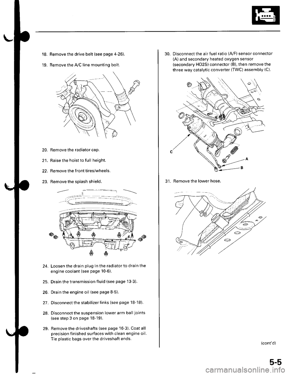
Remove the drive belt (see page 4-26).
Remove the lvC line mounting bolt.
20. Remove the radiator cap.
21. Raise the hoist to full height.
22. Remove the front tires/wheels.
23. Remove the splash shield.
o@
24. Loosen the drain plug in the radiatorto drain the
engine coolant (see page 10-6).
25. Drain the transmission fluid (see page 13'3).
26. Drain the engine oil {see page 8-5).
27. Disconnect the stabilizer links (see page 18-18).
28. Disconnect the suspension lower arm ball joints
(see step 3 on page 18-19).
29. Remove the driveshafts {see page 16-3). Coat all
precision finished surfaces with clean engine oil.
Tie plastic bags over the driveshaft ends.
30. Disconnect the air fuel ratio {4,/F) sensor connector
(A) and secondary heated oxygen sensor
(secondary HO2S) connector (B), then remove the
three way catalytic converter {TWC) assembly {C).
31. Remove the lower hose.
(cont'd)
5-5
Page 86 of 1139
Engine Assembly
Engine Removal (cont'd)
32. Lower the hoist.
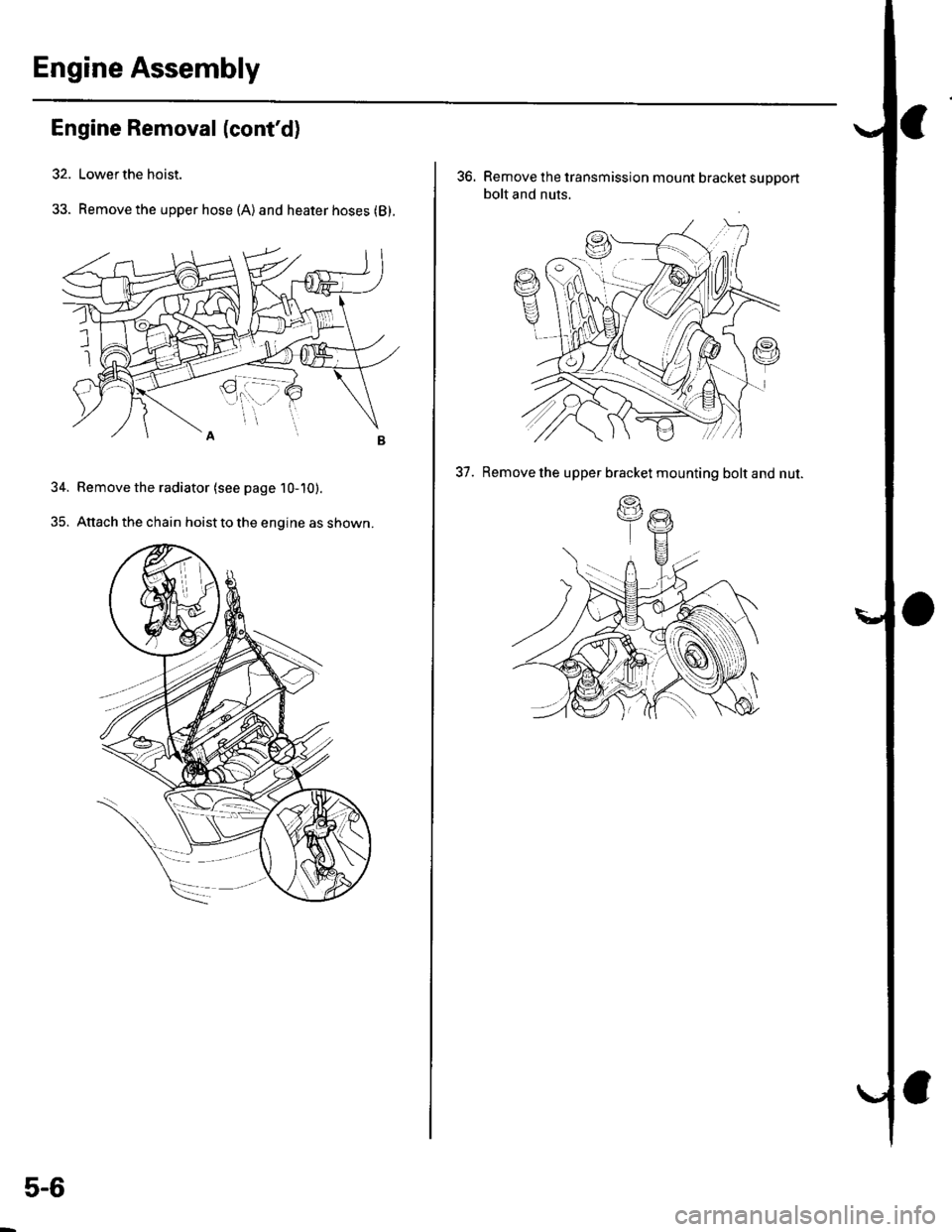
33. Remove the upper hose (A)and heater hoses (B).
34. Bemove the radiator (see page 10-10).
35. Attach the chain hoist to the engine as shown.
5-6
36. Remove the transmission mount bracket support
bolt and nuts.
37. Remove the upper bracket mounting bolt and nut.
(.g
\a
Page 88 of 1139
Engine Assembly
Engine Removal (cont'd)
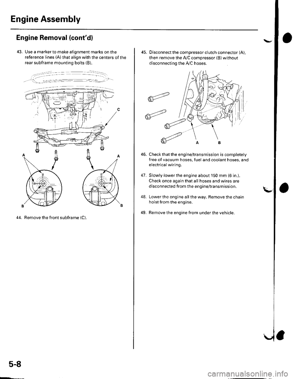
43. Use a marker to make alignment marks on the
reference lines (A) that align with the centers of the
rear subframe mounting bolts (B).
, !:_- _l.= :r -- ---.-','- -
44. Remove the front subframe (C).
5-8
ffi4
ffit'"
45. Disconnect the compressor clutch connector (A),
then remove the Ay'C compressor (B)without
disconnecting the A'./C hoses.
Check that the engine/transmission is completely
free of vacuum hoses, fuel and coolant hoses, and
electrical wiring.
Slowly lower the engine about 150 mm (6 in.).
Check once again that all hoses and wires are
disconnected trom the engine/transmission.
Lower the engine all the way. Remove the chain
hoist from the engine.
Remove the engine from under the vehicle.
46.
47.
48.
49.
Page 89 of 1139
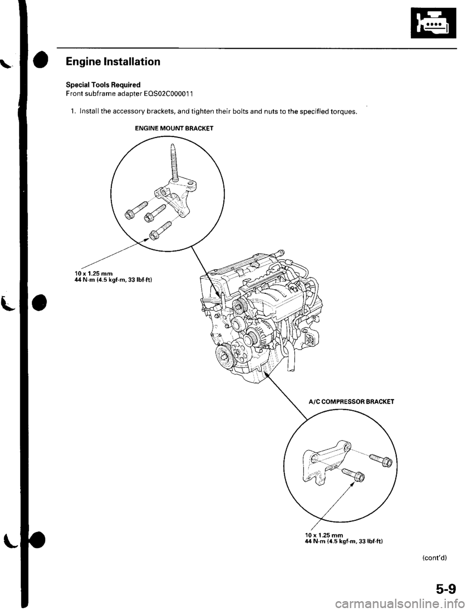
Engine lnstallation
Special Tools Required
Front subframe adapter EOS02C00001 1
1. lnstallthe accessory brackets, and tighten their bolts and nuts to the specified torques.
10 x 1.25 mmil4 N.m {4.5 kgf.m,33lbl.ft)
A/C COMPRESSOR BRACKET
10 x 1 ,25 mm44 N.m {4.5 kgf.m,33lbt.ft)
(cont'dl
ENGINE MOUNT BRACKET
5-9
Page 90 of 1139
Engine Assembly
Engine Installation (cont'd)
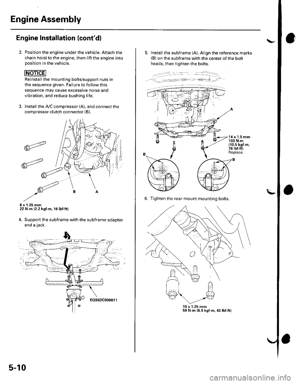
Position lhe engine under the vehicle. Attach the
chain hoist to the engine, then lift the engine intoposition in the vehicle.
Reinstallthe mounting bolts/support nuts in
the sequence given. Failure to follow this
sequence may cause excessive noise and
vibration, and reduce bushing life.
3. Install the A,/C compressor (A), and connect the
compressor clutch connector {B).
8 x 1.25 mm22 N.m 12.2 kgf m. 16 lbf.ft)
4. Support the subframe with the subframe adapter
and a jack.
6r"
6-_-'-
5-10
- - -.'.: - --=---=-- .-€..'tt-
---:-�-�
5. Install the subframe (A). Align the reference marks(B) on the subframe with the center of the bolt
heads, then tighten the bolts.
14x 1.5 mm103Nm{10,5 kgf m.76 rbt.ftlReplace.
6. Tighten the rear mount mounting bolts.
l0x 1.25 mm59 N.m (6.0 kgf.m, 4:] lbI.ft)
FI
Page 91 of 1139
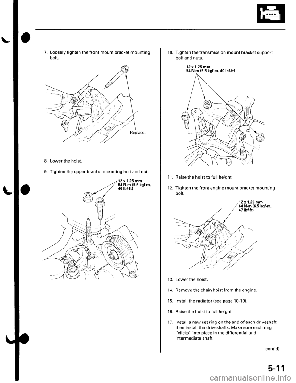
7. Loosely tighten the front mount bracket mounting
bolt.
Lower the hoist.
Tighten the upper bracket mounting bolt and nut.
8.
9.
10. Tighten the transmission mount bracket support
bolt and nuts.
12 x 1.25 mm54 N m {5.5 kgt m, 40 lbf.ft}
Raise the hoist to full height.
Tighten the front engine mount bracket mounting
bolt.
'l '1.
't2.
12 x 1.25 rnrn64 N.m {6.5 kgf.m,47 tbt.ftl
13. Lower the hoist.
14. Remove the chain hoist from the engine.
'15. Installthe radiator (see page 10-10).
'16. Raise the hoist to full height.
17. Install a new set ring on the end of each driveshaft,
then install the driveshafts. Make sure each ring"clicks" into place in the differential and
intermediate shaft.
(cont'd)
:l
5-11
Page 92 of 1139
Engine Assembly
18.
Engine Installation {cont'dl
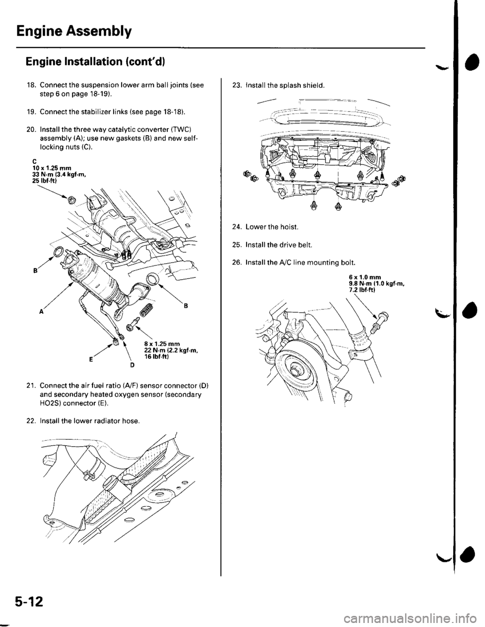
10 x 1.25 mm33 N.m {3.i1kgf.m,25 tbt.ftl
19.
20.
Connect the suspension lower arm ball joints (see
step 6 on page 18-19).
Connect the stabilizer links (see page 18-18).
Install the three way catalytic converter (TWC)
assembly (A); use new gaskets (B) and new self-
locking nuts {C).
\D
21.
-d
,ry6\
8 x 1.25 mm22N.m |.2.2kgl m,16 tbt.ft)
Connect the air fuel ratio (4,/F) sensor connector (D)
and secondary heated oxygen sensor (secondary
HO2S) connector (E).
Install the lower radiator hose.
5-12
va
23. Installthe splash shield.
24.
25.
26.
Lower the hoist.
Installthe drive belt.
Installthe A,/C line mounting bolt.
6 x '!.0 mm9.8 N.m (1.0 kgf.m,7.2 tbt.ftl
. -t- --�- --�--r
Page 93 of 1139
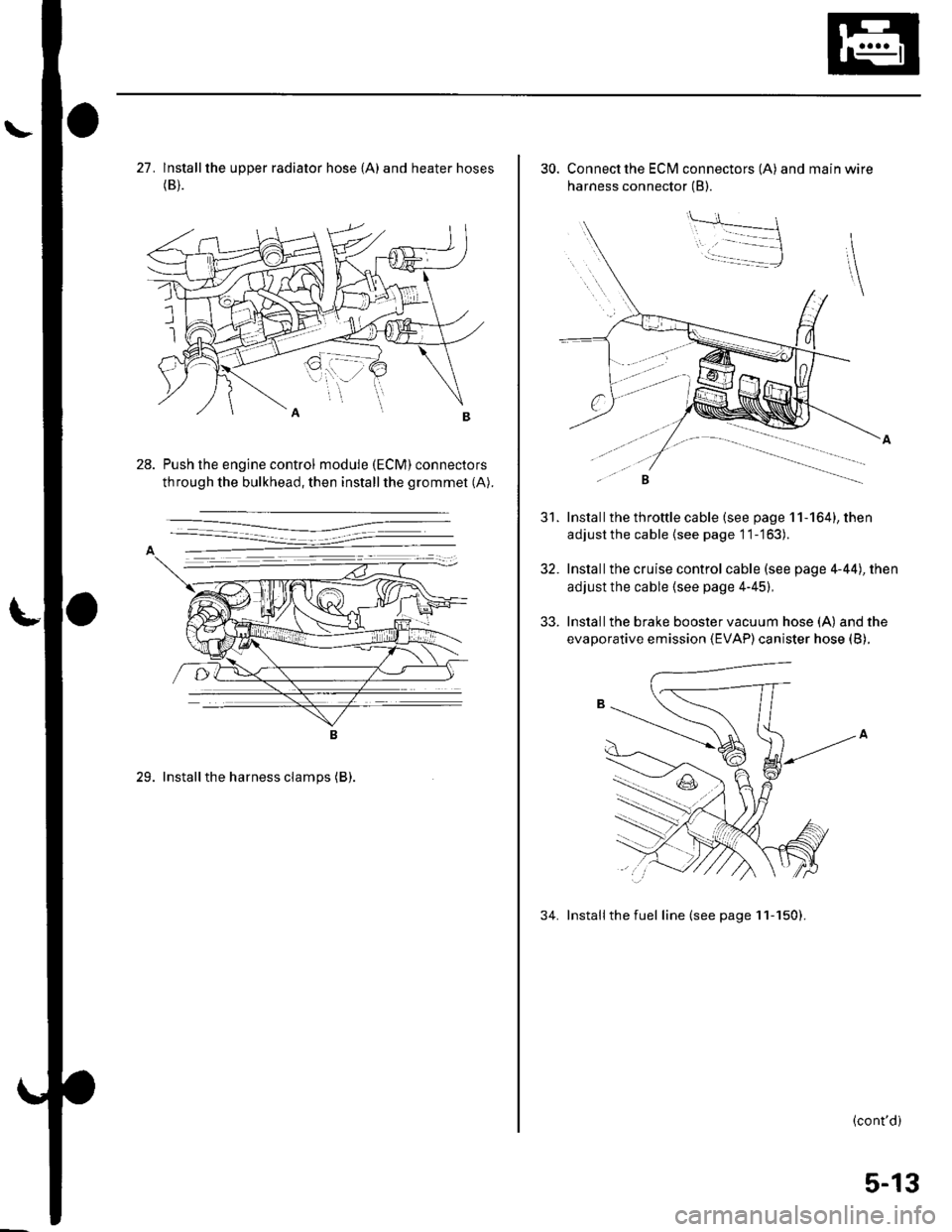
27. lnstallthe upper radiator hose {A) and heater hoses(B).
Push the engine control module (ECM) connectors
through the bulkhead, then installthe grommet (A).
29. Installthe harness clamps (B).
30. Connect the ECI\4 connectors (A) and main wire
harness connector (B).
Install the throttle cable (see page 11-164), then
adjustthe cable {see page 11-'163).
Installthe cruise control cable (see page 4-44), then
adjust the cable (see page 4-45),
Install the brake booster vacuum hose (A) and the
evaporative emission (EVAP) canister hose (B).
34. Installthe fuel line (see page 11-150).
31.
32.
33.
(cont'd)
5-13
Page 94 of 1139
Engine Assembly
Engine Installation {cont'dl
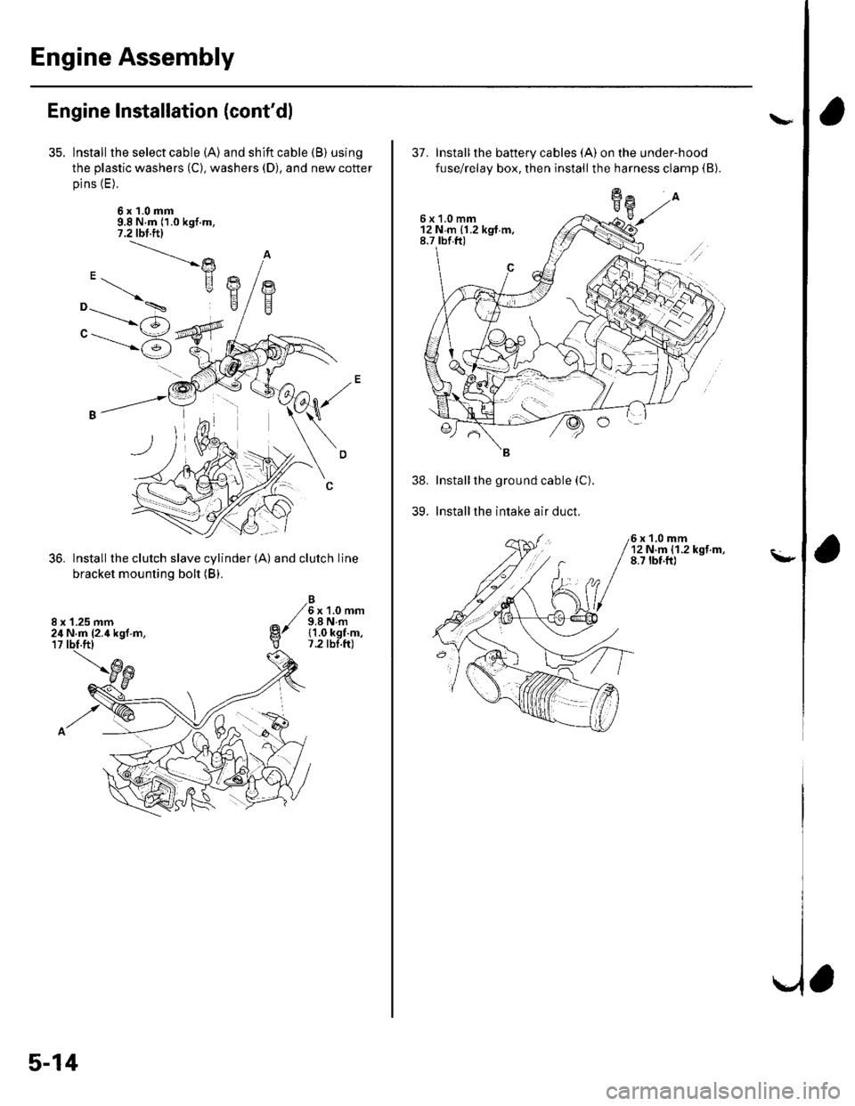
Install the select cable (A) and shift cable (B) using
the plastic washers (C), washers (D), and new cotter
pins (E).
6x1.0mm9.8 N.m (1.0 kgf.m,7.2 tbl.ftl
Install the clutch slave cylinder (A) and clutch line
bracket mounting bolt (B).
6x1.0mm9.8 N.m{1.0 kgf.m,7.2 tbt.ft)
"-.----->)
"------'6
8 x '1.25 mm24 N.m (2.4 kgl.m,
5-14
37. Installthe battery cables (A) on the under-hood
fuse/relay box, then install the harness clamp (B).
Installthe ground cable (C).
Installthe intake air duct.
6x1.0mm12Nm{1.2kgf.m,8.7 tbf.ft)
39.
\"
\-
a
6x1.0mm12Nm{1.2kgt.m,8.7 rbf.ft)