engine HONDA CIVIC 2002 7.G Service Manual
[x] Cancel search | Manufacturer: HONDA, Model Year: 2002, Model line: CIVIC, Model: HONDA CIVIC 2002 7.GPages: 1139, PDF Size: 28.19 MB
Page 95 of 1139
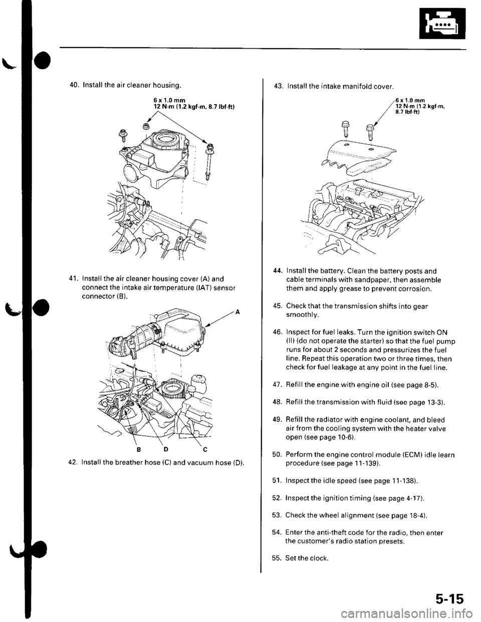
40. Install the air cleaner housinq.
6x1.0mm12 N m (1.2 kgf.m,8.7 lbt.ft)
Install the air cleaner housing cover (A) and
connect the intake air temperature (lAT) sensor
connector (B),
42. Installthe breather hose (C) and vacuum hose 1D).
41.
43. Installthe intake manifold cover.
6x1.0mm12Nm11.2kgf.m.8.7 tbf.ft)
Installthe battery. Clean the battery posts and
cable terminals with sandpaper, then assemble
them and apply grease to prevent corrosion.
Check that the transmission shifts into gear
smoothly.
Inspect for fuel leaks. Turn the ignition switch ON(ll) {do not operate the starter) so that the fuel pump
runs for about 2 seconds and pressurizes the fuel
line. Repeat this operation two or three times, then
check for fuel leakage at any point in the fuel line.
Refillthe engine with engine oil (see page 8-5).
Refill the transmission with fluid (see page 13-3).
Refill the radiator with engine coolant, and bleed
air from the cooling system with the heater valve
open (see page 10-6).
Perform the engine control module (ECM) idle learnprocedure (see page 11-139).
Inspect the idle speed (see page 1 1-138).
Inspect the ignition timing (see page 4-17).
Check the wheel alignment {see page 18-4).
Enter the anti-theft code for the radio, then enter
the customer's radio station presets.
Set the clock.
YE
44.
41.
]tE
46.
48.
49.
52.
53.
54.
50.
51.
55.
5-15
Page 96 of 1139
\
Engine Mechanical
Cylinder Head
Special Tools
Comoonent Location Index
Engine Compression Inspection
VTEC Rocker Arm Test ........... ............ 6-7
VTC Actuator Inspection .................... 6-8
Valve Clearance Adjustment ............. 6-9
Crankshaft Pulley Removal and Installation .............. 6-11
Cam Chain Removal ........................... 6-12
Cam Chain Installation ....................... 6-15
Auto-Tensioner Removal/1nsta11ation ......................... 6-19
Chain Case Oil Seal Installation ........ 6-21
Cyf inder Head Cover Removal .......... 6-22
Cylinder Head Removal ..................... 6-23
WC Actuator. Exhaust Camshaft Sorocket
Repf acement .........6-24
Cylinder Head Inspection for Warpage ...................... 6-25
Rocker Arm Assembly Removal ................................. 6-26
Rocker Arms and Shafts
Disassembly/Reassembly .............. 6-27
Rocker Arms and Shafts Inspection ............................ 6-28
Camshaft Inspection .......................... 6-29
Valves, Springs, and Valve Seals Removal ................ 6-31
Valve Insoection ...................... ........... 6-32
Valve Stem-to-Guide Clearance Insoection ............... 6-32
Valve Guide Reolacement ................. 6-33
Valve Seat Reconditioning ................ 6-35
Valves, Springs, and Valve Seals Installation ............ 6-37
Rocker Arm Assemblv Installation .... 6-38
Cvlinder Head Installation ........................................... 6-39
Cylinder Head Cover Installation ...... 6-41
6-2
6-3
b-t'
Page 101 of 1139
Cylinder Head
Engine Compression Inspection
1. Warm up the engine to normal operating
temperature (cooling fan comes on).
2. Turn the ignition switch OFF.
3. Remove the intake manifold cover (see step 1 onpage 6-22).
4, Disconnect all four injector connectors.
5. Start the engine, and let it run until it stalls.
6. Remove the iour ignition coils (see page 4-18).
7. Remove the four spark plugs.
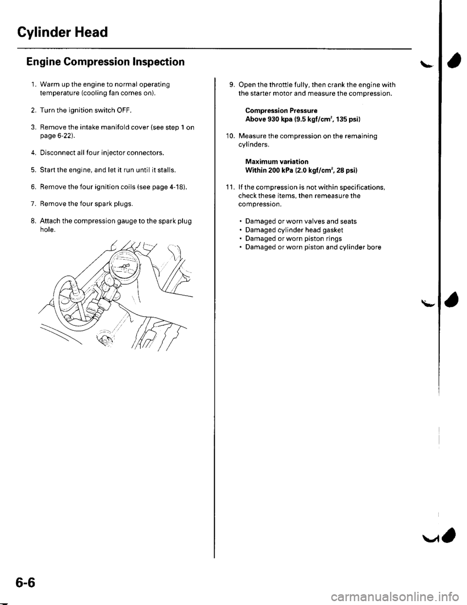
8. Attach the compression gauge to the spark plug
note.
6-6
V,
\
9.
10.
Open the throttle fully, then crank the engine with
the starter motor and measure the compression.
Compression Pressure
Above 930 kpa (9.5 kgf/cm', 135 psi)
Measure the compression on the remaining
cylinders,
Maximum vadation
Within 200 kPa (2.0 kgf/cm', 28 psi)
lf the compression is not within specifications,
check these items, then remeasure the
compressron.
. Damaged orworn valves and seats. Damaged cylinder head gasket. Damaged or worn piston rings. Damaged orworn piston and cylinder bore
11.
\-
Page 108 of 1139
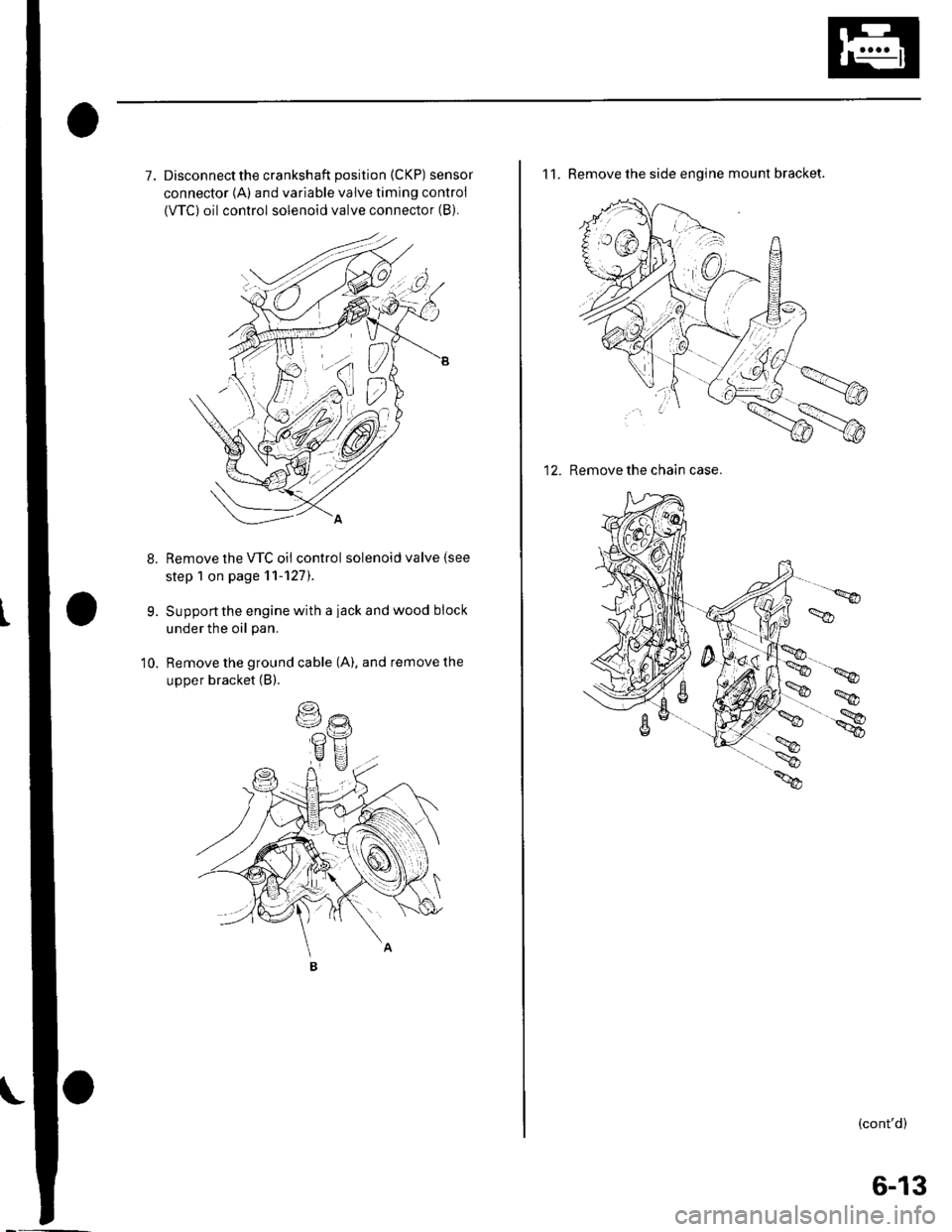
7. Disconnectthe crankshaft position (CKP) sensor
connector {A) and variable valve timing control
{VTC) oil control solenoid valve connector (B).
Remove the VTC oil control solenoid valve (see
step 1 on page 11-127).
Support the engine with a iack and wood block
under the oil pan.
Remove the ground cable (A). and remove the
upper bracket (B).
9.
10.
11. Remove the side engine mount bracket.
12. Remove the chain case.
(cont'd)
6-13
Page 113 of 1139
Gylinder Head
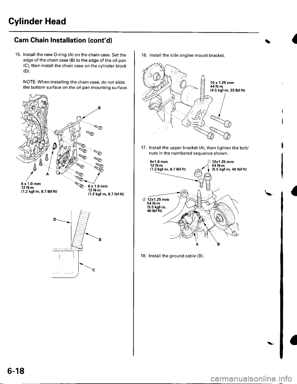
Cam Chain Installation (cont'd)
'15. Install the new O-ring (A) on the chain case. Set the
edge of the chain case (B) to the edge of the oil pan(C), then install the chain case on the cvlinder block(D).
NOTE: When installing the chain case, do not slide
the bottom surface on the oil pan mounting surface.
',.9
6x1.0mm12 N.m(1.2 kgt.m.8.7 lbf.ft)
6x1.0mm12Nm(1.2 kgf.m,8.7 lbf.ft)
6-18
\-
{t
16. lnstallthe side engine mount.bracket.
17. Installthe upper bracket (A), then tighten the bolv
nuts in the numbered seouence shown.
6x1.0 mm12 N.m{1.2 kgl m, 8.7 lbf ft}
12x1.25 mm54 N.m(5.5 kgt m, 40 lbf.ft)
I\a
18. Install the ground cable (B).
rbf.ft)
Page 118 of 1139
Gylinder Head Removal
NOTE:. Use fender covers to avoid damaging painted
surfaces.
To avoid damage, unplug the wiring connectors
carefully whlle holding the connector portion.
To avoid damaging the cylinder head, wait until the
engine coolant temperature drops below 100'F (38"C)
betore loosening the cylinder head bolts.
Mark all wiring and hoses to avoid misconnection.
Also, be sure that they do not contact other wiring or
hoses, or interfere with other parts.
'1.
2.
3.
Drain the engine coolant (see page 10-6).
Remove the drive belt (see page 4-26).
Remove the intake manifold {see page 9-3).
Remove the air cleaner housing (see step 7 on page
5-2t.
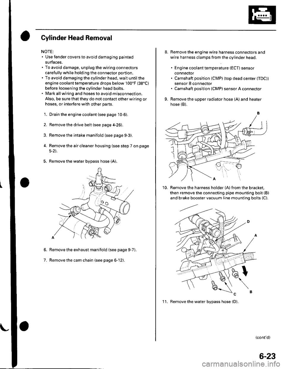
5. Remove the water bypass hose (A).
Remove the exhaust manifold (see page 9-7
Remove the cam chain (see page 6-12).
6.
7.
).
8. Remove the engine wire harness connectors and
wire harness clamps from the cylinder head.
. Engine coolant temperature (ECT) sensor
conneclor. Camshaft position (Cl\4P) (top dead center (TDC))
sensor B connector. Camshaft posilion (CMP) sensor A connector
9. Remove the upper radiator hose (A) and heater
hose (B).
'10. Remove the harness holder (A)from the bracket,
then remove the connecting pipe mounting boh {B)
and brake booster vacuum line mounting bolts {C).
(cont'd)
1 1. Remove the water bvpass hose (D).
6-23
Page 120 of 1139
Installation:
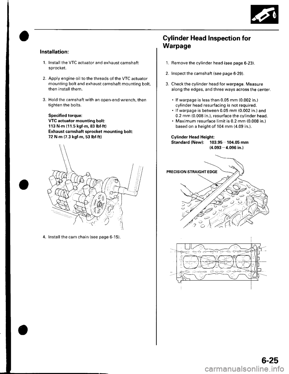
1. Install the VTC actuator and exhaust camshaft
sprocket.
2. Apply engine oil to the th reads of the VTC actuato r
mounting bolt and exhaust camshaft mounting bolt,
then install them.
3. Hold the camshaft with an open-end wrench, then
tighten the bolts.
Specified torque:
VTC actuator mounting bolt:
113 N.m (11.5 kgl.m,83 lbl.ft)
Exhaust camshaft sprocket mounting bolt:
72 N m (7.3 kgf.m, 53 lbf.ft)
4. Install the cam chain {see page 6-15).
1,
Cylinder Head Inspection for
Warpage
Remove the cylinder head {see page 6-23).
Inspect the camshaft (see page 6-29).
Check the cylinder head for warpage. Measure
along the edges, and three ways across the center.
. lf warpage is less than 0.05 mm (0.002 in.)
cylinder head resurfacing is not required.. lf warpage is between 0.05 mm (0.002 in.) and
0.2 mm (0.008 in.), resurface the cylinder head.. Maximum resurface limit is 0.2 mm (0.008 in,)
based on a height of 104 mm (4.09 in.).
Cylinder Head Height;
Standard {New}: 103.95 104.05 mm
{4.093 4.096 in.}
6-25
Page 129 of 1139
Cylinder Head
Valve Guide Replacement (cont'dl
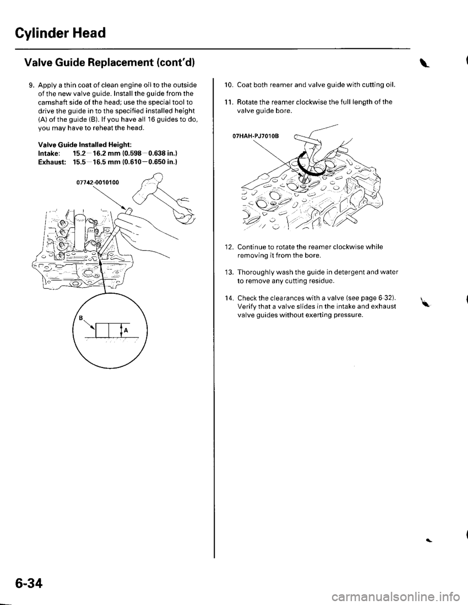
Apply a thin coat of clean engine oil to the outside
of the new valve guide. Install the guide from the
camshaft side of the head; use the special tool to
drive the guide in to the specified installed height
(A) o{the guide (B). lf you have all 16 guidesto do,
you may have to reheat the head.
Valve Guide Installed Height:
Intake: 15.2 16.2 mm (0.598-0.638 in.)
Exhaust: 15.5 16.5 mm (0.610-0.650 in.)
6-34
\
10.Coat both reamer and valve guide with cutting oil.
Rotate the reamer clockwise the full length of the
valve guide bore.
O7HAH.PJ7O1OB
Continue to rotate the reamer clockwise while
removing it from the bore.
Thoroughly wash the guide in detergent and water
to remove any cutting residue.
Check the clearances with a valve (see page 6 32).
Verify that a valve slides in the intake and exhaust
valve guides without exening pressure.
11.
14.
'-\
Page 132 of 1139
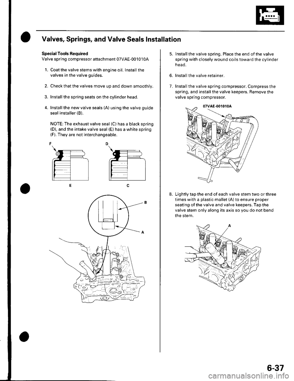
Valves, Springs, and Valve Seals Installation
Special Tools Required
Valve spring compressor attachment 07VAE-00101 0A
1. Coat the valve stems with engine oil. lnstall the
valves in the valve guides.
2. Check that the valves move up and down smoothly.
Installthe spring seats on the cylinder head.
Install the new valve seals (A) using the valve guide
seal installer (B).
NOTE: The exhaust valve seal (C) has a black spring(D), and the intake valve seal (E) has a white spring(F). They are not interchangeable.
6.
lnstallthe valve spring. Place the end ofthe valve
spring with closely wound coils toward the cylinder
n eao.
Install the valve retainer.
Installthe valve spring compressor, Compress the
spring, and install the valve keepers. Remove the
valve spring compressor.
Lightly tap the end of each valve stem two or three
times with a plastic mallet (A) to ensure proper
seating of the valve and valve keepers. Tap the
valve stem only along its axis so you do not bend
the stem.
7.
6-37
Page 135 of 1139
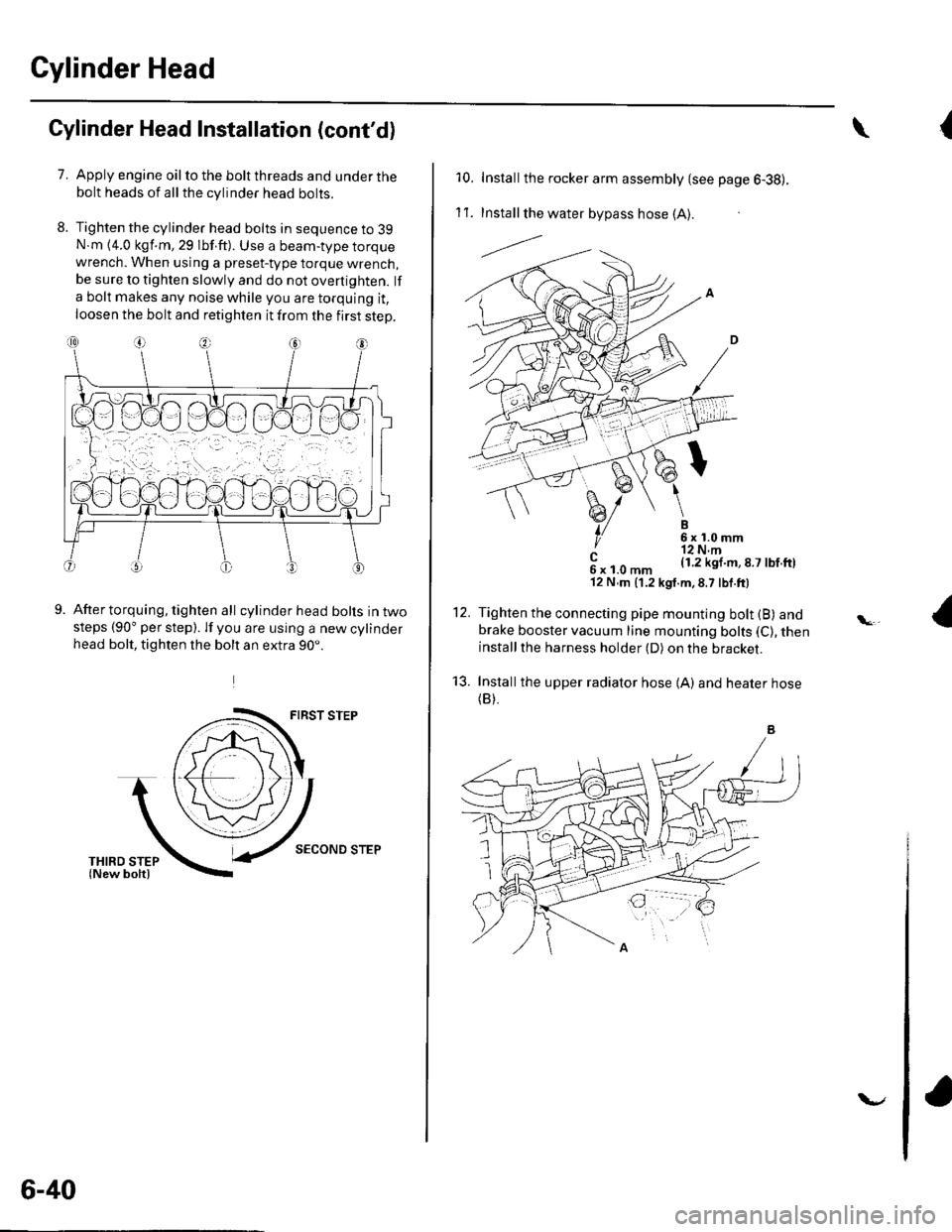
Cylinder Head
8.
Cylinder Head lnstallation (cont'd)
7.Apply engine oil to the bolt threads and under thebolt heads of all the cylinder head bolts.
Tighten the cylinder head bolts in sequence to 39N.m {4.0 kgf.m, 29 lbf.ft). Use a beam-type torquewrench. When using a preset-type torque wrench,be sure to tighten slowly and do not overtighten. lf
a bolt makes any noise while you are torquing it,
loosen the bolt and retighten it from the first step.
9.After torquing, tighten all cylinder head bolts in twosteps (90" per step). lf you are using a new cylinderhead bolt, tighten the bolt an extra 90..
FIRST STEP
SECOND STEP
6-40
v
{\
10. Installthe rocker arm assembly {see page 6-38).
1't .Install the water bypass hose (A).
---l.-.
B6x1.0mm'r2 N.m(1.2 kgl.m,8.7 lbf.ftl
12.
't3.
c6xl.0mm'12 N,m (1.2 kgt.m,8.7 lbf.ft)
Tighten the connecting pipe mounting bolt (B) andbrake booster vacuum line mounting bolts (C), theninstallthe harness holder (D) on the bracket.
Installthe upper radiator hose {A) and heater hose(B).