engine HONDA CIVIC 2002 7.G Manual Online
[x] Cancel search | Manufacturer: HONDA, Model Year: 2002, Model line: CIVIC, Model: HONDA CIVIC 2002 7.GPages: 1139, PDF Size: 28.19 MB
Page 174 of 1139
Engine Lubrication
OilPump Overhaul
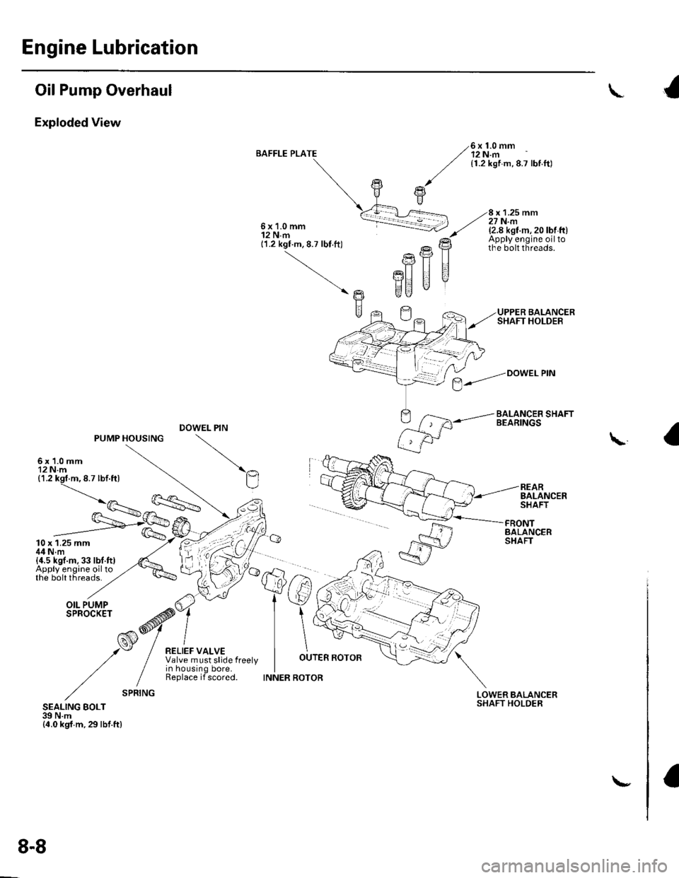
Exploded View
BAFFLE PLATE6x1.0mm12 N.m{1.2 kgf m,8.7 lbf.ft)
x 1.25 mm27 N.m6x1.0mm12 N.m11.2 kgf.m, 8.7 lbt ft)
(2.8 kst m, 20 lbt ft)Apply engine oiltothe bolt threads.
UPPER BALANCERSHAFT HOLDER
BALANCER SHAFTBEARINGS
Ptr
PU II
EU "
DOWEL PIN
REARBALANCERSHAFT
\
- /=.---'n
fs/
tw
FRONTBALANCERSHAFT
LOWERSHAFTBALANCERHOLDERSEALING BOLT39 N.m{4.0 kgf.m,29lbf.ftl
$--."Dowetem
8-8
\-
Page 176 of 1139
Engine Lubrication
Oil Pump Overhaul {cont'dl
Oil Pump Inspection
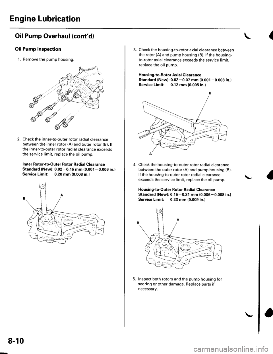
1. Remove the pump housing.
Check the inner-to-outer rotor radial clearance
between the inner rotor (A) and outer rotor {B). lf
the inner-to-outer rotor radial clearance exceeds
the service limit, replace the oil pump.
Inner Rotor-to-Outer Botor Radial Clearance
Standard {New): 0.02 0.16 mm (0.001 -0.006 in.)
Service Limit: 0.20 mm (0.008 in.,
1'[1e-\1.-,-2
1 'a - :.: ,-'r'
8-10
\-
{
4.
3. Check th e h ousing-to-roto r axia I clearance between
the rotor (A) and pump housing (B). lf the housing-
to-rotor axial clearance exceeds the service limit.
replace the oil pump.
Housing"to-Rotor Axial Clearance
Standard (New): 0.02 0.07 mm (0.001 -0.003 in.l
Service Limit: 0.12 mm (0.005 in.l
Check the housing-to-outer rotor radial clearance
between the outer rotor (A) and pump housing (B).
lf the housing-to-outer rotor radial clearance
exceeds the service limit, replace the oil pump.
Housing-to-Outer Rotor Radial Clearance
Standard lNewl: 0.15 0.21 mm (0.006-0.008 in.l
Service Limit; 0.23 mm (0.009 in.)
Inspect both rotors and the pump housing for
scoring or other damage. Replace parts if
necessary.
\,
Page 178 of 1139
Engine Lubrication
Oil Pump Overhaul (cont'dl
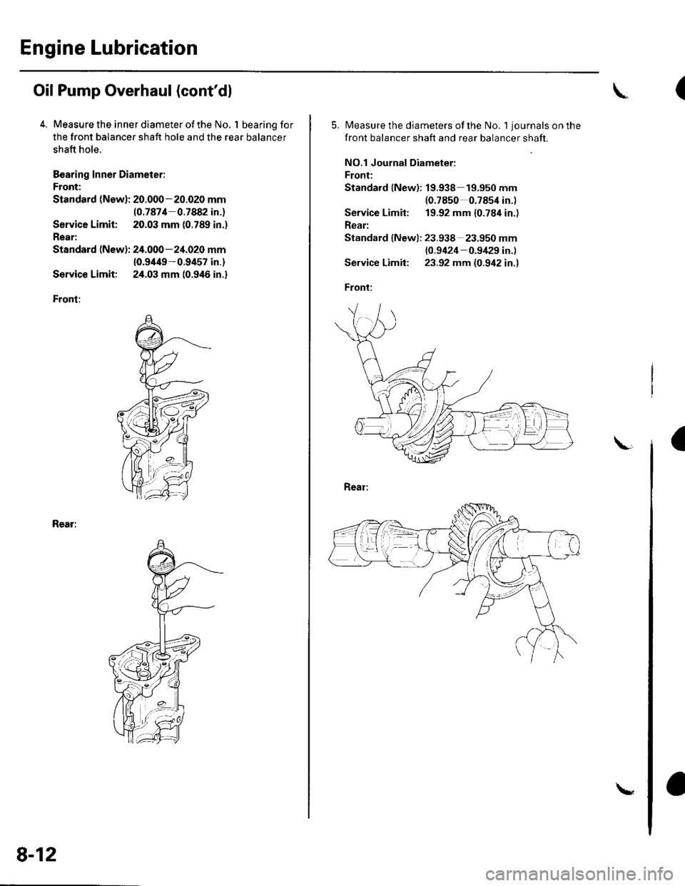
4. Measure the inner diameter of the No. 1 bearing for
the front balancer shaft hole and the rear balancer
shaft hole.
Bearing Inner Diameier:
Front:
Standard (New): 20.000-20.020 mm(0.7874 0.7882 in.)
Service Limit; 20.03 mm (0.789 in.)
Rear:
Standard (New): 24.000-24.020 mm
10.9/t49-0.9457 in.)
Service Limit: 24.03 mm (0.946 in.)
Front:
Rear:
8-12
\
(
5.Measure the diameters of the No. 1 journals on the
front balancer shaft and rear balancer shaft.
NO.1 Journal Diameter:
Front:
Standard lNew): 19.938 19.950 mm(0.7850 0.7854 in.)
Service Limit: 19.92 mm {0.784 in.)
Rear:
Standard lNewl: 23.938 23.950 mm
{0.9424-0.9/129 in.)
Service Limit: 23.92 mm (0.942 in.)
Front:
a
Page 179 of 1139
8.
9.
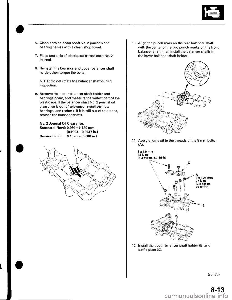
6. Clean both balancer shaft No. 2 journals and
bearing halves with a clean shop towel.
7. Place one strip of plastigage across each No.2journal.
Reinstall the bearings and upper balancer shaft
holder, then torque the bolts.
NOTE; Do not rotate the balancer shaft durinq
insDection.
Remove the uooer balancer shaft holder and
bearings again, and measure the widest part of the
plastigage. lf the balancer shaft No. 2 journal oil
clearance is out-of-tolerance. install the new
bearings, and recheck. lf it is still out-of-tolerance,
replace the balancer shafts.
No. 2 Journal Oil Clearance:
Standard lNewl; 0.060 0.120 mm
Service Limit:
(0.0024 0.0047 in.l
0.15 mm {0.006 in.)
10. Align the punch mark on the rear balancer shaft
with the center of the two punch marks on the front
balancer shaft, then install'the balancer shafts in
the lower balancer shaft holder
Apply engine oil to the threads of the 8 mm bolts(A).
6x1.0mm'12 N.m(1.2 kgt.m, 8.7 lbt ft)
11.
Installthe upper balancer shaft holder (B) and
bafile plate (C).
(cont'd)
12.
8-13
Page 180 of 1139
Engine Lubrication
Oil Pump Overhaul (cont'd)
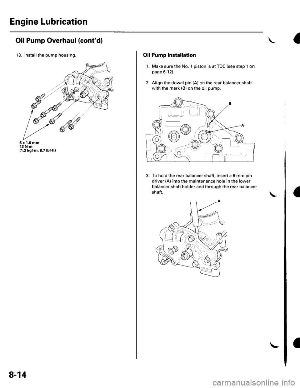
13. lnstallthe pump housing.
6x1,0mm12 N.m(1.2 kgt.m,8.7 lbf.ft)
8-14
!
Oil Pump Installation
1. Make sure the No. 1 piston is at TDC (see step 1 on
page 6-12).
2. Align the dowel pin{A} on the rear balancer shaft
with the mark (B) on the oil pump.
To hold the rear balancer shaft, insert a 6 mm pin
driver {A) into the maintenance hole in the lower
balancer shaft holder and through the rear balancer
shaft.\,-
9%ttrc
+:.:4.4 / t \
o/.-lY\
:aa:'
-rr
dv
f,o-;
Page 181 of 1139
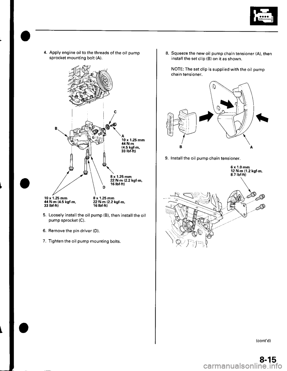
4. Apply engine oil to the threads of the oil pump
sprocket mounting bolt (A).
A10 x 1.25 mm{4 N.m(a.5 kg{ m,33 rbf.ftl
10x 1.25 mm,l,t N.m {4.5 kgf.m,33 tbt.ftl
5. Loosely installthe oil
pump sprocket (C).
8 x 1,25 mm22N m l2.2kot m.r6 tbt.fti
pump (B), then installthe oil
7.
Remove the pin driver (D).
Tighten lhe oil pump mounting bolts.
I
8-15
8. Squeeze the new oil pump chain tensioner (A), theninstall the set clip (B) on it as shown.
NOTE: The set clip is supplied with the oil pump
chain tensioner.
9. Install the oil Dum D cha in tensioner.
6x1.0mm12 N.m (1.2 kgf.m,8.7 rbf.ft)
IB
(cont'd)
Page 182 of 1139
Engine Lubrication
Oil Pump Overhaul (cont'dl
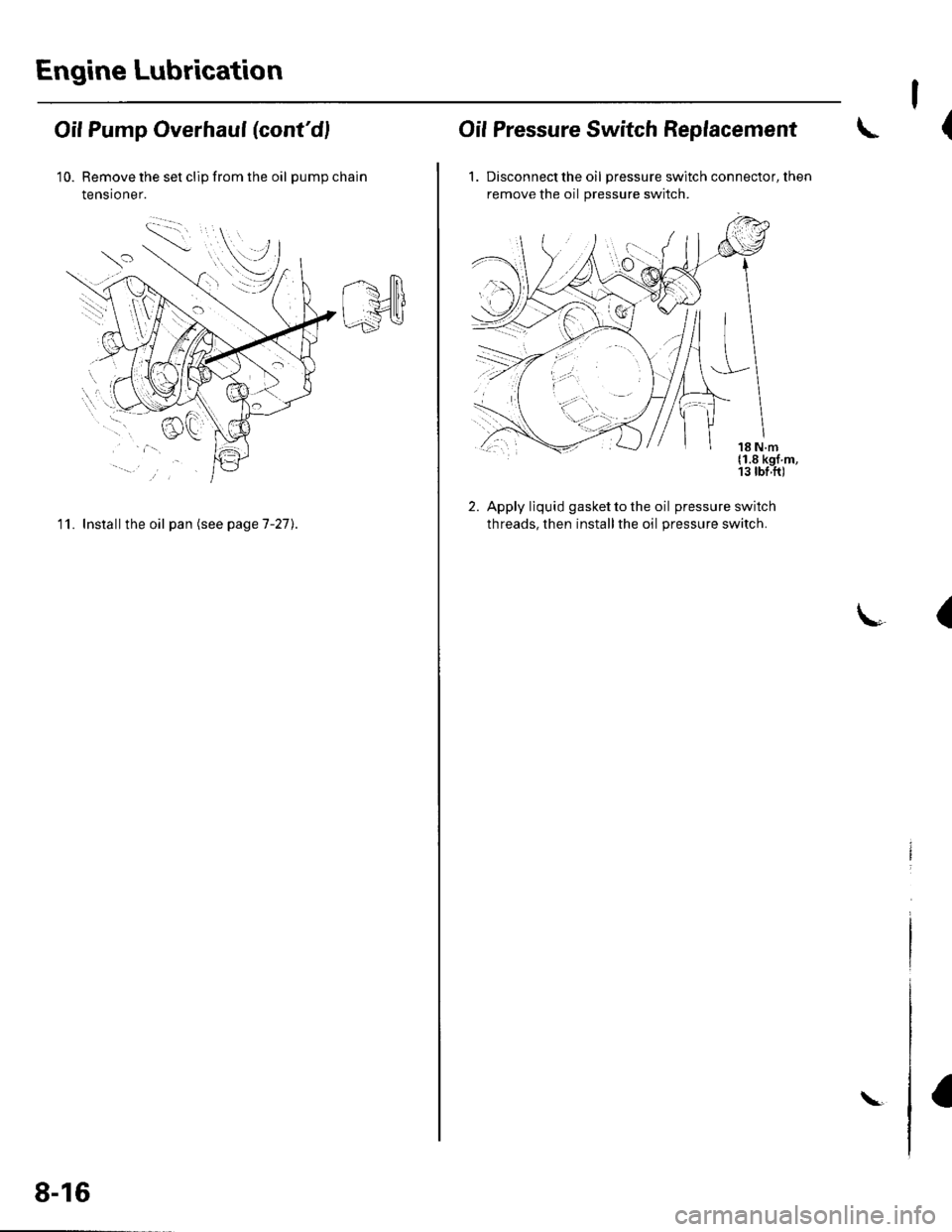
10. Remove the set clip from the oil pumpchain
tensioner.
11. Install the oil pan (see pageT-27).
8-16
\
I
(Oif Pressure Switch Replacement
1. Discon nect the oil pressure switch connector, then
remove the oil pressure switch.
2. Apply liquid gasket to the oil pressure switch
threads, then installthe oil pressure switch.
(
Page 183 of 1139
Engine Mechanical
Intake Manifold and Exhaust System
lntake Manifold Removal and Installation ................. 9-2
Exhaust Manifold Removal and Installation .............. 9-7
Exhaust Pipe and Muffler Replacement ..................... 9-8
r
r-!i!1
Page 186 of 1139
Intake Manifold and Exhaust System
Intake Manifold Removal and Installation (cont'dl
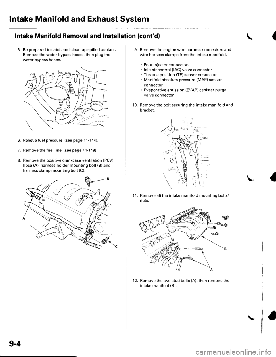
5. Be prepared to catch and clean up spilled coolant.
Remove the water bypass hoses, then plug the
water bypass hoses.
6. Relievefuel pressure (see page 11-'144).
7. Remove the fuel line (seepagell-149).
8. Remove the positive crankcase ventilation (PCV)
hose (A), harness holder mounting bolt (B) and
harness clamp mounting bolt (C).
9-4
\-
(
9.Remove the engine wire harness connectors and
wire harness clamps from the intake manifold.
. Four injector connectors. ldle air control (lAC) valve connector. Throttle position (TP) sensor connector. fvlanifold absolute pressure {lvlAP) sensor
connector. Evaporative emission (EVAP)canister purge
valve connector
Remove the bolt securing the intake manifold and
bracket.
'1 0.
11.Remove allthe intake manifold mounting bolts/
nuts.
Remove the two stud bolts (A), then remove the
intake manifold (B).
1'>
Page 188 of 1139
lntake Manifold and Exhaust System
Intake Manifold Removal and Installation (cont'd)
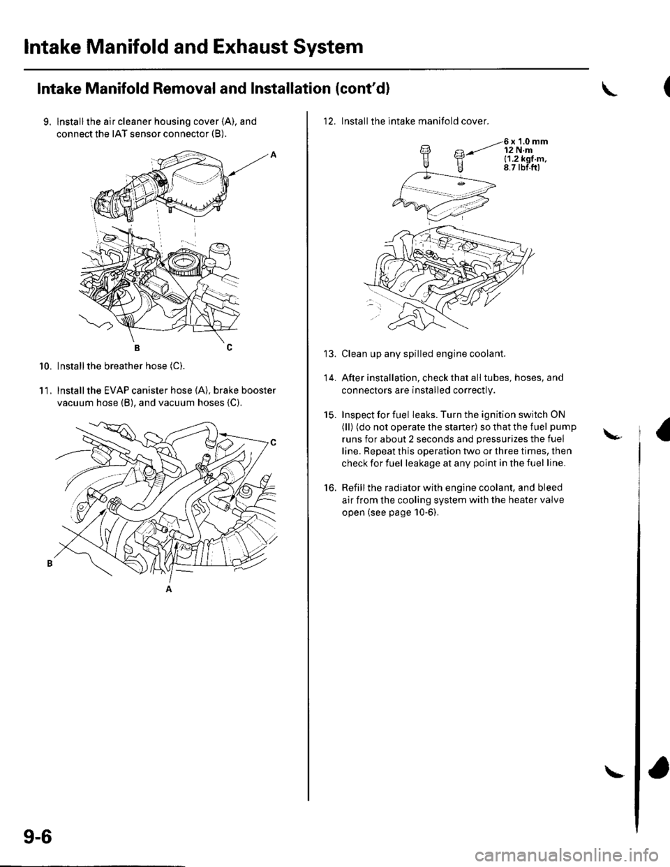
9. lnstallthe air cleaner housing cover (A), and
connect the IAT sensor connector (B).
BC
Installthe breather hose (C).
lnstallthe EVAP canister hose (A), brake booster
vacuum hose (B), and vacuum hoses {C).
10.
11.
9-6
\
12. Installthe intake manifold cover.
6x1.0mm12 N.ml.1.2k91.m,8.7 tbf.ftl
Clean up any spilled engine coolant.
After installation, check that all tubes, hoses, and
connectors are installed correctly.
Inspect for fuel leaks. Turn the ignition switch ON
(ll) (do not operate the starter) so that the fuel pump
runs for about 2 seconds and pressurizes the fuel
line. Repeat this operation two or three times, then
check for fuel leakage at any point in the fuel line.
Refill the radiator with engine coolant, and bleed
air from the cooling system with the heater valve
open (see page 10-6).
to.
\-