HONDA CIVIC 2003 7.G Workshop Manual
CIVIC 2003 7.G
HONDA
HONDA
https://www.carmanualsonline.info/img/13/5744/w960_5744-0.png
HONDA CIVIC 2003 7.G Workshop Manual
Trending: hood release, radiator replace, Window, checking oil, Brake caliper, windshield wiper, key fob battery
Page 391 of 1139
EVAP System
DTC Troubleshooting (cont'dl
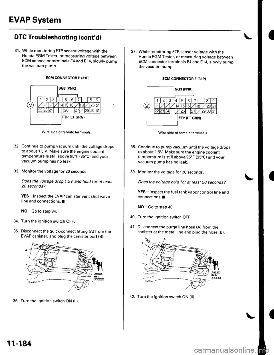
31. While monitoring FTP sensor voltage with theHonda PGM Tester, or measuring voltage betweenECM connector terminals E4 and E14, slowly pump
the vacuum oumD.
ECM CONNECTOR E 13lPI
Wire side ot female terminals
32. Continue to pump vacuum until the voltage drops
to about 1.5 V. Make sure the engine coolant
temperature is still above 95'F 135.C) and your
vacuum pump has no leak.
33. Monitor the voltage for 20 seconds.
Does the voltage drop 1.5V and hold for at least
20 seconds?
YES Inspect the EVAP canister vent shut valve
line and connections.l
NO-Go to step 34.
34. Turn the ignition switch OFF.
35. Discon nect the quick-con nect fitting (A) fromthe
EVAP canister, and plug the canister port {B).
36. Turn the ignition switch ON (ll).
11-184
42. Turn the ignition switch ON (ll).
I
38.
39.
37. While monitoring FTP sensor voltage with theHonda PGM Tester, or measuring voltage betweenECM connector terminals E4 and E 14, slowly pump
the vacuum pump.
ECM CONNECTOR E {31PI
Wire side of lemale terminals
Continue to pump vacuum until the voltage drops
to about 1.5V. Make sure the engine coolant
temperature is still above 95"F (35"C) and your
vacuum pump has no leak.
Monitor the voltage for 20 seconds
Does the voltage hold for at least 20 seconds?
YES Inspecl the fuel tank vapor control lineand
connections.I
NO Go to step 40.
Turn the ignition switch OFF.
Disconnect the purge line hose {A) from the
canister at the metal line and plug the hose (B).
40.
41.
Page 392 of 1139
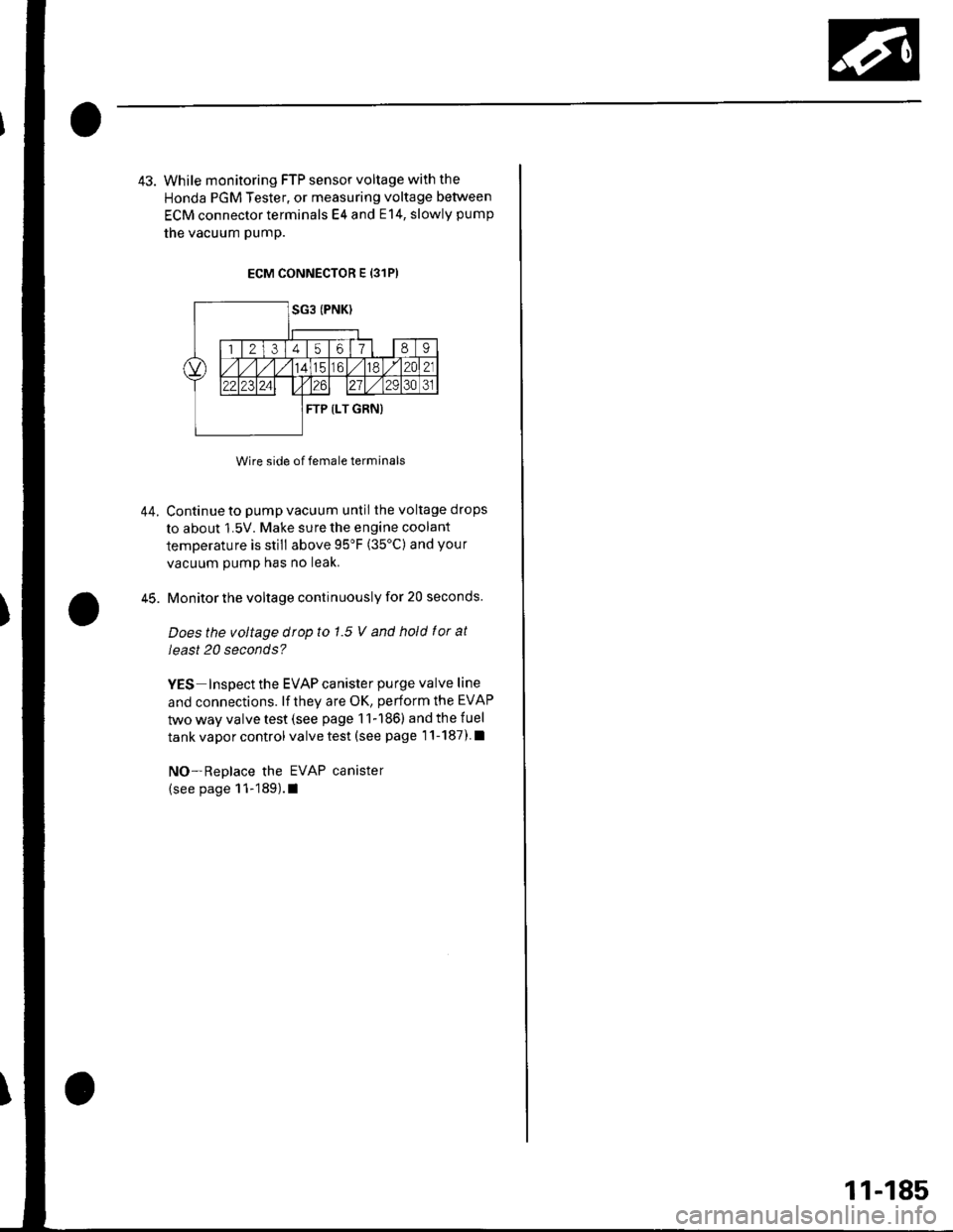
43. While monitoring FTP sensor voltage with the
Honda PGM Tester, or measuring voltage between
ECM connector terminals E4 and E14, slowly pump
the vacuum pump.
ECM CONNECTOR E {31P)
Wire side of female terminals
Continue to pump vacuum until the voltage drops
to about 1.5V. Make sure the engine coolant
temperature is still above 95'F (35'C) and your
vacuum pump has no leak.
Monitor the voltage continuously for 20 seconds.
Does the voltage drop to 1.5 V and hold f or at
least 20 seconds?
YES Inspect the EVAP canister purge valve line
and connections. lf they are OK, perform the EVAP
two way valve test (see page 11-186) and the fuel
tank vapor control valve test (see page 1'l-187) l
NO-Replace the EVAP canister
(see page 11-189).1
44.
45.
11-185
Page 393 of 1139
EVAP System
EVAP Two Way Valve Test
Special Tools Required. Vacuum pump/Gauge,0-30 in. Hg
A973X-041-XXXXX. Vacuum/Pressure cauge.0-4 in. Hg 07JAZ-0010008
1. Remove the fuelfill cap.
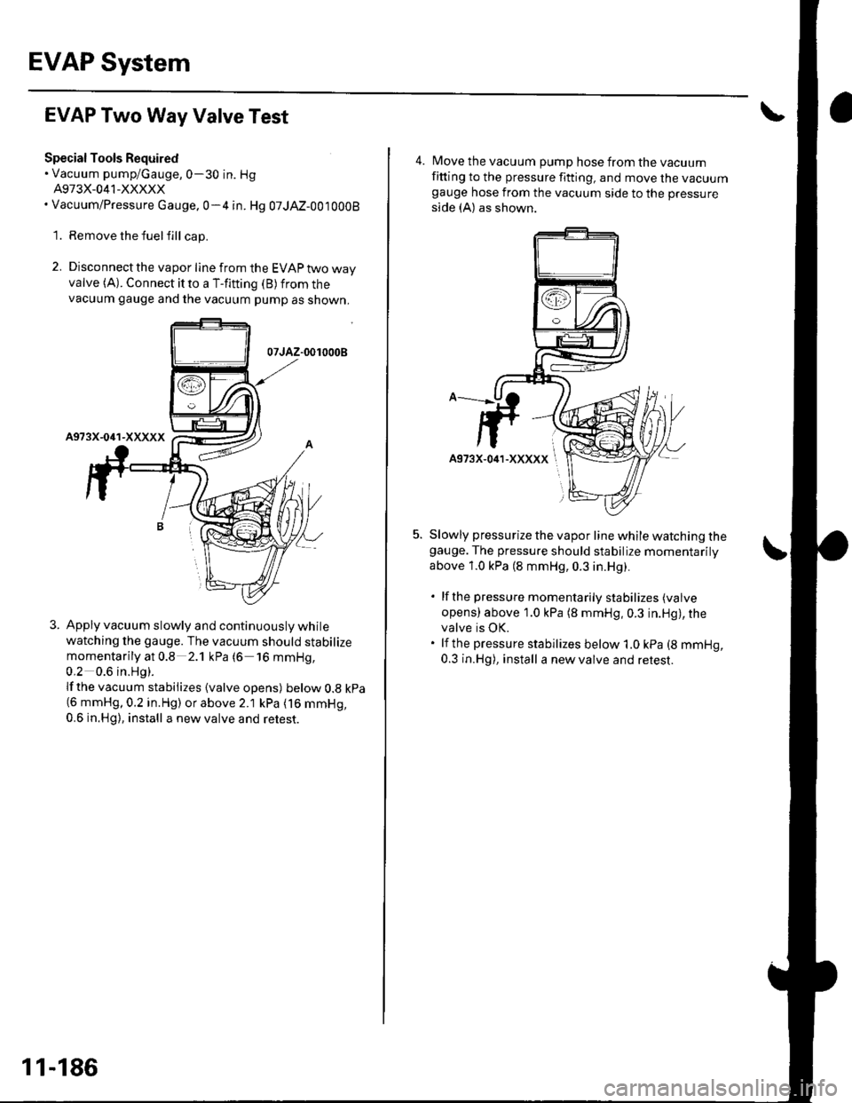
2. Disconnect the vapor line from the EVAP two wayvalve (A). Connect it to a T-fitting (B) from thevacuum gauge and the vacuum pump as shown,
07JAZ-0010008
Apply vacuum slowly and continuously while
watching the gauge. The vacuum should stabilize
momentarily at 0.8 2.1 kPa (6 16 mmHg,
0,2 0.6 in.Hg).
lf the vacuum stabilizes {valve opens) below 0.8 kpa(6 mmHg,0.2 in.Hg) or above 2.1 kPa (16 mmHg,
0.6 in.Hg), install a new valve and retest.
11-186
4. Move the vacuum pump hose from the vacuumfitting to the pressure fitting, and move the vacuumgauge hose from the vacuum side to the pressure
side (A) as shown.
Slowly pressurize the vapor line while watching thegauge. The pressure should stabilize momentarilV
above 1.0 kPa (8 mmHg, 0.3 in.Hg).
. lfthe pressure momentarily stabilizes (valve
opens) above 1.0 kPa (8 mmHg,0.3 in.Hg), thevalve is OK.. lf the pressure stabilizes below 1.0 kPa (8 mmHg,
0.3 in.Hg), install a new valve and retest.
Page 394 of 1139
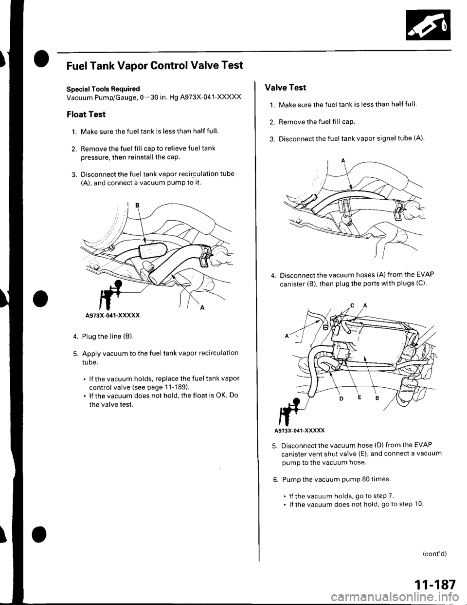
FuelTank Vapor Control Valve Test
Special Tools Required
Vacuum Pump/Gauge, 0-30 in. Hg A973X-041-XXXXX
Float Test
1. Make sure the fuel tank is less than half full.
2. Remove the fuel fill cap to relieve fuel tank
pressure, then reinstall the cap.
3. Disconnect the fuel tank vapor recirculation tube
{A), and connect a vacuum PumP to it.
Plug the line (B).
Apply vacuum to the fuel tank vapor recirculation
tuDe.
lf the vacuum holds, replace the fuel tank vapor
control valve (see page 11-189).
lf the vacuum does not hold, the float is OK. Do
the valve test.
5.
A973X-041-XXXXX
Valve Test
1. N4ake sure the fuel tank is less than half full
2. Remove the fuel fill cap.
3. Disconnect the fuel tank vapor signal tube (A).
Disconnect the vacuum hoses (A) from the EVAP
canister (B), then plug the ports with plugs (C)4.
A973X-O41-XXXXX
5. Disconnect the vacuum hose (D) from the EVAP
canister vent shut valve (E), and connect a vacuum
pump to the vacuum hose.
6. Pump the vacuum pump 80 times.
. lf the vacuum holds, goto steP 7.. lf the vacuum does no1 hold, go to step 10.
(cont'd)
11-187
Page 395 of 1139
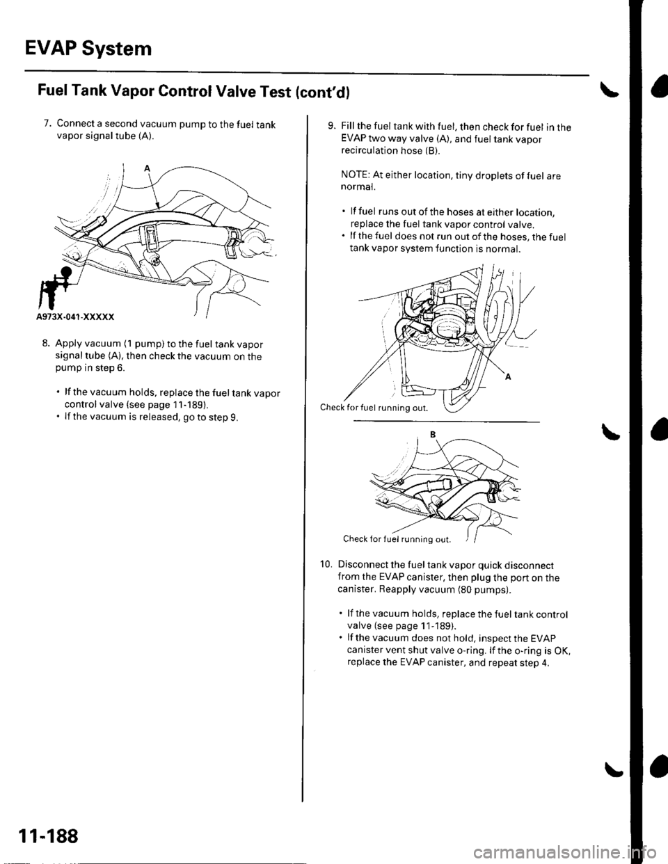
EVAP System
FuelTank Vapor ControlValve Test (cont'd)
7. Connect a second vacuum pump to the fuel tankvapor signaltube (A).
8. Apply vacuum (1 pump) to the fuel tank vaporsignal tube (A). then check the vacuum on thepump in step 6.
. lf the vacuum holds, replace the fueltank vapor
control valve {see page 11-189).. If the vacuum is released, goto step 9.
11-188
10.
Fill the fuel tank with fuel, then check for fuel in theEVAP two way valve (A), and fuel tank vaporrecirculation hose (B).
NOTE: At either location, tiny droplets of fuel arenormal.
. lf fuel runs out of th e hoses at either location,
replace the fuel tank vapor control valve..lfthefuel does not run out of the hoses, the fuel
tank vapor system function is normal.
Disconnect the fuel tank vapor quick disconnectfrom the EVAP canister, then plug lhe port on the
canister. Reapply vacuum (80 pumps).
. lf the vacuum holds, replace the fuel tank control
valve (see page 1 1-189).. lf the vacuum does not hold, insDect the EVAP
canister vent shut valve o-ring. lf the o-ring is OK,replace the EVAP canister, and repeat step 4.
Check for fuel rirnning out.
Check for fuel running out.
Page 396 of 1139
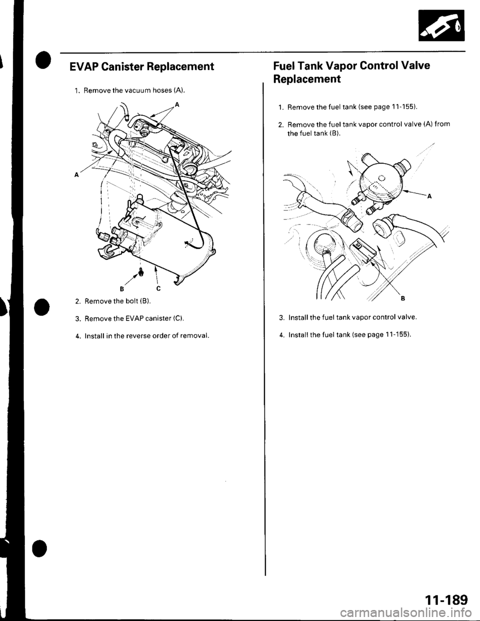
EVAP Canister Replacement
l. Remove the vacuum hoses (A).
2. Remove the boit (B).
3. Remove the EVAP canister (C).
4. Install in the reverse order of removal.
Fuel Tank Vapor Control Valve
Replacement
1. Remove the fuel tank(seepagell-155).
2. Remove the fueltank vapor control valve(A) from
the fuel tank (B).
Install the fuel tank vapor control valve.
Install the fuel tank (see page 1 'l -155).
3.
4,
11-189
Page 397 of 1139
Page 398 of 1139
Clutch
Special Tools ......... 12-2
Comoonent Location Index .......................,............. 12-3
Clutch Pedal, Clutch Pedal Position Switch, and
Clutch Interlock Switch Adiustment .................... 12-4
Cf utch Master Cylinder Rep|acement ..................... 12-5
Slave Cylinder Replacement .'........ 12-7
Clutch Replacement ................... ..... 12-9
Page 399 of 1139
a
a
l.
l_l
'l-r
o
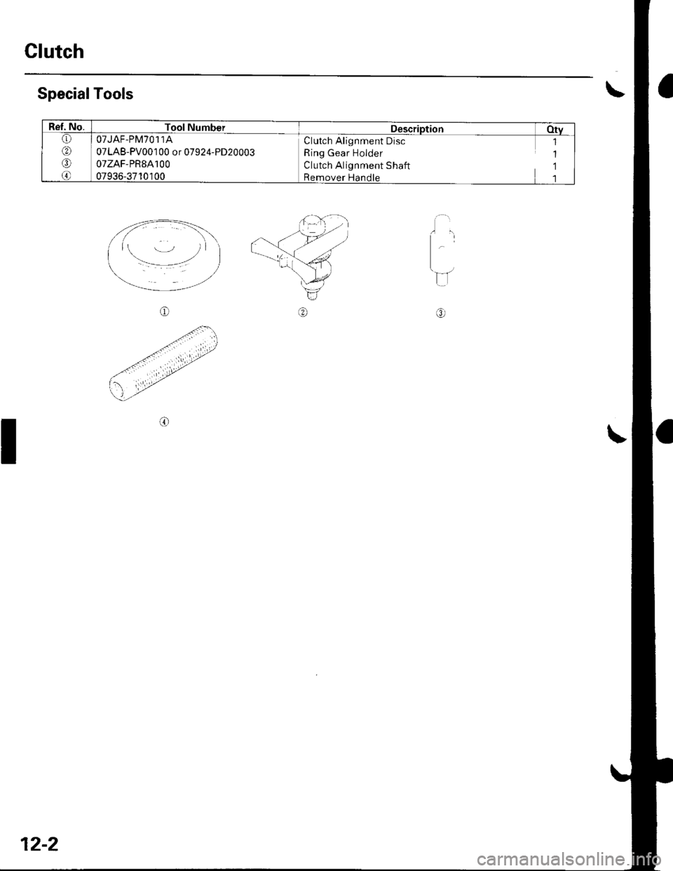
SpecialTools
o
.{\
.tt./
'\-'/
o
Clutch
I
12-2
Ref. No.Tool NumberDescription Oty(1,
@
o
@
OTJAF-PM7O11A
07LAB-PV001 00 or 07924-PD20003
07zAF-PR8A100
07936-3710100
,l
1
1
1
Clutch Alignment Disc
Ring Gear Holder
Clutch Alignment Shaft
Remover Handle
Page 400 of 1139
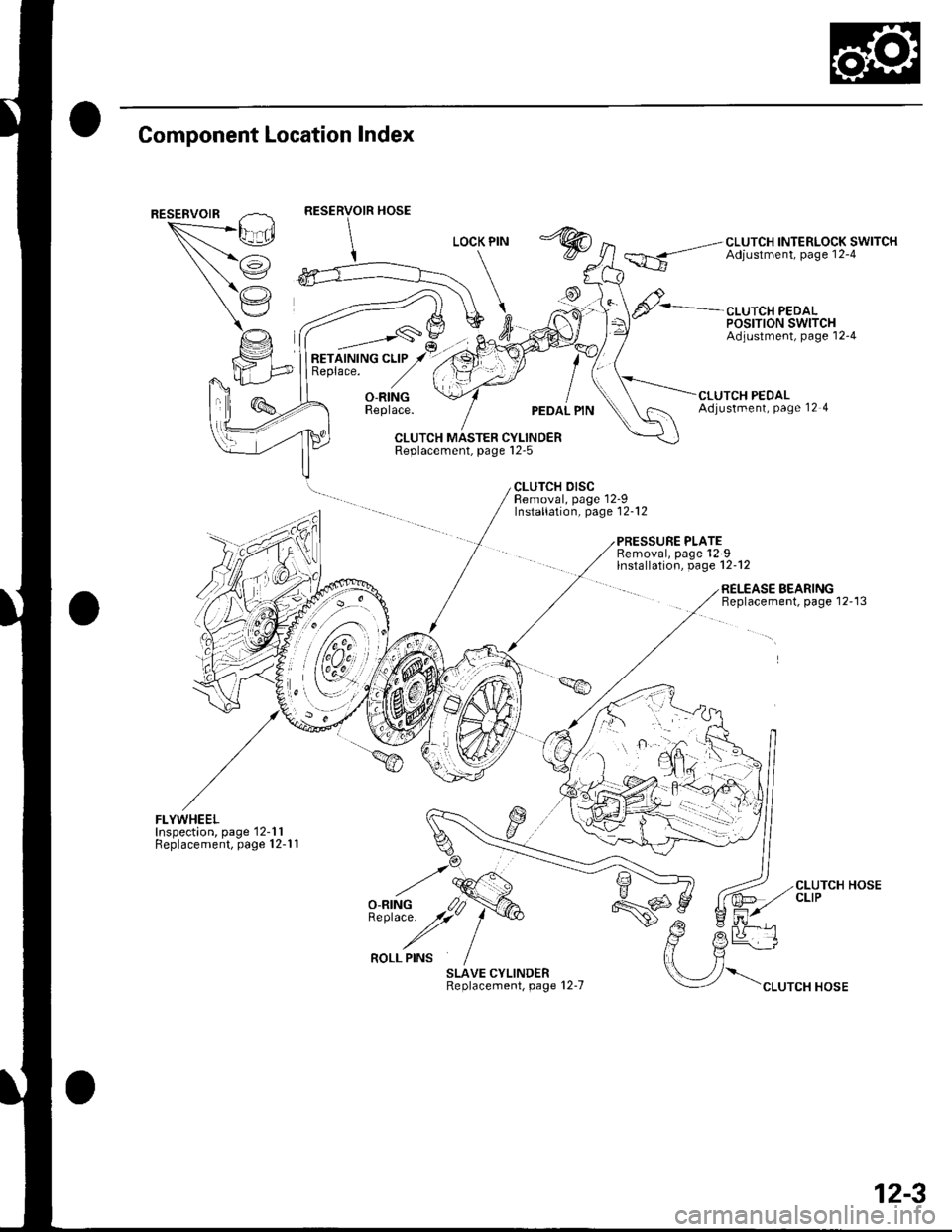
Component Location Index
""*--/\,L_.Ei
/i
(,'.'
CLUTCH INTERLOCK SWITCHAdjustment, page 12-4
CLUTCH PEDALPOSTTTON SWITCHAdjustment, page'12-4
RETAINING CLIPReplace.
_,___-,-s\
O-RINGReplace.UTCH PEDALAdjustment, Page 12 4
CLUTCH MASTER CYLINDERReplacement, page l2-5
CLUTCH DISCBemoval, page 12-9Installation, page'12-12
PRESSURE PLATERemoval, page'12-9lnstallation, page 12-12
FLYWHEELInspection, page'12-1 1Replacement, page 12-1 1
SLAVE CYLINDERReplacement, page 12-7
RELEASE BEARINGBeplacement, page 12-13
\".rr"*"o*
CLUTCH HOSECLIP
12-3
Trending: ignition, lower cover, air suspension, recline, fuel fill door release, Steering, washer fluid

