HONDA CIVIC 2003 7.G Workshop Manual
Manufacturer: HONDA, Model Year: 2003, Model line: CIVIC, Model: HONDA CIVIC 2003 7.GPages: 1139, PDF Size: 28.19 MB
Page 431 of 1139
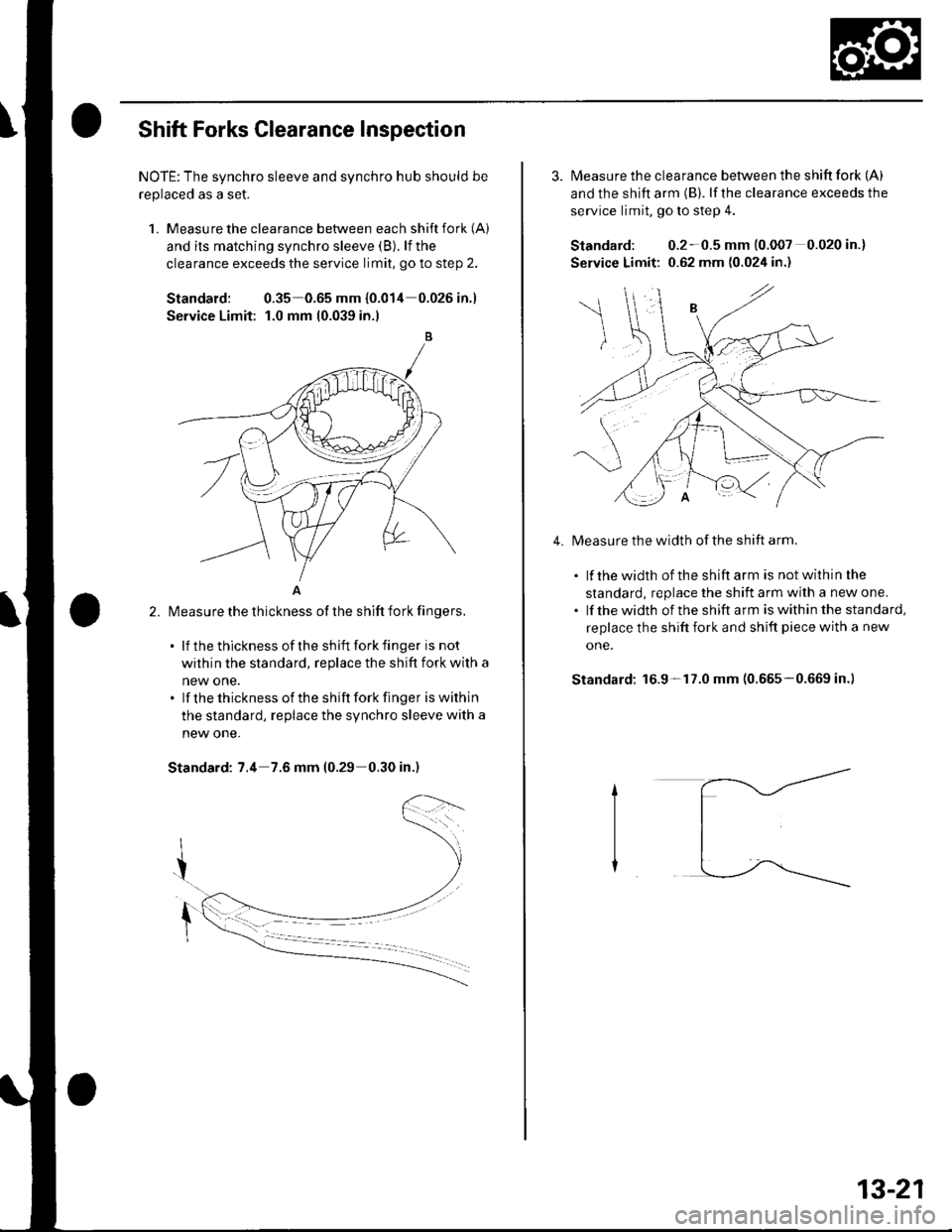
Shift Forks Glearance Inspection
NOTE: The synchro sleeve and synchro hub should be
replaced as a set.
1. Measu re the clearance between each shift fork (A)
and its matching synchro sleeve (B). lf the
clearance exceeds the service limit, go to step 2.
Standard: 0.35 0.65 mm {0.014 0.026in.1
Service Limit: 1.0 mm 10.039 in.l
A
l\4easure the thickness of the shift fork fingers.
. lf thethicknessof theshift forkfinger is not
within the standard, replace the shift fork with a
new one.. lf thethicknessof the shift forkfinger iswithin
the standard, replace the synchro sleeve with a
new one.
Standard: 7.4 7.6 mm (0.29-0.30 in.)
2.
3. Measure the clearance between the shift fork (A)
and the shift arm (B). lf the clearance exceeds the
service limit, go to slep 4.
Standard: 0.2-0.5 mm (0.007 0.020 in.)
Service Limit: 0.62 mm (0.024 in.)
Measure the width of the shift arm.
. lf thewidth of theshiftarm is notwithinthe
standard, replace the shift arm with a new one.. lf thewidth of the shift arm iswithinthe standard,
replace the shift fork and shift piece with a new
one.
Standard: 16.9-17.0 mm (0.665-0.669 in.)
4.
13-21
Page 432 of 1139
Manual Transmission
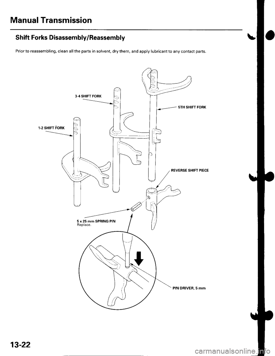
Shift Forks Disassembly/Reassembly
Prior to reassembling, clean all the parts in solvent, dry them, and apply lubricant to any contact parts.
sTH SHIFT FORK
13-22
PIN DRIVER, 5 mm
Page 433 of 1139
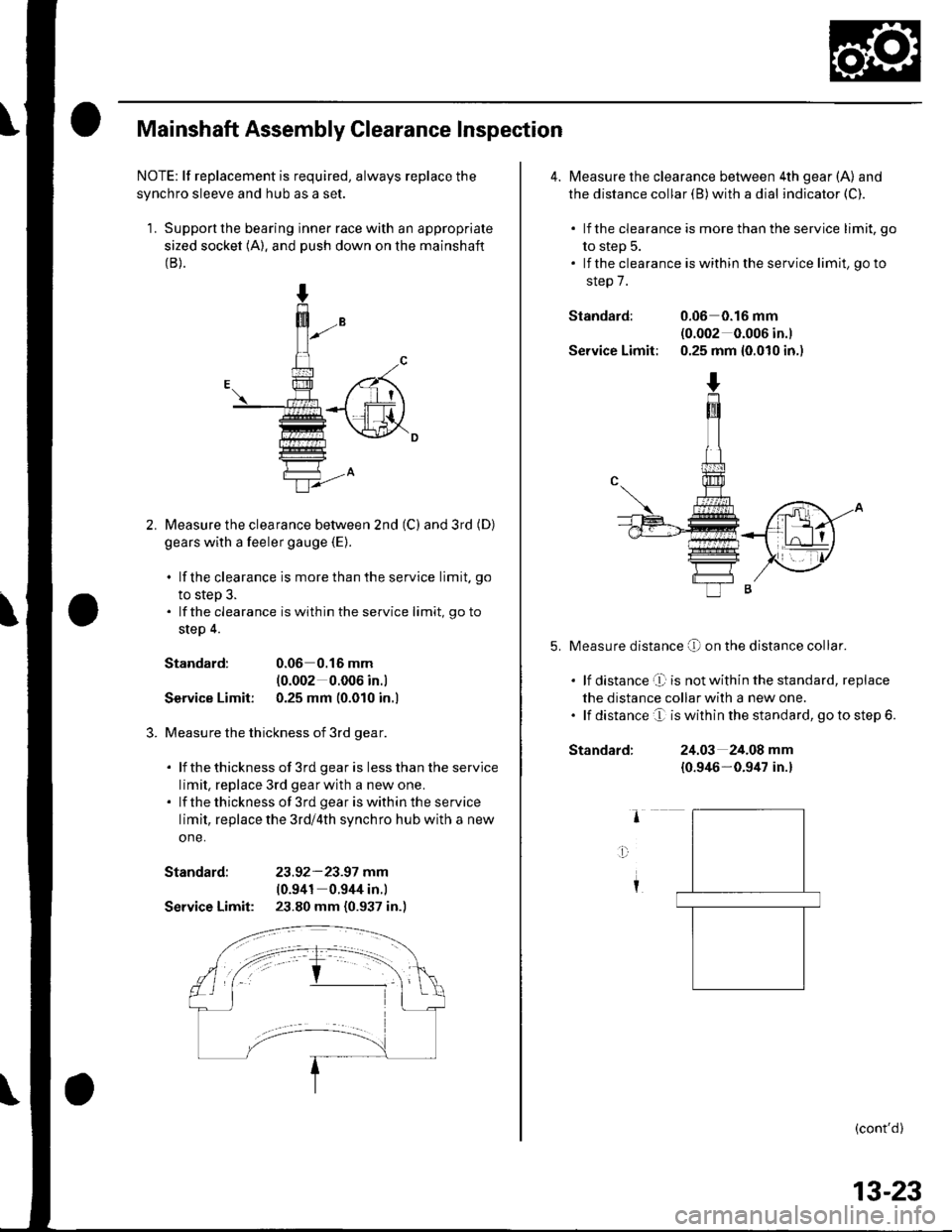
Mainshaft Assembly Clearance Inspection
NOTE: lf replacement is required, always replace the
synchro sleeve and hub as a set.
1. Support the bearing inner race with an appropriate
sized socket (A). and push down on the mainshaft(B).
Measure the clearance bet\iveen 2nd (C) and 3rd (D)
gears with a feeler gauge {E).
. lf the clearance is more than the service limit. go
to step 3.. lf the clearance is within the service limit, go to
step 4.
Standard:0.06 0.16 mm
{0.002 0.006 in.l
Service Limit: 0.25 mm (0.010 in.l
Measure the thickness of 3rd gear.
. lf thethickness of 3rd gearis lessthanthe service
limit, replace 3rd gearwith a new one.. lf thethickness of 3rd geariswithintheservice
limit, replace the 3rd/4th synchro hub with a new
one.
Standard: 23.92-23.97 mm(0.941 0.944 in.)
Service Limit: 23.80 mm (0.937 in.)
4. Measure the clearance between 4th gear (A) and
the distance collar (B) with a dial indicator (C).
. lf the clearance is more than the service limit, go
to step 5.. lf the clearance is within the service limit, go to
step 7.
Standard: 0.06 0.16 mnl(0.002 0.006 in.)
Service Limit: 0.25 mm {0.010 in.)
Measure distance O on the distance co[ar.
. lf distance't is notwithin the standard, replace
the distance collar with a new one.. lf distance e is within the standard, go to step 6.
Standard:24.03 24.08 mm
{0.946-0.9/u in.}
(cont'd)
13-23
Page 434 of 1139
Manual Transmission
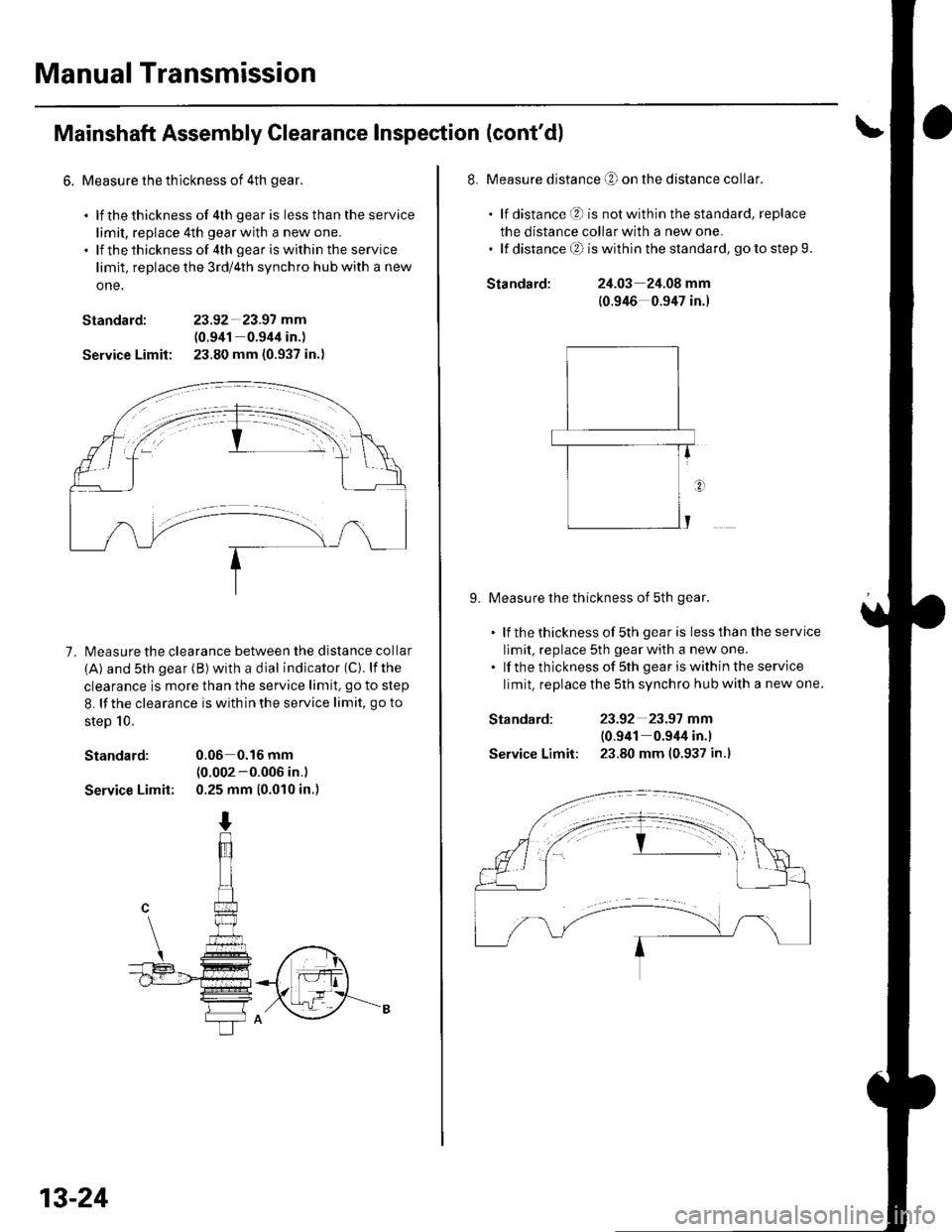
Mainshaft Assembly Clearance Inspection (cont'd)
6. Measure the thlckness of 4th gear.
. lf thethickness of 4th gear is lessthantheservice
limit, replace 4th gear with a new one.. lf thethicknessof 4th geariswithin the service
limit. replace the 3rd/4th synchro hub with a new
one.
Standard: 23.92 23.97 mm
(0.941 0.944 in.)
Service Limit: 23.80 mm (0.937 in.)
7. l\4easure the clearance between the distance collar
(A) and sth gear (B) with a dial indicator (C). lfthe
clearance is more than the service limit. go to step
8. lf the clearance is with in the service limit, go to
steD 10.
Standard: 0.06 0.16 mm(0.002-0.006 in.)
Service Limit: 0.25 mm (0.010 in.)
13-24
Standard:
Standard:
Service Limit:
8. Measure distance O on the distance collar.
. lf distance O is notwithinthestandard, replace
the distance collar with a new one.' lf distanceO iswithinthe standard, gotostep9.
24.03 24.08 mm
(0.946 0.947 in.)
9. Measure the thickness of 5th gear.
. lf thethicknessof 5th gearis lessthantheservice
limit, replace 5th gear with a new one.. lf the thickness of sth gear iswithin the service
limit. replace the 5th synchro hub with a new one.
23-92 23.97 mm
10.941 0.944 in.l
23.80 mm (0.937 in.l
Page 435 of 1139
'10. Measure the thickness ofthe MBS distance collar.
. lf the thickness of MBS distance collar is less
than the standard, replace the MBS distance
collar with a new one.
Standard:23.95 24.05 mm
{0.9(3 0.947 in.)
E-f
Mainshaft Disassembly
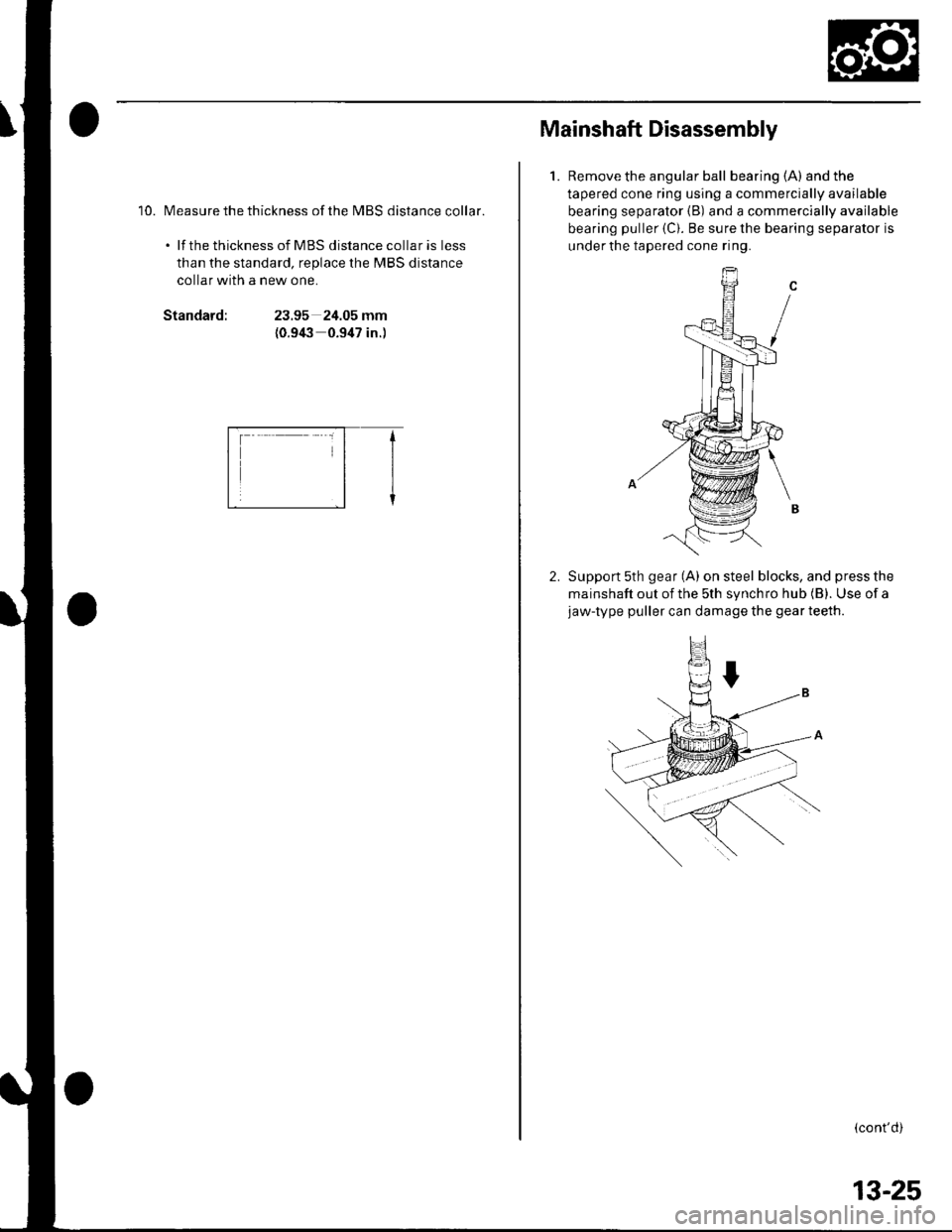
1.Remove the angular ball bearing (A) and the
tapered cone ring using a commercially available
bearing separator {B) and a commercially available
bearing puller {C). Be sure the bearing separator is
under the tapered cone ring.
Support 5th gear (A) on steel blocks, and press the
mainshaft out of the sth synchro hub (B). Use of ajaw-type puller can damage the gear teeth.
(cont'd)
13-25
Page 436 of 1139
Manual Transmission
Mainshaft Disassembly (cont'dl
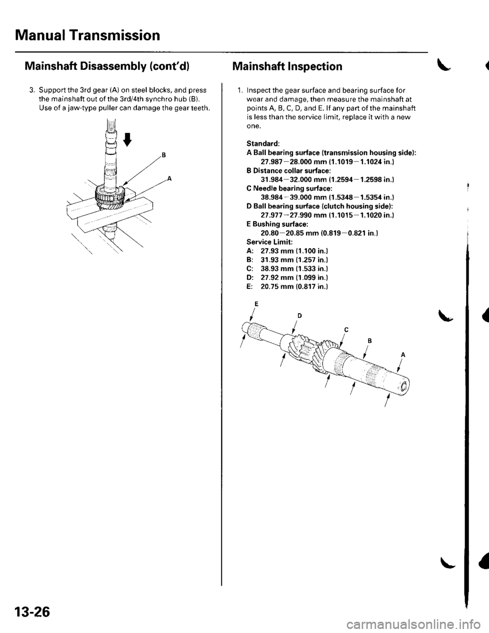
3. Supportthe 3rd gear (A) on steel blocks, and press
the mainshaft out of the 3rd/4th synchro hub (B).
Use of a jaw-type puller can damage the gear teeth.
13-26
Mainshaft Inspection
1. Inspect the gear surface and bearing surface for
wear and damage, then measure the mainshaft at
points A, B, C, D, and E. lf any part of the mainshaft
is less than the service limit, reDlace it with a new
o ne.
Standard:
A Ball bearing surface (transmission housing side):
27.987 28.000 mm (1.1019 1.1024in.)
B Distance collar surtace:
31.984 32.000 mm {1.2594 1.2598in.)
C Needle bearing surlace:
38.984-39.000 mm (1.53/t8 1.5354 in.)
D Ball bearing surface (clutch housing side):
27 .977 -27 .990 mm (1.1015 1.1020in.)
E Bushing surface:
20.80 20.85 mm (0.819 0.821 in.)
Service Limit;
A: 27.93 mm 11.100 in.l
B: 31.93 mm |.1.257 in.l
C: 38.93 mm 11.533 in.l
Di 27.92 mm {1.099 in.l
E: 20.75 mm 10.817 in.l
{
Page 437 of 1139
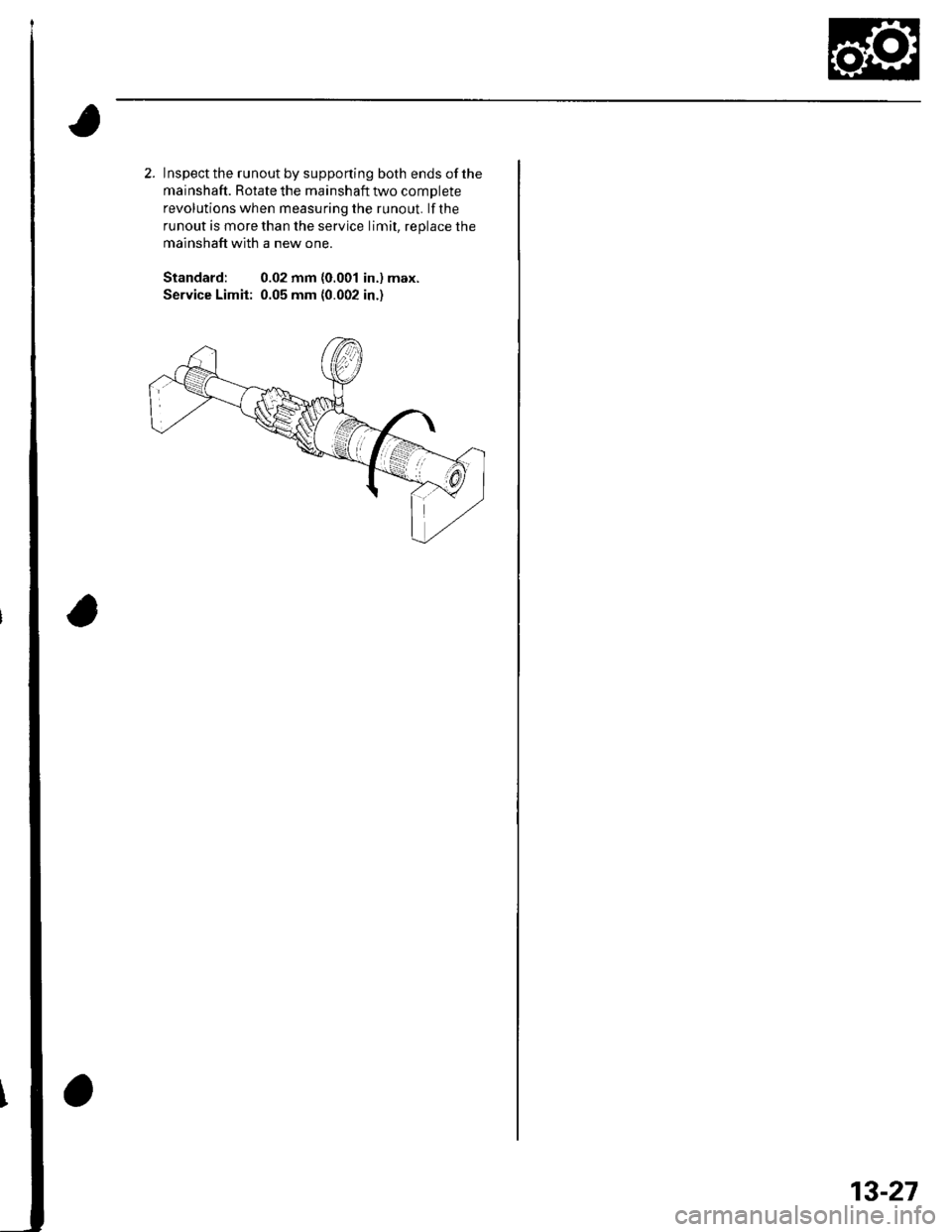
2. Inspect the runout by supponing both ends of the
mainshaft. Rotate the mainshaft two complete
revolutions when measuring the runout. lf the
runout is more than the service limit. reolace the
mainshaft with a new one.
Standard: 0.02 mm (0.001 in.) max.
Service Limit: 0.05 mm (0.002 in.)
13-27
Page 438 of 1139
Manual Transmission
Mainshaft Reassembly
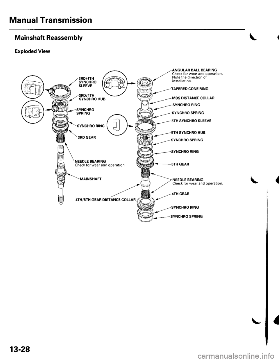
Exploded View
A
QJ'
frfl
Y7
ANGULAB BALL BEARINGCheck for wear and operation.Note the direction ofinstallation.3RD/4THSYNCHROSLEEVE
3RD/4THSYNCHRO HUB
SYNCHROSPRING
SYNCHRO RING
TAPEBED CONE RING
MBS DISTANCE COLLAR
SYNCHRO SLEEVE
NEEDLE BEARINGCheck for wear and operation.
GEAR
SYNCHRO RING
SYNCHRO SPRING
NEEDLE BEARINGCheck for wear and operation.
MAINSHAFT
4TH/5TH GEAB DISTANCE COLLAR
\(
a
13-28
Page 439 of 1139
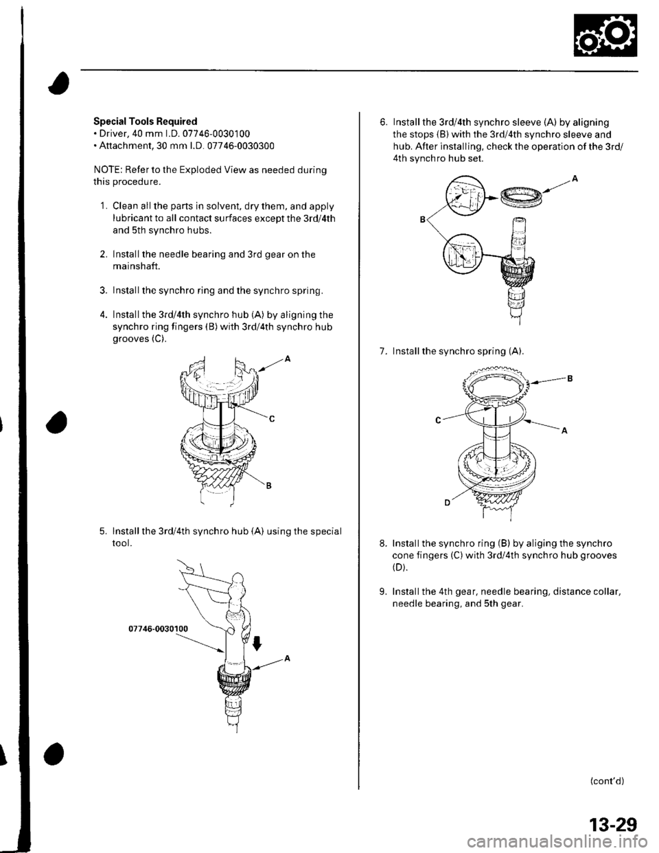
Special Tools Required. Driver,40 mm 1.D.07746-0030100. Attachment,30 mm l.D. 07746-0030300
NOTE: Refer to the Exploded View as needed during
this procedu re.
2.
4.
'1.Clean all the parts in solvent, dry them, and apply
lubricant to all contact su rfaces except the 3rd/4th
and 5th synchro hubs.
Installthe needle bearing and 3rd gear on the
mainshaft.
Installthe synchro ring and the synchro spring.
Installthe 3rd/4th synchro hub (A) by aligning the
synchro ring fingers (B)with 3rd/4th synchro hub
grooves (C).
-A
lnstallthe 3rd/4th synchro hub {A) using the special
tool.
07746-0030100
6. Installthe 3rd/4th synchro sleeve (A) by aligning
the stops (B)with the 3rd/4th synchro sleeve and
hub. After installing, check the operation of the 3rd/
4th synchro hub set.
@--
7. Installthe synchro spring (A).
Installthe synchro ring (B) by aliging the synchro
cone fingers (C)with 3rd/4th synchro hub grooves
(D).
Installthe 4th gear, needle bearing, distance collar,
needle bearing, and sth gear.
(cont'd)
9.
13-29
Page 440 of 1139
Manual Transmission
Mainshaft Reassembly (cont'dl
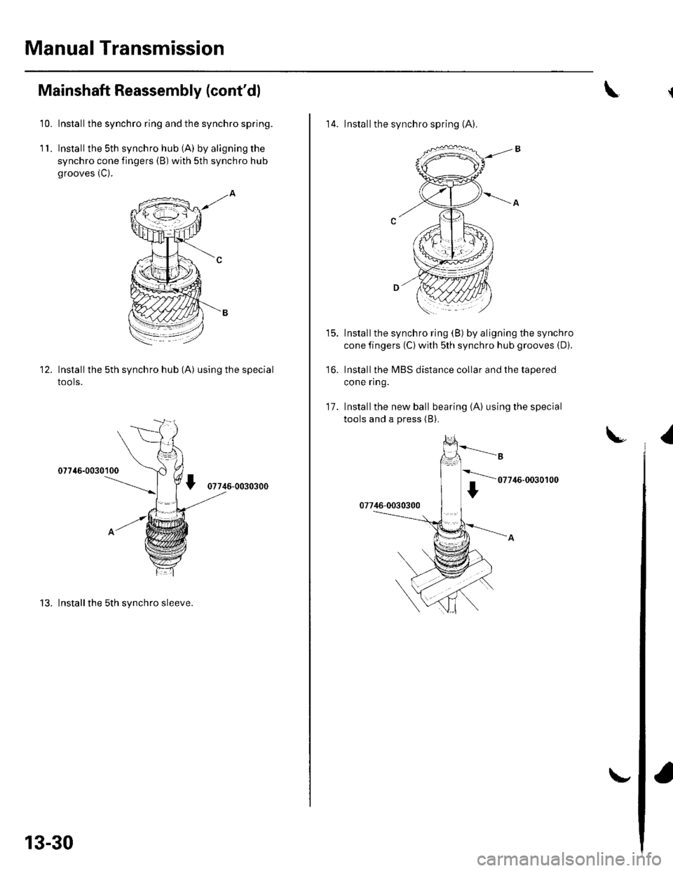
10. Installthe synchro ring and the synchro spring.
1 '1. Installthe sth synchro hub (A) by aligning the
synchro cone fingers (B) with sth synchro hub
grooves (C).
Installthe 5th synchro hub (A) using the special
tools.
07746-0030100
07746-0030300
13. Installthe 5th synchro sleeve.
12.
13-30
\.
\
14. Installthe synchro spring (A).
Installthe synchro ring (B) by aligning the synchro
cone fingers (C) with sth synchro hub grooves (D).
Installthe MBS distance collar and the tapered
cone ring.
Installthe new ball bearing {A) using the special
tools and a press (B).
t5.
16.
11.
U1
07746-0030100