HONDA CIVIC 2003 7.G Workshop Manual
CIVIC 2003 7.G
HONDA
HONDA
https://www.carmanualsonline.info/img/13/5744/w960_5744-0.png
HONDA CIVIC 2003 7.G Workshop Manual
Trending: Steering, oil type, wheel size, multiplex control unit under dash, diagnostic menu, indicator relay, Diesel
Page 421 of 1139
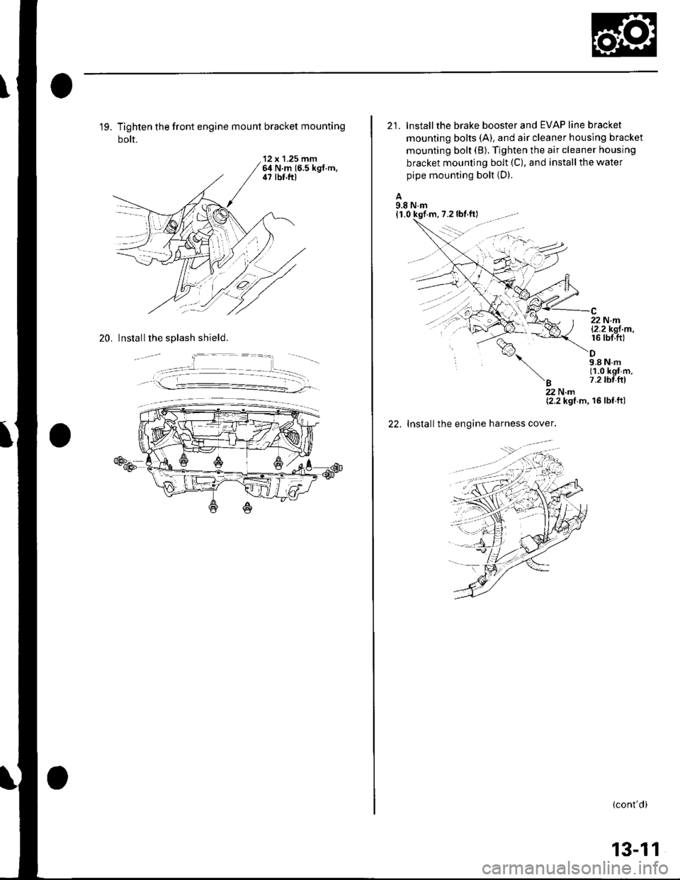
19. Tighten the front engine mount bracket mounting
bolt.
'12 x 1.25 mm64 N.m 16.5 kgf.m,il7 lbf.ft)
20. Install the splash shield.
21. lnstallthe brake booster and EVAP line bracket
mounting bolts (A). and air cleaner housing bracket
mounting bolt (B). Tighten the air cleaner housing
bracket mounting bolt (C), and install the water
pipe mounting bolt (D).
A9.8 N.m(1,0 kqf
%,
'B
22 N.ml2.2kgl m,16 rbt.ft)
9.8Nm(1.0 kgf m.7.2 tbl{rl
22.
22Nm{2.2 kgf m, 16 lbf ft)
Installthe engine harness cover.
(cont'd)
13-11
Page 422 of 1139
Manual Transmission
Transmission Installation (cont'dl
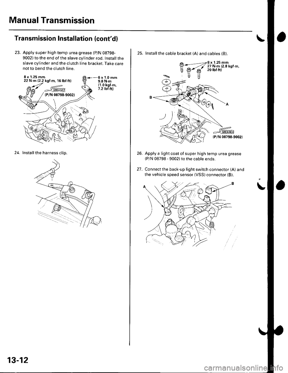
Apply super high temp urea grease (P/N 08798-
9002) to the end of the slave cylinder rod. Install the
slave cylinder and the clutch line bracket. Take care
not to bend the clutch line.
8 x 1.25 mm22 N.m (2.2 kgf.m, 16 lbf ft)6x1.0mm9.8 N.m(1.0 kgf.m,7.2 tbt.ftla^_#._gEEa9En(P/N 08798-9002)
24. Installthe harness clip.
13-12
25. Installthe cable bracket (A) and cables (B).
BWZ[i:i'u'T!'*n'-'
lPlN 08798-9002)
Apply a light coat of super high temp urea grease(P/N 08798 - 9002)to the cable ends.
Connect the back-up light switch connector (A) and
the vehicle speed sensor {VSS)connector (B).
26.
t1
Page 423 of 1139
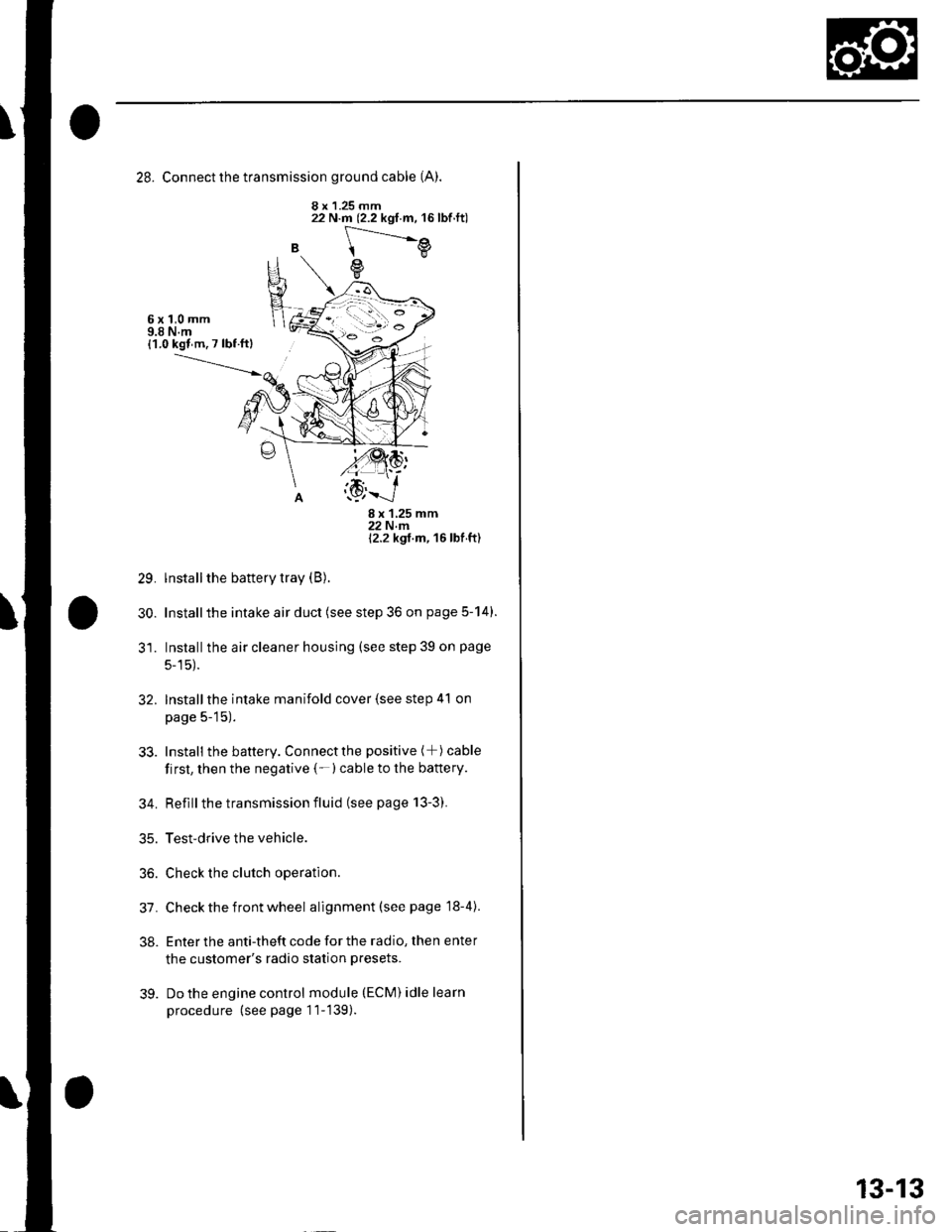
28. Connect the transmission ground cable (A).
8 x 1.25 mm
B
22 N.m (2.2 kgf.m, 16lbf.ft)
[---.-.---e
e
6x1,0mm9.8 N.m{1.0 kgl m. 7 lbf ftl
29.
30.
8x125mm22Nm12.2 kgt m, 16 lbf ft)
lnstall the battery tray (B).
Installthe intake air duct (see step 36 on page 5-14).
Installthe air cleaner housing (see step 39 on page
5-15).
Installthe intake manifold cover (see step 41 on
page 5-15).
Install the battery. Connectthe positive (+) cable
first, then the negative (-)cable to the battery.
Reflllthe transmission fluid (see page 13-3).
Test-drive the vehicle.
Check the clutch operation.
Check the front wheel alignment (see page 18-4).
Enter the anti-theft code for the radio, then enter
the customer's radio station presets.
Do the engine control module (ECM) idle learn
procedure (see page 11-139).
32.
33.
34.
35.
36.
31.
38.
39.
13-13
Page 424 of 1139
Manual Transmission
Transmission Disassembly
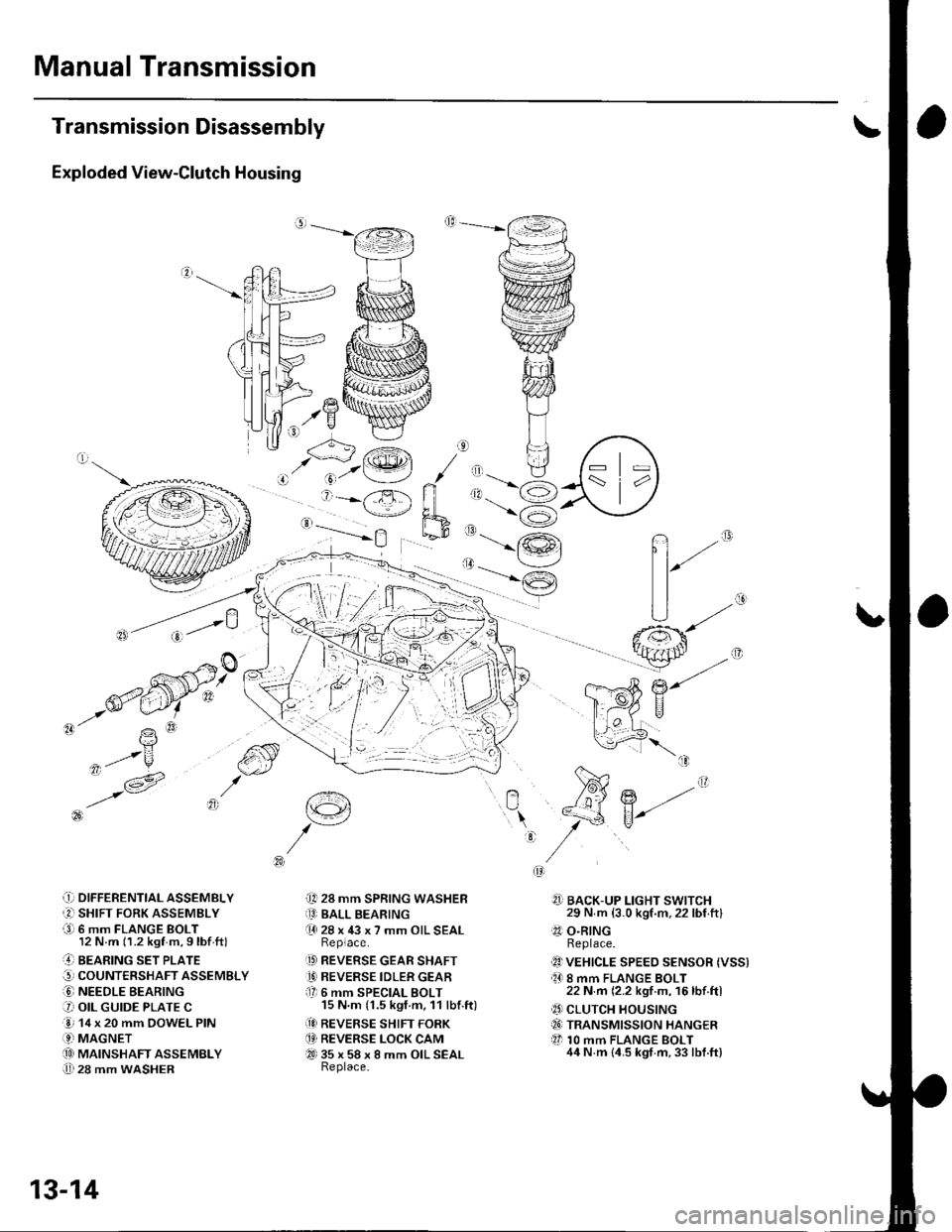
Exploded View-Clutch Housing
,.Y
-'- R
,ot/u
,t- v -1A' i6 t3l
\?
q'/V^
.!) DIFFERENTTAL ASSEMBLY
r2l SHIFT FORK ASSEMBLY
a9l 6 mm FLANGE BOLT12 N.m (1.2 kgf m,9lbf ftl
..4] BEARING sET PLATE
G, COUNTERSHAFT ASSEMBLY
O NEEDLE BEARING
3 OIL GUIDE PLATE C
e 14 x 20 mm DOWEL PIN
.9-i MAGNETi.!! MAINSHAFT ASSEMBLY
U 28 mm WASHER
t€4
i[, 28 mm SPRING WASHERiO BALL BEARING(l 28 x 43 x 7 mm OIL SEALReplace.
.D REVERSE GEAR SHAFT
1' REVERSE IDLER GEARf lr 6 mm SPECIAL BOLT15 N.m (1.5 kgt.m, 11 lbf.ft)
(!I REVERSE SHIFT FORK
.4' REVERSE LOCK CAMQ-t 35 x 58 x 8 mm OIL SEALReplace.
n""
?]] BACK-UP LIGHT SWITCH29 N m (3.0 kgf.m,22 lbf ftl.?1 O.RINGReplace.
1!) VEHICLE SPEEo sENsoR (Vss).O 8 mm FLANGE BOLT22 N.m (2.2 kgf m, 16lbf.ftl
.' CLUTCH HOUSINGiI6) TRANSMISSION HANGER
tl 10 mm FLANGE BOLT44 N.m {4.5 kgt.m,33 lbf.ft}
:
r'<__J'.@t / ,, tl
' j=-X ri ,1.-6
'-==-Yh,_-9
13-14
Page 425 of 1139
o,. @\
'\b
e
P\B
z-W
-
€:
iq { "
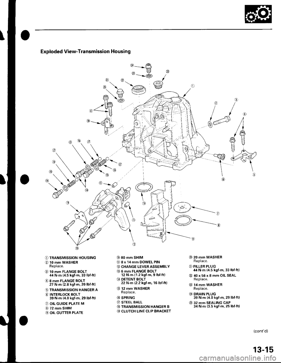
Exploded View-Transmission Housing
@------
tt-P
"=-@
{i) 80 mm SHIM
0 8 x 14 mm DOWEL PIN
[A CHANGE LEVER ASSEMBLY
a0 6 mm FLANGE BOLT12 N m {1.2 kgf.m,9 lbf ft}
O DETENT BOLT22 N.m {2.2 kgf.m, 16lbf.ft)
O 12 mm waSHERReDlace.
(D SPRING
[I STEEL BALL(D TRANSMISSION HANGER B(9 CLUTCH LINE CLIP BRACKET
@
rai\€:/
o
f/
dd
\@
O=-rlF,z
O TRANSMISSION HOUSING
O 10 mm WASHERReplace.
@ 10 mm FLANGE BOLT44 N.m {4.5 kgf.m,33lbf.ft)
O 8 mm FLANGE BOLT27 N.m 12.8 kgf m,20lbl.ft)
.' TRANSMISSION HANGER A
O INTERLOCK BOLT39N m (4.0ksf.m,29lbf.ft)
O OIL GUIOE PLATE M
€.1 72 mm SHIM
.' OIL GUTTEB PLATE
,-1 _\(g/----------__-
"^\
\-/r*---------..-,
@) 20 mm WASHERReplace.
q,] FILLER PLUG44 N m {4.5 kgf.m,33 lbf.ft)
@ 40 x 56 x 8 mm OILSEALReplace.
qO 14 mm WASHERReplace.
q' DRAIN PLUG39 N.m (4.0 kgf.m,29 lbf.ftl
@ 32 mm SEALING CAP34 N m (3.5 kgf.m, 25 lbf.ft)
o
(cont'd)
13-15
Page 426 of 1139
Manual Transmission
Transmission Disassembly (cont'd)
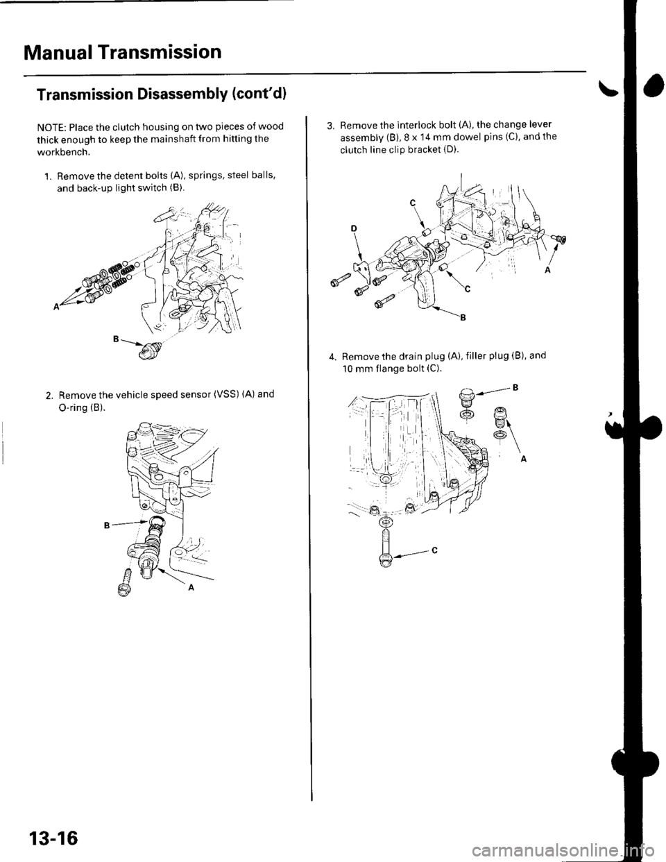
NOTE: Place the clutch housing on two pieces of wood
thick enough to keep the mainshaft from hitting the
workbench.
1. Remove the detent bolts (A), springs, steel balls,
and back-up light switch (B).
Remove the vehicle speed sensor (VSS) (A) and
O-ring (B).
13-16
3, Remove the interlock bolt (A), the change lever
assembly (B), 8 x 14 mm dowel pins (C), andthe
clutch line clip bracket {D).
€
Remove the drain plug (A), filler plug (B), and
10 mm flange bolt (C).
Page 427 of 1139
6.
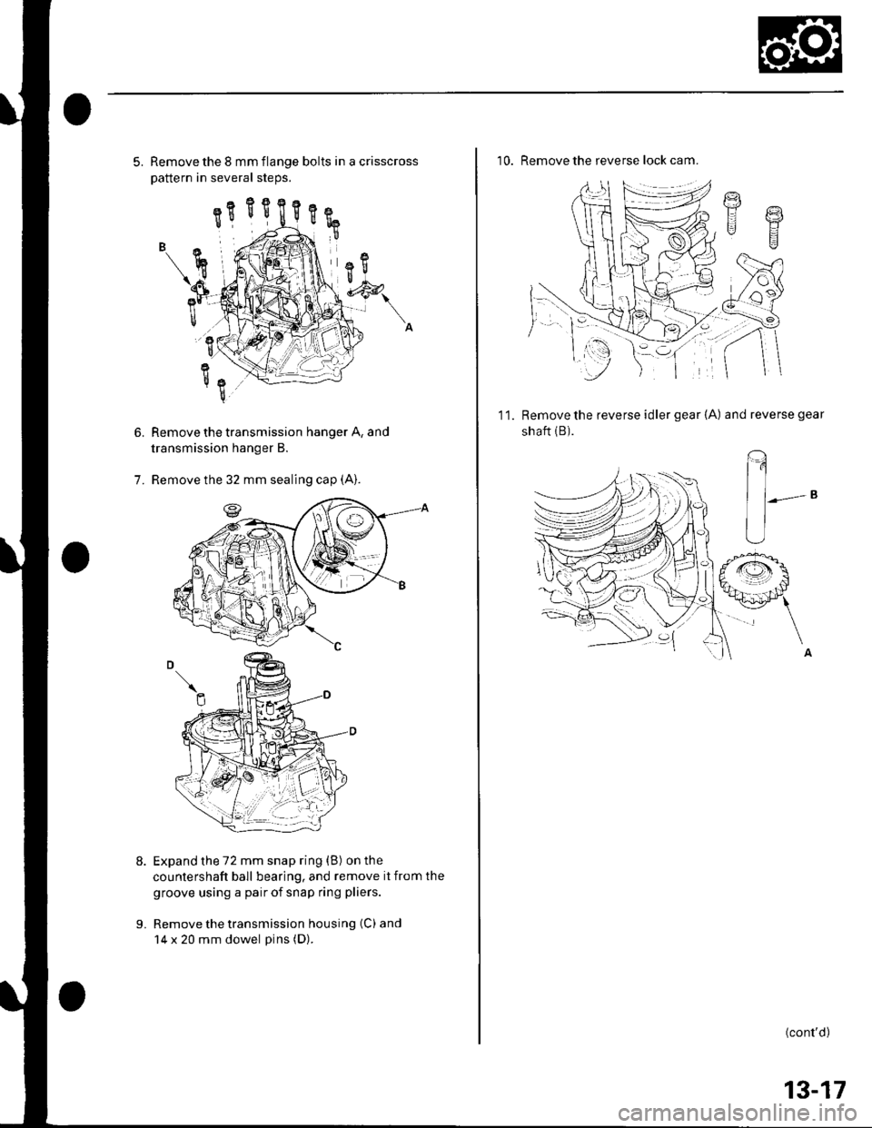
5. Remove the 8 mm flange bolts in a crisscross
Dattern in several steos.
Remove the transmission hanger A, and
transmission hanger B.
Remove the 32 mm sealing cap (A).
Expand the 72 mm snap ring (B) on the
countershaft ball bearing, and remove it from the
groove using a pair of snap ring pliers.
Remove the transmission housing (C) and
14 x 20 mm dowel pins (D).
7.
L
10. Remove the reverse lock cam.
g
t.l Y
g
11.Remove the reverse idler gear {A) and reverse gear
shaft {B).
(,
^A
(cont'd)
13-17
Page 428 of 1139
Manual Transmission
Transmission Disassembly (cont'd)
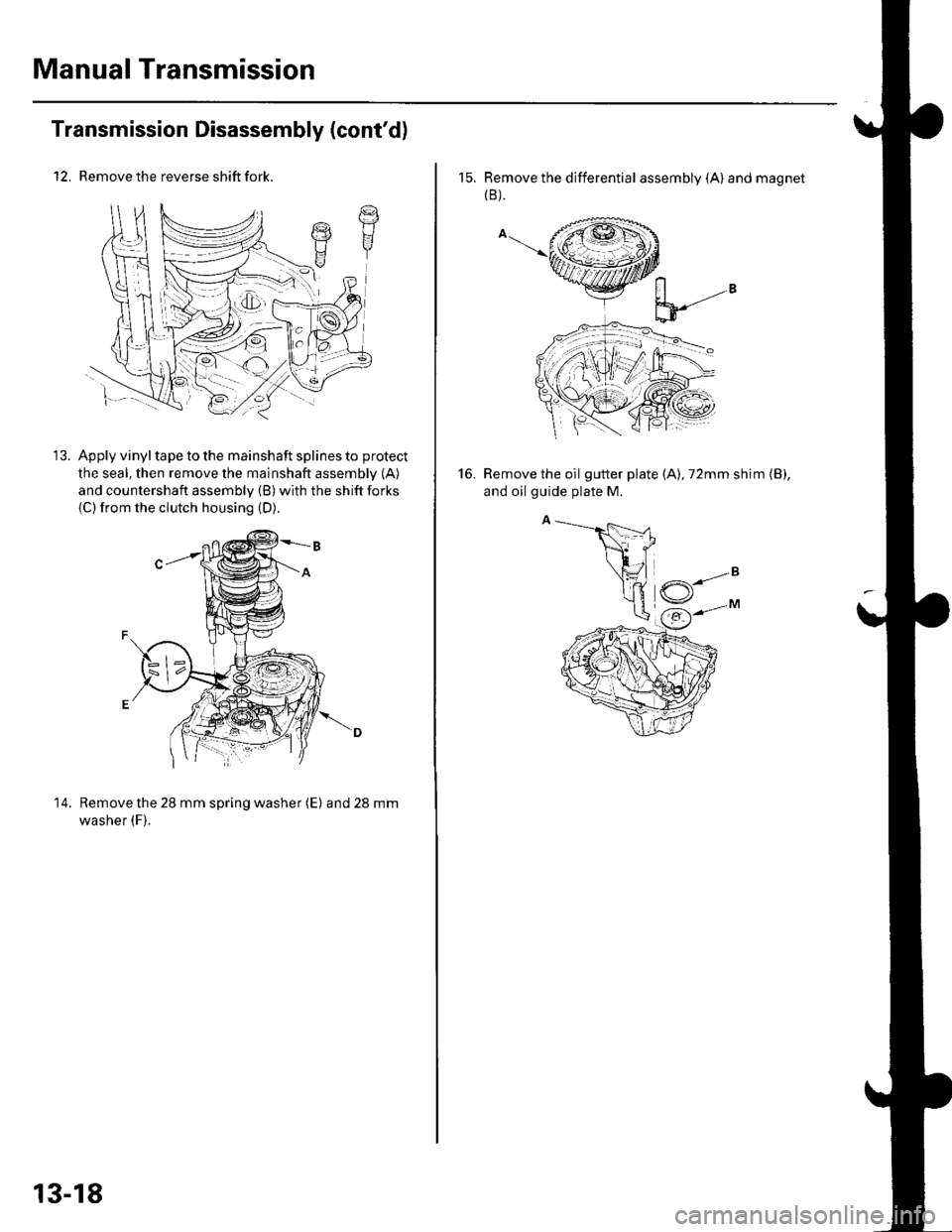
12. Remove the reverse shift fork.
Apply vinyl tape to the mainshaft splines to protect
the seal, then remove the mainshaft assembly (A)
and countershaft assembly (B) with the shift forks
{C)from the clutch housing (D).
14. Remove the 28 mm spring washer (E) and28mm
washer (F).
t7t1I
13-18
15. Remove the differential assembly (A) and magnet(B ).
Remove the oil gutter plate (A), 72mm shim (B),
and oil guide plate M.
16.
Page 429 of 1139
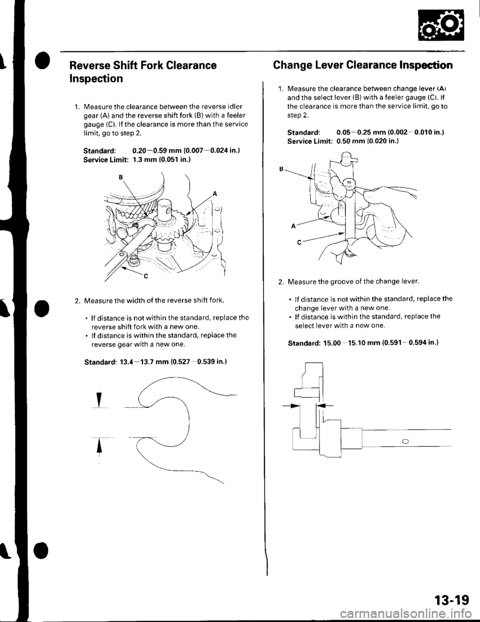
Reverse Shift Fork Clearance
Inspection
1. Measure the clearance between the reverse idler
gear {A) and the reverse shift fork (B) with a feeler
gauge (C). lf the clearance is more than the service
limit, go to step 2.
Standard: 0.20-0.59 mm (o.oo7 0.024 in.l
Service Limit: r.3 mm {0.051 in.)
Measu re the width of the reverse shift fork.
. lf distance is notwithinthestandard, replacethe
reverse shift fork with a new one.. lf distance is within the standard, replacethe
reverse gear wrln a new one.
Standard: 13.4 13.7 mm (0.527 0.539 in.l
I
Change Lever Clearance Inspection
1.Measure the clearance between change lever (Al
and the select lever (B) with a feeler gauge (Cf. lf
the clearance is more than the service limit, go ro
step 2.
Standard: 0.05 0.25 mm (0.002-0.010 in.)
Service Limit: 0.50 mm {0.020 in.)
2.Measure the groove of the change lever'
. lf distance is not within the standard, replace the
change lever with a new one.
. lf distance iswithinthe standard, replacethe
select lever with a new one.
15.00 15.10 mm (0.591-0.594 in.)Standard:
,tl
I
qI
13-19
Page 430 of 1139
Manual Transmission
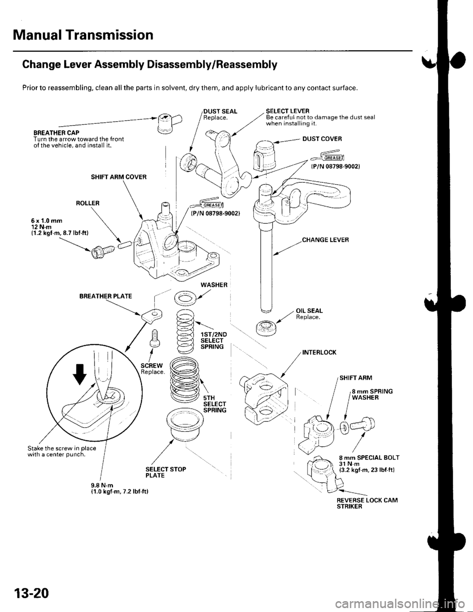
Change Lever Assembly Disassembly/Reassembly
Prior to reassembling, clean all the parts in solvent, dry them, and apply lubricant to any contact surface.
BREATHER CAPTurn the arrow toward the {ronto{ the vehicle, and install it.
SELECT LEVERBe careful not to damage the dust sealwhen installing it.@).1 IlLrl
rrl
I
DUST COVEB
a^^
7 Fr"irr6-rooa
(P/N 08798-9002)
ROLLER
6x1.0mm12 N.m(1.2 kgl.m,8.7 lbf.ft)
'^ E-='-Fl !-d 1sr/2Noq )-=^l sELEcr
i €2 sPntruc
,.* (A)tace. ix�#,,l
H\
lV srxSELECT-z:-=:l-': SPRING
r\
tr7
,/u
/
\op
(g)'
' -, OIL SEAL,/ ReDlace./-r,s
\__/
INTERLOCK
SHIFT ARM
SELECT STOPPLATE
REVERSE LOCK CAMSTRIKER
SHIFT ARM COVER
WASHER
9.8Nm{1.0 kgf.m, 7.2 lbf.ft)
13-20
Trending: tire pressure, turn signal, air mix control motor, 20-63, center console, Torque, maintenance reset
