Meter HONDA CR-V 1997 RD1-RD3 / 1.G Manual PDF
[x] Cancel search | Manufacturer: HONDA, Model Year: 1997, Model line: CR-V, Model: HONDA CR-V 1997 RD1-RD3 / 1.GPages: 1395, PDF Size: 35.62 MB
Page 1223 of 1395
o-.
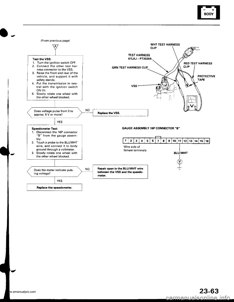
WHT TEST HARNESSCLIP
TEST HARNESSOTLAJ _ PT3O2OA
GRN TEST HARNESS
BED TEST HARNESSct-tP
PROTECTIVETAPE
(From previous page)
T6st the VSS:1. Turn the ignition switch OFF.2, Connect the other test har-ness connector to the VSS,3. Raise the front and rear of thevehicle, and support jt withsafety stands.4. Put the transmission in neu-tral with the ignition switchoN r).5. Slowly rotate one wheel withthe other wheel blocked.
Does voltage pulse from 0 toapprox, 5 V or more?
Spoodom6tor T6st:1, Disconnect the 16P connector"B" from the gauge assem
2. Touch a probe to the BLUMHTwire. and connect it to bodyground through a voltmeter.3. Slowly rotate one wheel withthe other wheel blocked.
R.p.ir opon in the BLU/WHT wirebetwe€n the VSS and the 3oeedo-mgter.
Does the meter indicate puls-ing voltage?
GAUGE ASSEMBLY 16P CONNECTOR 'B-
Wire side offemale termin6lsBLU/WHT
I(v)
It
23-63
www.emanualpro.com
Page 1272 of 1395
Rear Window Defogger
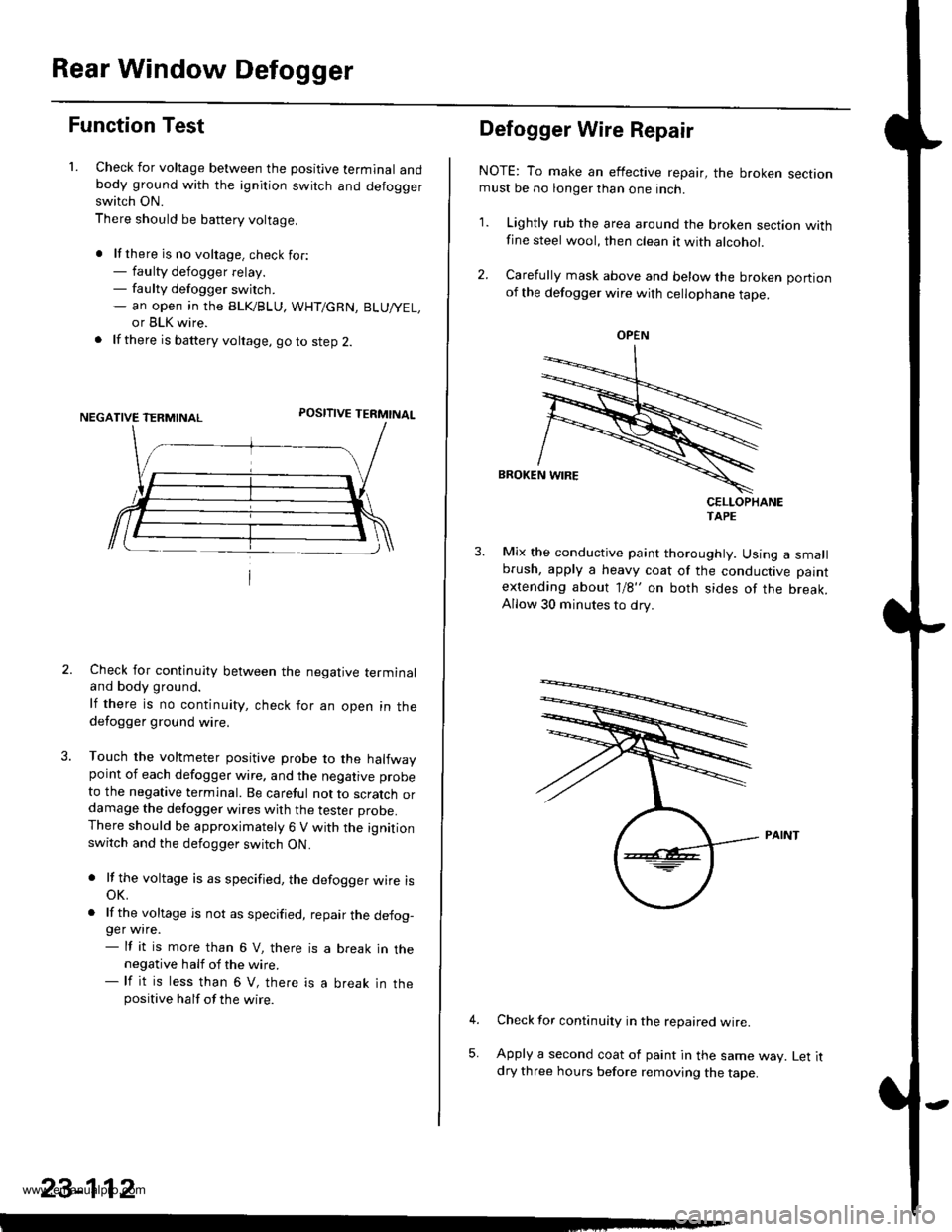
Function Test
1. Check for voltage between the positive terminal andbody ground with the ignition switch and defoggerswitch ON.
There should be battery voltage.
. lf there is no voltage. check for:- faulty defogger relay.- faulty defogger switch.- an open ,n the BLK/BLU, WHT/GRN, BLU/YEL,
or BLK wire.
. lf there is battery voltage, go to step 2.
POSITIVE TERMINAL
Check for continuity between the negative terminaland body ground.
lf there is no continuity, check for an open in thedefogger ground wire.
Touch the voltmeter positive probe to the halfwaypoint of each defogger wire, and the negative probe
to the negative terminal. Be careful not to scratch ordamage the defogger wires with the tester probe.There should be approximately 6 V with the ignitionswitch and the defogger switch ON.
. lf the voltage is as specified, the defogger wire isoK.
. lf the voltage is not as specified, repair the defog-ger wire.- lf it is more than 6 V, there is a break in thenegative half of the wire.- lf it is less than 6 V, there is a break in thepositive half of the wire.
23-112
Defogger Wire Repair
NOTE: To make an effective repair, the broken sectionmust be no longer than one inch.
1. Lightly rub the area around the broken section withfine steel wool, then clean it with alcohol.
2. Carefully mask above and below the broken portionof the defogger wire with cellophane tape.
CELLOPHANETAPE
Mix the conductive paint thoroughly. Using a smallbrush, apply a heavy coat of the conductive paint
extending about 1/8" on both sides of the break.Allow 30 minutes to dry.
Check for continuity in the repaired wire.
Apply a second coat of paint in the same way. Let itdry three hours before removing the tape.
5,
OPEN
www.emanualpro.com
Page 1279 of 1395
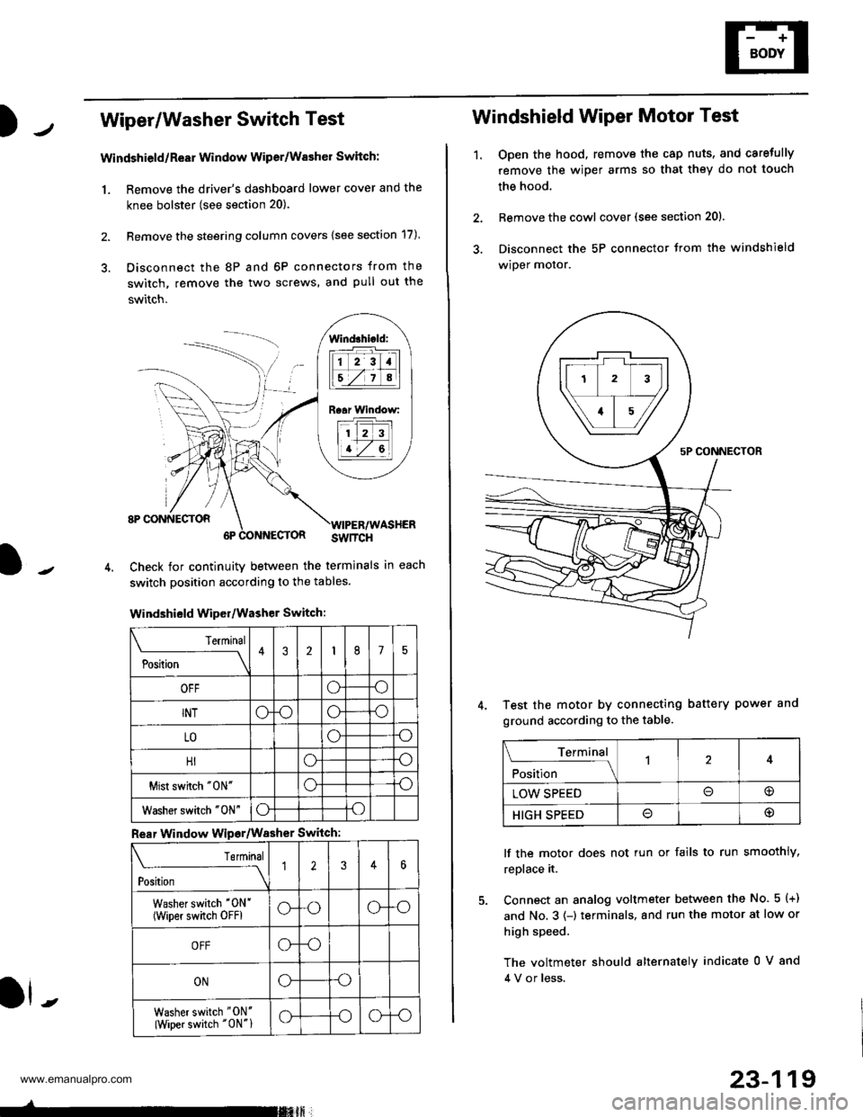
Wiper/Washer Switch Test
Windshield/ReEr Window Wiper/Washer Switch:
1. Remove the driver's dashboard lower cover and the
knee bolster (see section 20).
2. Remove the steering column covers {see section 17)
3. Disconnect the 8P and 6P connectors from the
switch, remove the two screws, and pull out the
switch.
J-
lind3hi.ld:
tilt-rltl
IEZIA
Raar Window:
11 2 3
I t-7 al
ll -
Check for continuity betlveen the termlnals in each
switch position according to the tables.
Windshield Wiper/Washer Switch:
Terminal
P*t-
---__\432175
OFFoo
INToooo
LOoo
HIoo
Mist swhch "0N"oo
Washer switch "0N"oo
Rear Window Wipsr/Washer Switch
Teminal
ti'"
---\12346
Washer switch '0N'
(wiper switch oFFlG-oG-o
OFFG-o
ONGo
Washer switch "ON'
(Wiper switch "0N"1G-oG-o
-rmxft
23-119
1.
Windshield Wiper Motor Test
Open the hood, remove the cap nuts, and caretully
remove the wiper arms so that they do not touch
the hood.
Remove the cowl cover (see section 201.
Disconnect the 5P connector trom the windshield
wiper motor.
Test the motor by connecting battery power and
ground according to the table.
lf the motor does not tun or fails to run smoothly,
replace it.
Connect an analog voltmeter between the No. 5 (+)
and No. 3 (-) terminals, and run the motor at low or
high speed.
The voltmeter should alternately indicate 0 V 8nd
4 V or less.
Terminal
;fi;"
-l4
LOW SPEED@
HIGH SPEED@
www.emanualpro.com
Page 1280 of 1395
Wipers/Washers
1.
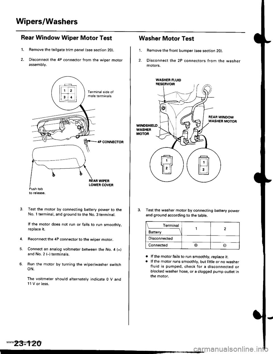
Rear Window Wiper Motor Test
Remove the tailgate trim panel (see section 20),
Disconnect the 4P connector from the wiper motor
assembly.
4P CONNECTOR
WIPEBLOWER COVEnPush tabto release,
Test the motor by connecting battery power to theNo. I terminal, and ground to the No. 3 terminal.
lf the motor does not run or fails to run smoothly,replace it.
Reconnect the 4P connector to the wiper motor.
Connect an analog voltmeter between the No. 4 (+)
and No. 2 (-) terminals.
Run the motor by turning the wiper/washer switchoN.
The voltmeter should alternately indicate 0 V and11 V or less.
4.
5.
23-120
1.
Washer Motor Test
Remove the front bumper (see section 20).
Disconnect the 2P connectors from the washermolors,
REAR WINDOWWASHER MOTOR
Test the washer motor by connecting battery power
and ground according to the table.
lf the motor fails to run smoothly, replace it.lf the motor runs smoothly, but little or no washerfluid is pumped, check for a disconnected orblocked washer hose, or a clogged pump outlet inthe motor.
a
a
L_Iq'.r91
Battery
,l
Disconnected
Connected@
www.emanualpro.com
Page 1287 of 1395
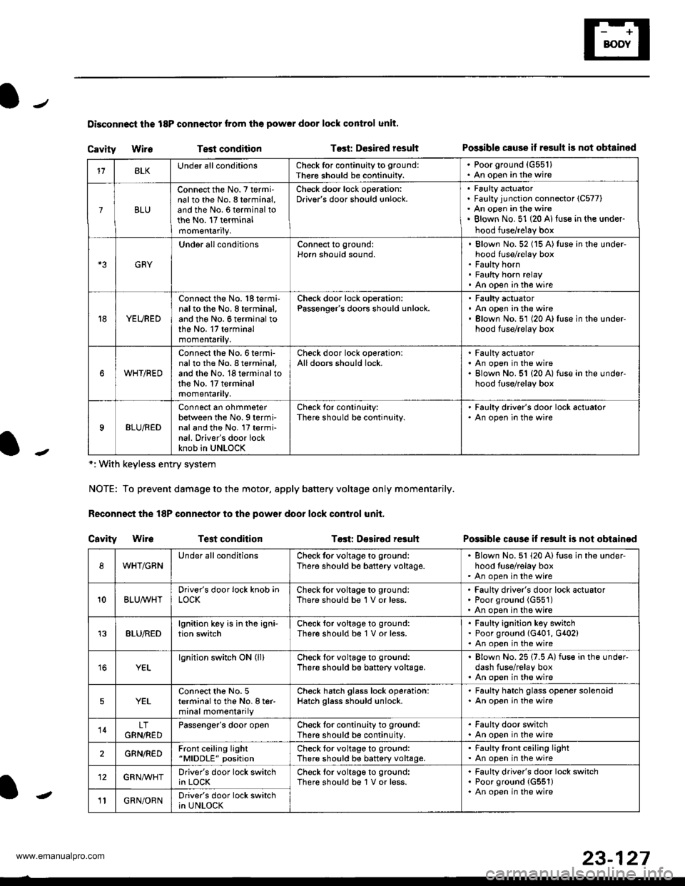
Disconnoci the 18P connestor from the pow€r door lock control unit.
Cavity WireTest conditionTost: Dcsired resultPo$ible csuse il result is not obtainod
Possible cause if result is not obtain€d
*: With keyless entry system
NOTE: To prevent damage to the motor, apply battery voltage only momentarily.
Feconnoct the 18P conneqtor to the power door lock control unit,
Cavity Wir6Test conditionTost: D€sirod result
118LKUnder all conditionsCheck for continuity to ground:
Ther€ should be continuity.
. Poorground (G55'l). An open in the wire
7BLU
Connect the No. 7 termi'nalto the No. 8 terminal,and the No. 6 terminal tothe No. 17 terminalmomentarily.
Check door lock operation:Driver's door should unlock.Faulty actuatorFaulty junction connector (C577)
An open in the wireBlown No. 51 (20 Al{use in the under-
hood fuse/relay box
GRY
Under all conditionsConnect to ground:Horn should sound,Blown No. 52 (15 A)tuso in the under-hood fuse/relay boxFaulty hornFaulty horn relayAn open in tho wire
YEURED
Connect the No. 'l8 termi-nalto the No. 8 terminal,and the No. 6 terminal tothe No. 17 terminalmomentarily.
Check door lock operation:Passenger's doors should unlock.Faulty actuatorAn open in the wireBlown No.51 (20 A)fuse in the under-hood fuse/relay box
WHT/RED
Connect the No.6termi-nal to th6 No. I terminal,and the No. 18 terminal tothe No. 17 terminalmomentarily.
Check door lock operationlAll doors should lock.Faulty actuatorAn open in the wireBlown No. 51 {20 A) fuse in ihe under-hood fuse/relay box
9BLU/RED
Connect an ohmmeterbetween the No. 9 termi-nal and the No. l7 termi-nal. Driver's door lockknob in UNLOCK
Check for conlinuity:There should be continuity.
' Faulty driver's door lock actualor. An open in the wire
WHT/GRNUnder all conditionsCheck for voltage to ground:
There should be battery voltage.Blown No. 51 (20 Alfuse in the under-hood tuse/relay boxAn open in the wire
10BLUAVHTDriver's door lock knob inLOCKCheck tor voltage to ground:There should be 1 V or less.Faulty driver's door lock actuatorPoor ground (G551)
An open in the wire
13BLU/REDlgnition key is in the igni-tion switchCheck tor voltage to ground:
There should b€ 1 V or less.Faulty ignition key switchPoor ground (G401, G402)An open in the wire
YELlgnition switch ON (ll)Check for voltage to ground:
There should be battery voltage.Blown No. 25 (7.5 A) fuse in the under-dash fuse/relay boxAn open in the wire
5YELConnect the No. 5terminal to the No. I ter-minal momentarily
Check hatch glass lock operation:Hatch glass should unlock.
. Faulty hatch glass opener solenoid. An opon in the wire
14LTGRN,NEDPassengor's door openCheck for continuity to ground:There should b€ continuity.
. Fa(llty door switch. An open in the wire
2GRN/R€DFront ceiling light"MlDDLE" positionCheck tor voltage to ground:There should be battery voltage.Faulty lront ceiling lightAn open in the wire
12GRNAr'VHTDriver's door lock switchin LOCKCheck lor voltage to ground:There should be 1V or less.Faulty driver's door lock switchPoor ground {G551)An open in the wire' GRN/ORNDriver's door lock switchin UNLOCK-
23-127
www.emanualpro.com
Page 1297 of 1395
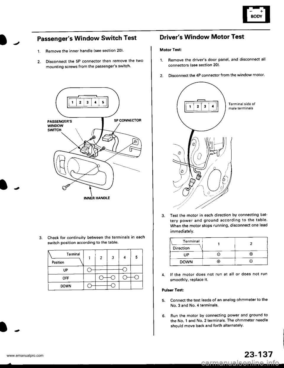
Passenger's Window Switch Test
1.Remove the inner handle (see section 20).
Disconnect the 5P connector then remove the two
mounting screws from the passenger's switch.
Check for continuity between the terminals in each
switch position according to the table
Terminal
;"rL-
__\1235
UPo--o
OFF-oo--o
DOWNo--o
Driver's Window Motor Test
Motor Test:
1. Remove the driver's door panel, and disconnect all
connectors (see section 201.
2. Disconnect the 4P connector from the window motor.
Terminal side ofmale terminals
Test the motor in each direction by connecting bat-
tery power and ground according to the table.
When the motor stops running. disconnect one lead
immediately.
Terminal
;;b"
-\
UPo(!r
DOWN@o
4. lf the motor does not run at all or does not run
smoothly. rePlace it.
Pulser Test:
5. Connect the test leads of an analog ohmmeter to the
No, 3 and No. 4 terminals.
6. Run the motor by connecting power and ground to
the No. 1 and No. 2 terminals. The ohmmeter needle
shquld move back and forth alternately.
23-137
www.emanualpro.com
Page 1316 of 1395
Precautions/Procedures
)General Precautions
Carefully inspect any SRS part before you install it.
Do not install any part that shows signs of being drop-
ped or improperly handled, such as dents, cracks or
deformation:
- Airbags- Cable reel- SRS unit- Seat belt tensioners
N
)-
Use only a digital multimeter to check the system, lf
it's not a Honda multimeter, make sure its output is
10 mA (0,01 A) or less when switched to the smallest
value in the ohmmeter range. A tester with a higher
output could damage the airbag circuit or cause acci-
dental deployment and possible injury.
Do not install used SRS Dans from another vehicle,
When making SRS repairs, use only new pans.
Except when performing electrical inspections,
always disconnect both the negative cable and posi-
tive cable from the batterv. and wait at least three
minutes before beginning work.
Replacement of the combination light and wiper/
washer switches and cruise control switch can be
done without removing the steering wheel:
- Combination light and wiper/washer switch replace-
ment {see section 231.- Cruise control sevresume switch replacement (see
section 41.
Whenever the ignition switch is ON {ll}, or has been
turned OFF for less than three minutes, be careful not
to bump the SRS unit; the airbags could accidentally
deploy and cause damage or injuries.
Whenever the airbag has been activated, replace the
SRS unit.
The original radio has a coded theft protection circuit.
Be sure to get the customer's code number before dis-
connecting the battery cables.
)
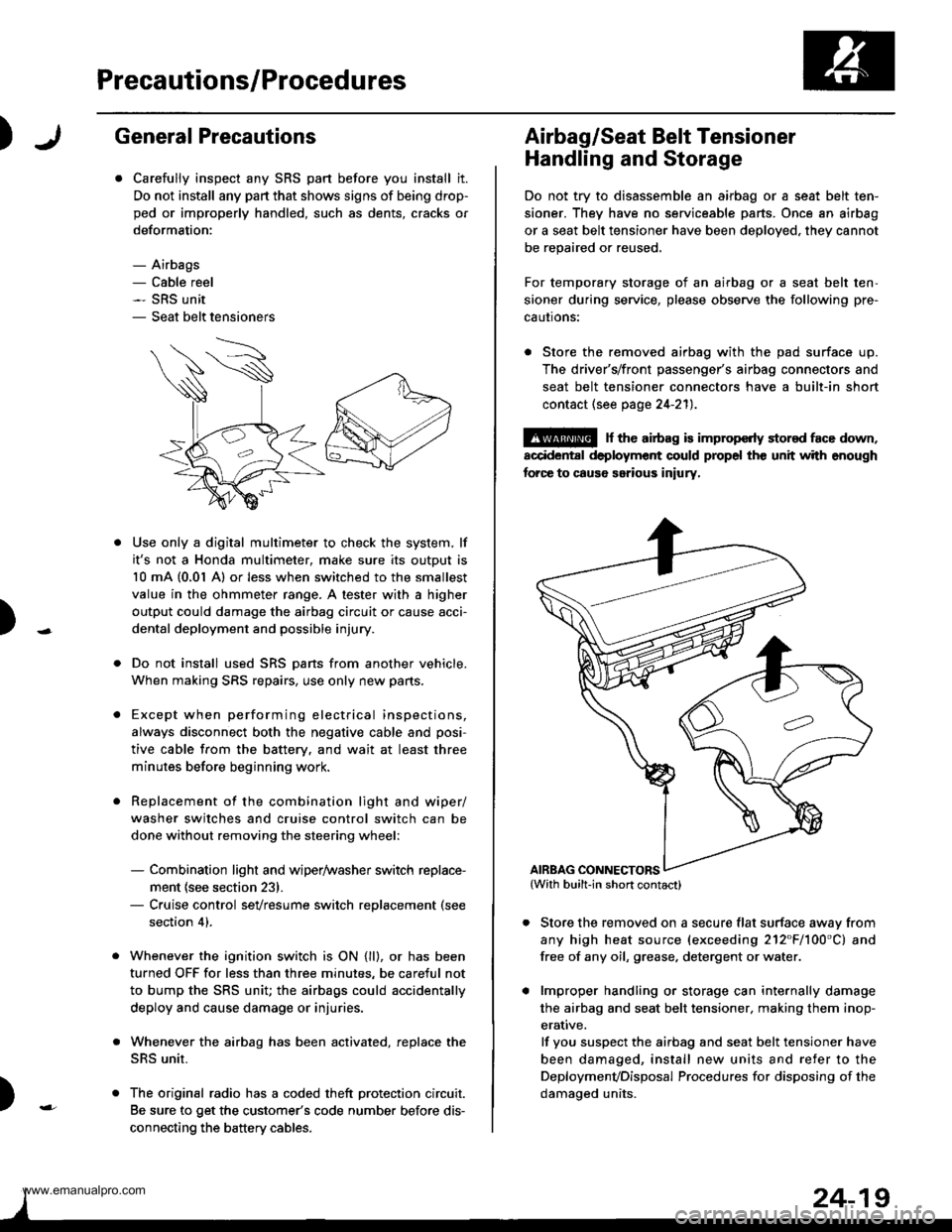
Airbag/Seat Belt Tensioner
Handling and Storage
Do not try to disassemble an airbag or a seat belt ten-
sioner. They have no serviceable parts. Once an airbag
or a seat belt tensioner have been deployed. they cannot
be repaired or reused.
For temporary storage of an airbag or a seat belt ten-
sioner during service, please observe the following pre-
cautons:
. Store the removed airbag with the pad surface up.
The driver's/front passenger's airbag connectors and
seat belt tensioner connectors have a built-in short
contact (see page 24-211.
@ r th€ airb.g is impropcrty stor€d face down,
accidental deployment could propel the unit with enough
forc€ to caus6 serious iniury,
Store the removed on a secure flat surface awav from
any high heat source (exceeding 212"F/100'C) and
free of any oil, grease. detergent or water.
lmproper handling or storage can internally damage
the airbag and seat belt tensioner. making them inop-
erative.
lf you suspect the airbag and seat belt tensioner have
been damaged, install new units and refer to the
Deploymenvoisposal Procedures for disposing of the
damaoed units.
AIRBAG CONNECTORS
www.emanualpro.com
Page 1323 of 1395
Troubleshooting
Self-diagnostic Procedures
The self-diagnostic function of the SRS system allows it to locate the causes of system problems and to store this informa-
tion in memory, For easier troubleshooting, this data can be retrieved via a data link circuit.
. When you turn the ignition switch ON (ll). the SRS indicator will come on. lf it goes off after six seconds, the system is
normal.
. lf there is 8n abnormality, the system locates and defines the problem. stores this information in memory, and turns
the SRS indicator light on. The data will remain in the memory even when the ignition switch is turned off or if the bat-
terv is disconnected.
. When you connect the SCS service connector to the service check connector (2P), and turn the ignition switch ON (ll),
the SRS indicator light will indicate the diagnostic trouble code (DTC) by the number of blinks.
. After reading and recording the DTC, proceed with the troubleshooting forthis code.
Precsutions
. Use only a digital multimeter to check the system. lf it's not a Honda multimeter. make sure its output is 10 mA (0.01 A)
or less when switched to the smallest value in the ohmmeter range. A tester with a higher output could damage the
airbag circuit or cause accidental airbag deployment and possible injury.
. Whenever the ignition switch isON (ll). or has been turned OFF for less than three minutes, be careful nottobumpthe
SRS unit; the airbags could accidentally deploy and cause damage or injuries.
. Before you remove the SRS main harness, disconnect the airbag and tensioner connectors (see page 24-23).
. Make sure the battery is sufficiently charged (see section 23). lf the battery is dead or low, measuring values won't be
correct.
. Do not touch a tester probe to the terminals in the SRS unit or harness connectors, and do not connect the terminals
with a jumper wire. Use only the backprobe set and the SCS service connector.
For backprobing spring-loaded lock type con nectors, .efet to page 24-22.
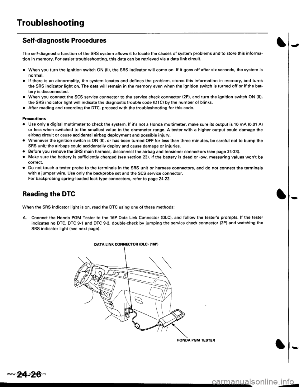
Reading the DTC
When the SRS indicator light is on, read the DTC using one of these methods;
A. Connect the Honda PGM Tester to the 16P Data Link Connector {DLC), and follow the tester's prompts. lf the tester
indicates no DTC, DTC 9-1 and DTC 9-2, double-check by jumping the service check connector (2P) and watching the
SRS indicator light (see next page).
HONDA PGM TESTER
DATA LINK CONNECIOR {DLCI {16P)
24-26
,1
www.emanualpro.com
Page 1332 of 1395
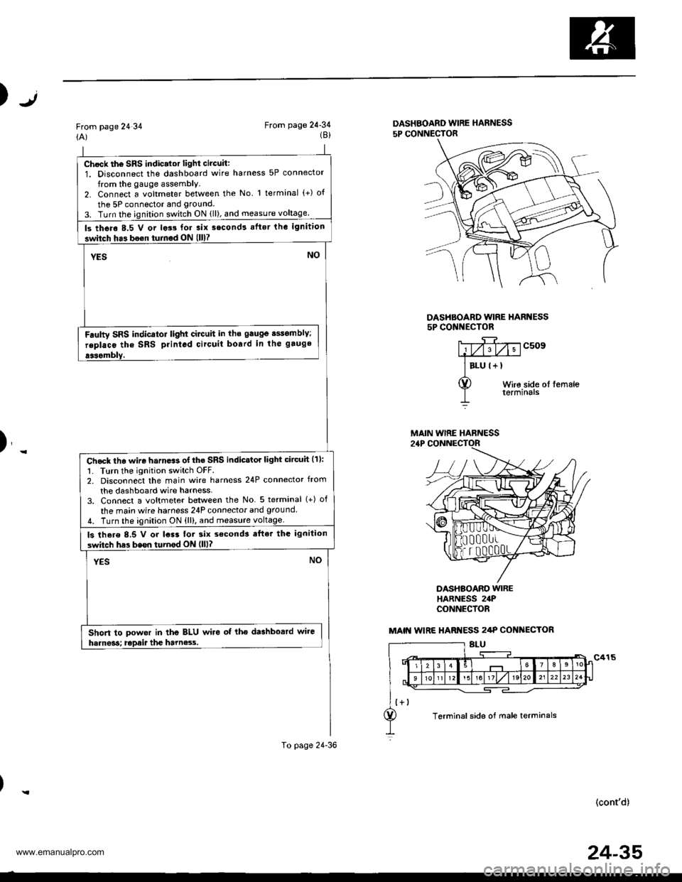
Chock th6 SRS indic.lor light circuit:1. Disconnect the dashboard wire harness 5P connector
from the gauge assembly.2. Connect a voltmeter between the No l terminal (+) o{
the 5P connector and grouncl.
3. Turn the ignition switch ON {ll), and measure voltage
ls thero 8.5 V or lats for 3ix second! aflsr the ignition
switch ha3 bo€n turnod ON (ll)7
YESNO
Fdulty SRS indicator light cilctlit in ths gauge sssomblY;
replaco tho SRS printod circuit board in the gauge
aasombly,
Chock th6 wire harn.$ of the SRS indicstor light circuh (11:
1. Turn the ignition switch OFF.2. Disconnect the main wire harness 24P connector from
the dashboard wire harness-3. Connect a voltmeter between the No 5 terminal (+) of
the ma;n wire harness 24P connecior and ground
4. Turn the ignition ON {ll), and measure voltage.
ls there 8,5 V or l€r3 tor six s€cond3 efter the ignilion
switch has bssn turnod ON llll?
YESNO
Short to powor in the BLU wire of tho dashbosrd wire
harne3s; Epait the harne3.s.
To page 24-36
Jt)
From page 24 34(A)From page 24-34(8)DASHBOARD WIRE HARNESS
5P CONNECTOR
DASHBOARD WIRE HARI{ESS5P CONI{ECTOR
c509
Wire side ol femaleterminals
)_
DASHBOARO WIREHARNESS 24PCONNECfOR
(cont'd)
MAIN WIRE HARNESS
MAIN WIRE HARI{ESS 2/tP COI{ ECTOR
Terminal side of male terminals
24-35
www.emanualpro.com
Page 1333 of 1395
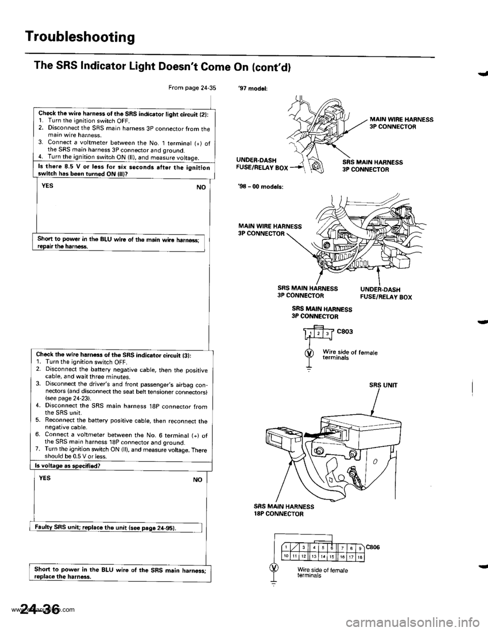
Troubleshooting
From page 24-35
Check lhe wire harness otthe SRS indicator light circuit l2l:L Turn the ignitjon switch OFF.2. Disconnect the SRS main harness 3p connector from themain wire harness.3. Connect a voltmeter between the No. I terminal (+) ofthe SRS main harness 3P connector and qround.4. Turn the ignition switch ON (ll), and measure voltaqe.
ls there 8.5 V o. less tor six seconds atter the ignitionswitch has been turned ON
Short to power in th€ BLU wire of the main wiro halno3s;
Check th€ wire hahess of th6 SRS indicator ci.cuit {31:1. Turn the ignition switch OFF.2. Disconnect the battery negative cable, then the positivecable, and wait three minutes.3. Disconnect the driver's and front passenger,s airbag con-nectors {and disconnect the seat belt tensioner connectors}(see page 24-23).4. Disconnect the SRS main harness 18p connector from
5. Reconnect the battery positive cable, then reconnect thenegative cable.6. Connect a voltmeter between the No. 6 terminal (+) ofthe SRS main harness 'l8P connector and ground.7. Turn the ignition switch ON (ll), and measure voltage. Thereshould be 0.5 V or less.
Short to power in the BLU wire oI the SRS main harngas;
The SRS Indicator Light Doesn't Come On (cont,dl
'97 modol:
J
MAIN WIRE HARNESS3P CONNECTOR
UNDER.DASHFUSE/RELAY BOX
'98 - 00 models:
SRS MAIN HARN€SS3P CONNECTOR
MAIN WIRE HARNESS3P CONNECTOR
SRS MAIN HARNESS3P CONNECTOR
SRS MAIN HARNESS3P COI{NECTOB
FUSE/RELAY BOX
c803
SRS MAIN HARNESS18P CONNECTOR
24-36
www.emanualpro.com