spring HONDA CR-V 1998 RD1-RD3 / 1.G Manual Online
[x] Cancel search | Manufacturer: HONDA, Model Year: 1998, Model line: CR-V, Model: HONDA CR-V 1998 RD1-RD3 / 1.GPages: 1395, PDF Size: 35.62 MB
Page 735 of 1395
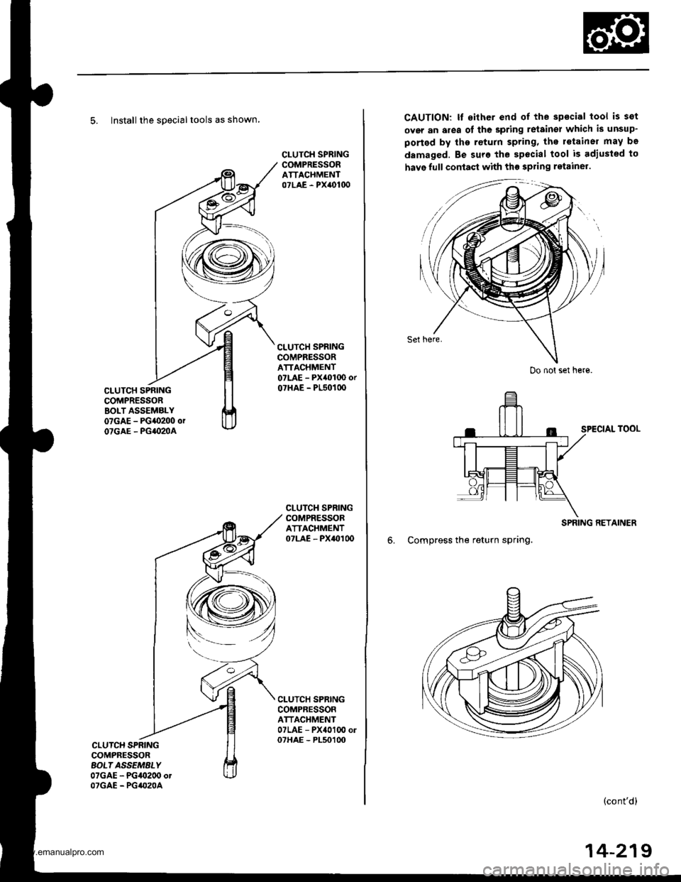
5. Install the specialtools as shown
CLUTCH SPRINGCOMPRESSORBOLT ASSEMALY07GAE - PG{0200 orOTGAE - PG|(IMA
CLUTCH SPRINGCOMPRESSORATTACHMENT07LAE - PX40100
CLUTCH SPRINGCOMPRESSORATTACHMENT07LAE - PX40100 orO?HAE - PL5O1OO
CLUTCH SPRINGCOMPRESSORATTACHMENT07LAE - PXaOI 0o
CLUTCH SPRINGCOMPRESSORATTACHMENT07LAE - PX4010O ol07HAE - PL50100CLUTCH SPRINGCOMPBESSORAOL| ASSEMALY07GAE - PG/9t200 otOTGAE - PG/(,20A
CAUTION: It sither end of the spscial tool is sot
over an area of the spring retain€l which is unsup'
ported by the return spring, the retainer may be
damaged. Be sure the special tool is adiusted to
have full contaqt with th€ spring ratainel.
Set here.
SPECIAL TOOL
SPRING RETAINER
6. Compress the return spring.
(cont'd)
Do not set here.
14-219
www.emanualpro.com
Page 736 of 1395
Clutch
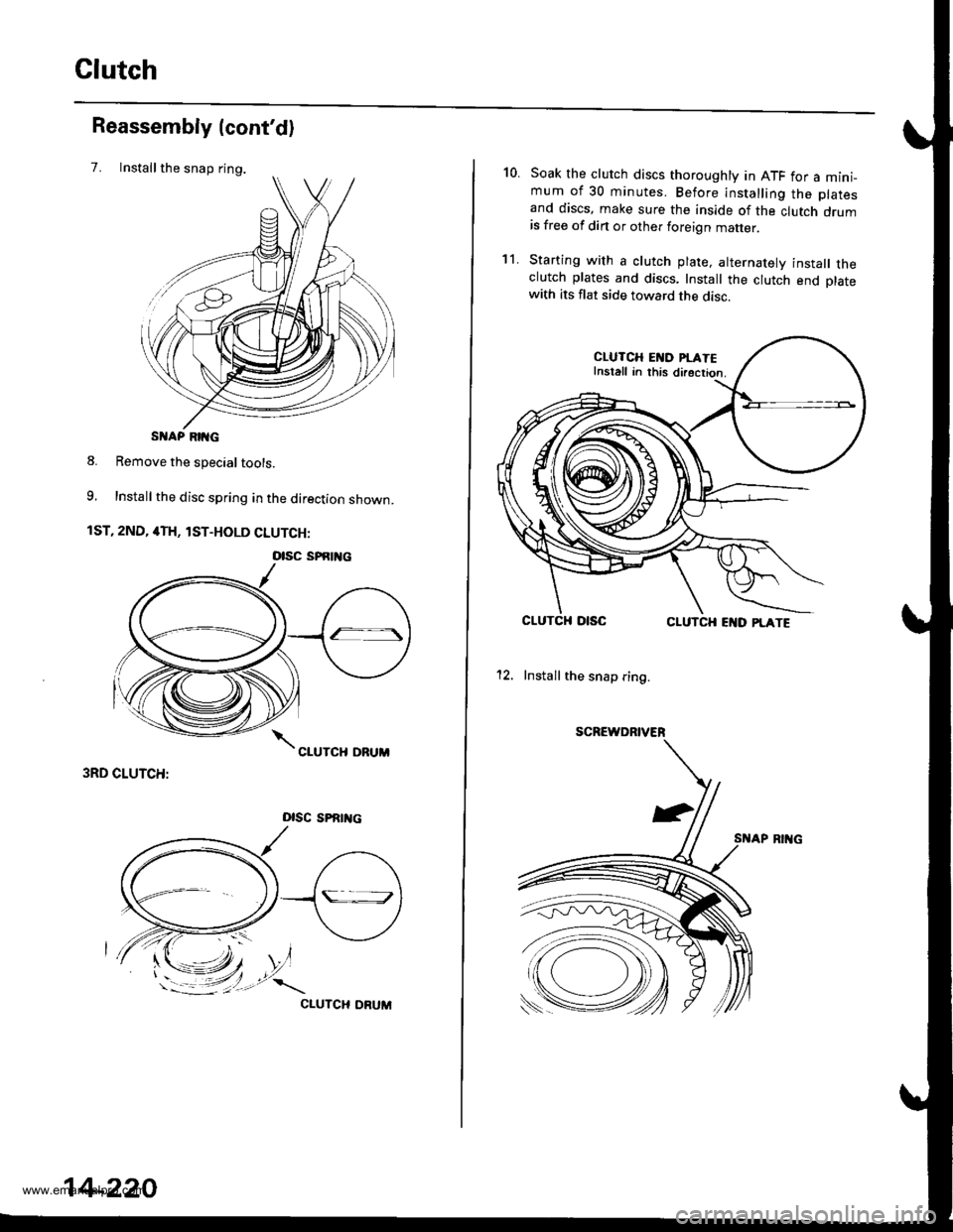
Installthe snap ring.
Reassembly (cont'd)
7.
S AP RIIG
8. Remove the special tools.
9, Install the disc spring in the direction shown.
1ST, 2ND, 4TH, lST-HOLD CLUTCH:
3RD CLUTCH:
Dlsc sPRrrtc
CIUTCH ORUM
otsc sPfitl{c
14-220
10.Soak the clutch discs thoroughly in ATF for a mini_mum of 30 minutes. Before installing the platesand discs, make sure the inside of the clutch drumis free of din or other foreign matter
Starting with a clutch plate, alternatelv install theclutch plates and discs. Install the clutch end platewith its flat side toward the disc.
CLUTCH EI{D PI.ATEInstall in this directior.
CLUTCHCLUTCH EI{D PLATE
12. Install the snap ring.
SCREWDRIVER
't1.
www.emanualpro.com
Page 740 of 1395
Differential
Differential Carrier Replacement
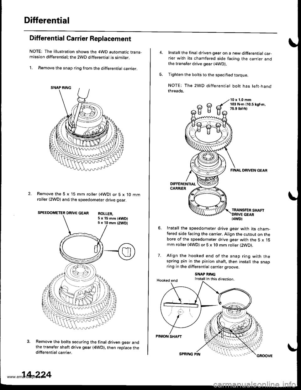
NOTE: The illustration shows the 4WD automatic trans-mission differential; the 2WD differential is similar.
1. Remove the snap ring from the differential carrier.
Remove the 5 x 15 mm roller (4WD) or 5 x 10 mmroller (2WDl and the speedometer drive gear.
SPEEDOMETER DRIVE GEAR RoI I FP
Remove the bolts securing the final driven gear andthe transfer shaft drive gear (4WD), then replace thedifferential carrier.
5 x 15 mm (/tWD)5 x 10 mm {2WDl
14-224
SPRING PINGROOVE
Install the final driven gear on a new differential car-rier with its chamfered side facing the carrier andthe transfer drive gear (4WD),
Tighten the bolts to the specified torque.
NOTE: The 2WD differentiat bolt has left-handthreads,
10 x 1.0 mm103 N.m 110.5 kd.m,7s.9 rbr.ft)
7.
FINAL DRIVEN GEAR
TRANSFER SHAFT
Install the speedometer drive gear with its cham-fered side facing the carrier. Align the cutout on thebore of the speedometer drive gear with the 5 x 15mm roller (4WD) or 5 x 10 mm roller (2WD).
Align the hooked end of the snap ring with thespring pin in the pinion shaft. then install the snaoring in the differential carrier groove
SNAP RINGInstall in this direction.Hooked end
PINION SHAFT
{4WDl
www.emanualpro.com
Page 751 of 1395
Disassembly
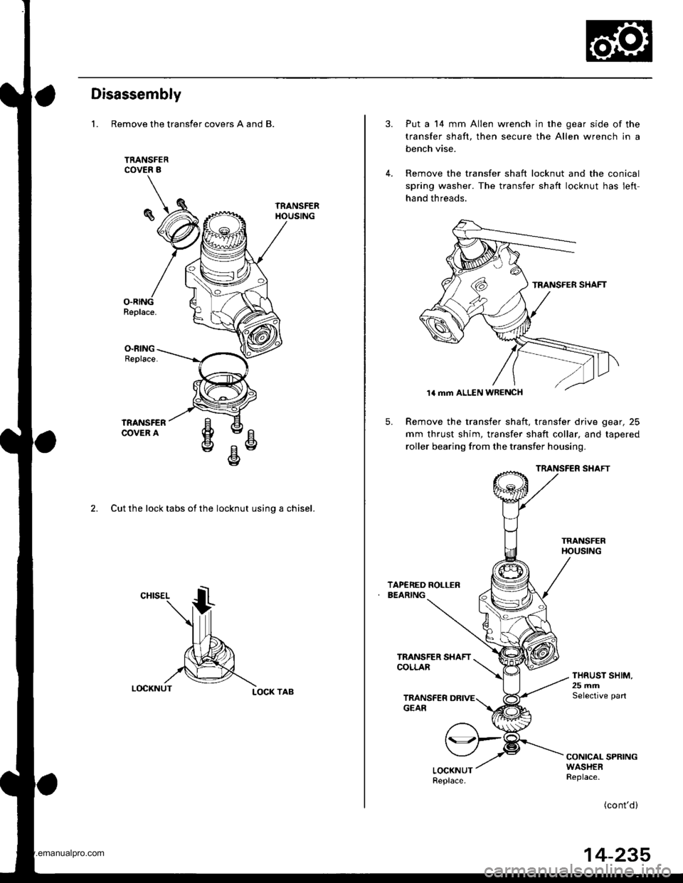
1. Remove the transfer covers A and B.
2. Cut the lock tabs of the locknut usino a chisel.
LOCK TAB
5.
Put a 14 mm Allen wrench in the gear side of the
transfer shaft, then secure the Allen wrench in a
bench vise.
Remove the transfer shaft locknut and the conical
spring washer. The transfer shaft locknut has left
hand threads.
Remove the transfer shaft, transfer drive gear, 25
mm thrust shim, transfer shaft collar, and tapered
roller bearing from the transfer housing.
TRANSFER SHAFT
THRUST SHIM,25 mrnSelective part
CONICAL SPRINGWASHERReplace.
(cont'd)
1a mm ALLEN WRENCH
14-235
www.emanualpro.com
Page 752 of 1395
Transfer Assembly
Disassembly (cont'd)
7.
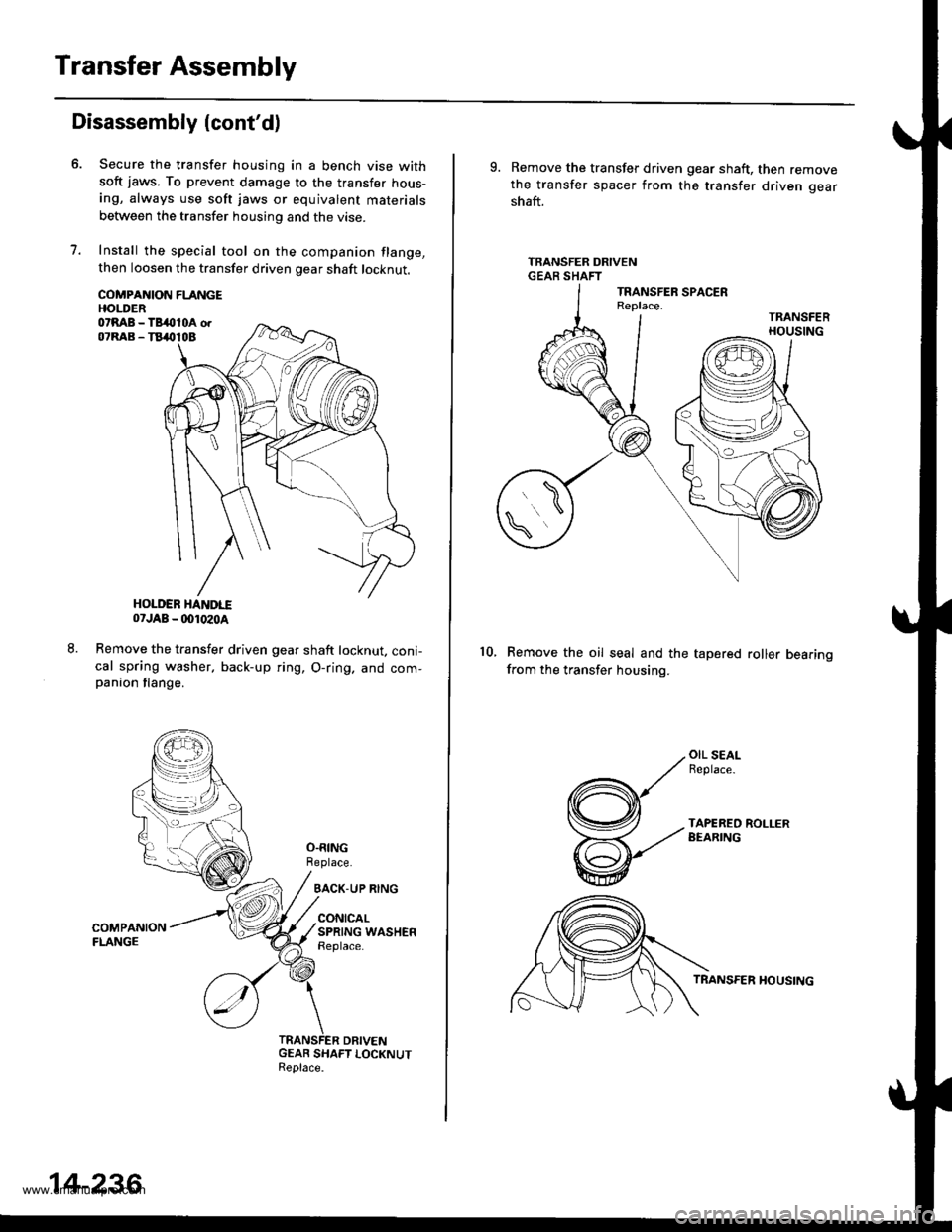
Secure the transfer housing in a bench vise withsoft iaws. To prevent damage to the transfer hous-ing, always use soft jaws or equivalent materials
between the transfer housing and the vise.
Install the special tool on the companion flange,then loosen the transfer driven gear shaft locknut.
COMPANION FLANGEHOI.DER07RAB - TB4lll0A orOTRAB - TB&TOB
HOLDER HAITDI..E07JAB _ (x)1020a
Remove the transfer driven gear shaft locknut, coni-cal spring washer, back-up ring, O-ring. and com-panion flange.
O.RINGReplace.
BACK-UP RING
CONICALSPRING WASHENReplace.
GEAR SHAFT LOCKNUTReplace.
14-236
9. Remove the transfer driven gear shaft, then removethe transfer spacer from the transfer driven gear
shaft.
TRANSFER DRIVENGEAR SHAFT
Remove the oil seal and the tapered roller bearingfrom the transfer housing.
10.
OIL SEALFeplace-
TAPEREO ROLLERBEARING
TRANSFER HOUSING
www.emanualpro.com
Page 757 of 1395
Transfer Gear Bscklash Inspection and Transfer Gear
Tooth Contact Inspection
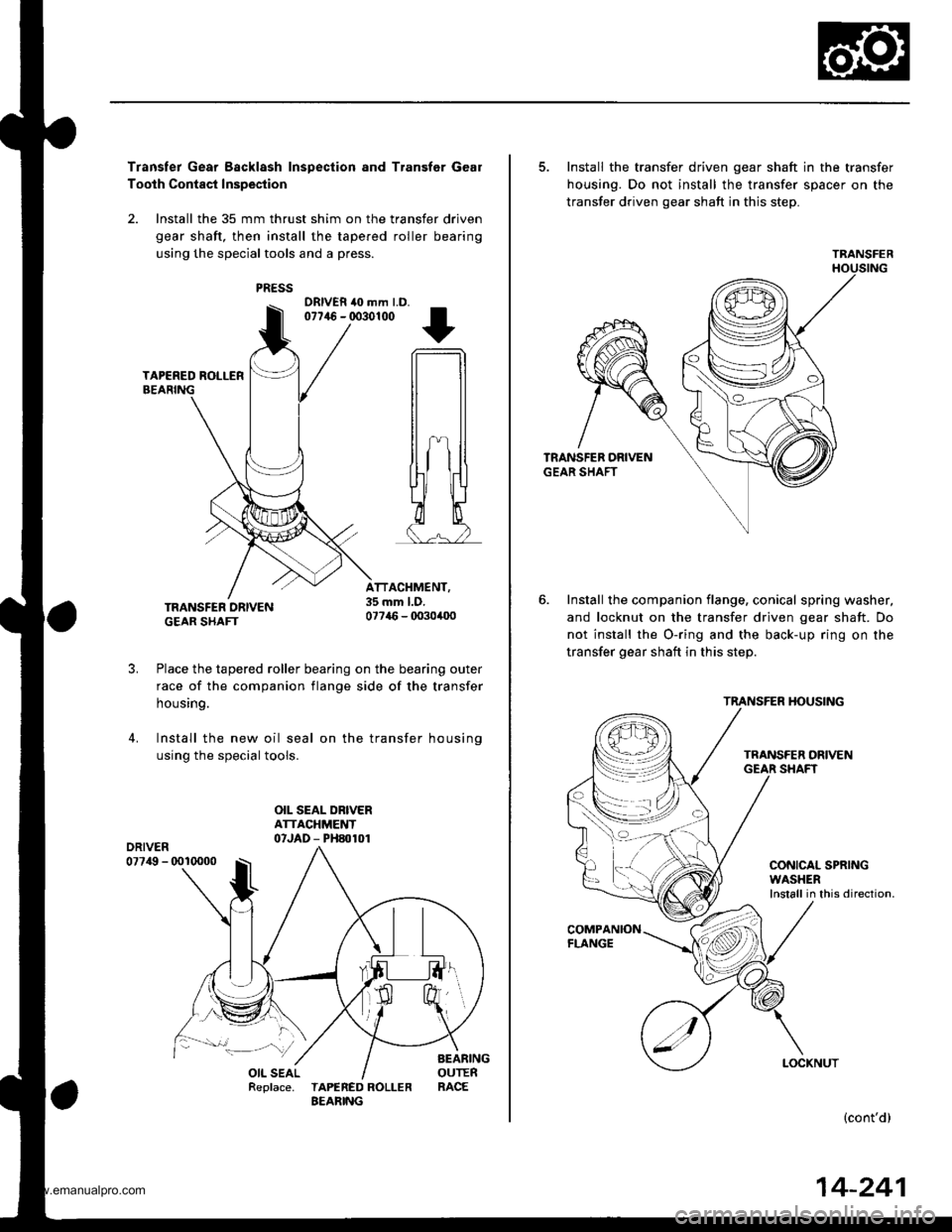
2. Install the 35 mm thrust shim on the transfer driven
gear shaft, then install the tapered roller bearing
using the special tools and a press.
DRIVER {0 mm LD.077146 - 0030100
TRANSFER DRTVEN ;;.GEAR SHAFT u, 745 - 0O304O0
Place the tapered roller bearing on the bearing outer
race of the companion flange side of the transfer
housrng.
Install the new oil seal on the transfer housing
using the special tools.
OIL SEAL DRIVERATTACHMENT07JAD - PH80101
5. Install the transfer driven gear shaft in the transfer
housing. Do not install the transfer spacer on the
transfer driven gear shaft in this step.
Install the companion flange, conical spring washer,
and locknut on the transfer driven gear shaft. Do
not install the O-ring and the back-up ring on the
transfer gear shaft in this step.
6.
COMPANIONFLANGE
{cont'd)
TRANSFER
TRANSFER HOUSING
14-241
www.emanualpro.com
Page 758 of 1395
Transfer Assembly
Reassembly (cont'd)
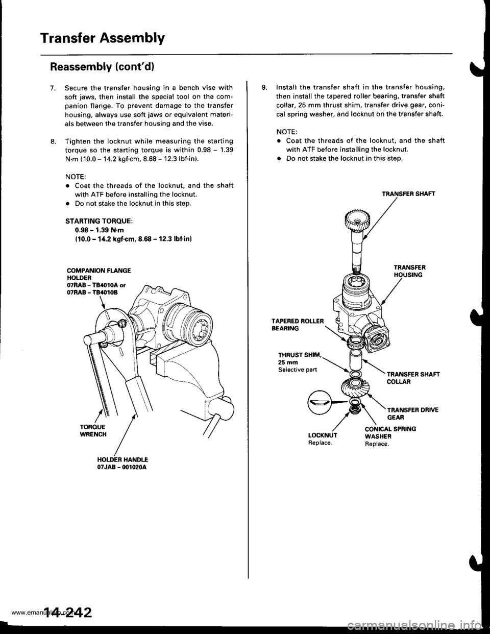
7.Secure the transfer housing in a bench vise with
soft jaws, then install the special tool on the com-
panion flange. To prevent damage to the transfer
housing, always use soft jaws or equivalent materi-
als between the transfer housing and the vise.
Tighten the locknut while measuring the starting
torque so the starting torque is within 0.98 - '1.39
N.m (10.0 - 14.2 kgf.cm, 8.68 - 12.3 lbnin).
NOTE:
Coat the threads of the locknut, and the shaft
with ATF before installing the locknut.
Do not stake the locknut in this step.
STARTING TOROUE:
0.98 - 1.39 N.m
{10.0 - 14.2 kgrf.cm,8.68 - 12.3 lbf'inl
COMPANION FLANGEHOLDER
07JAB - @1020A
14-242
9. Install the transfer shaft in the transfer housing,
then install the tapered roller bearing, transfer shaft
collar.25 mm thrust shim, transfer drive gear, coni-
cal spring washer, and locknut on the transfer shaft.
NOTE:
. Coat the threads of the locknut. and the shaft
with ATF before installing the locknut.
. Do not stake the locknut in this step.
TRANSFER
THRUST SXIM,25 mmSelective pan
TRANSFER DRIVEGEAR
CONICAL SPRINGWASHERReplace.
www.emanualpro.com
Page 761 of 1395
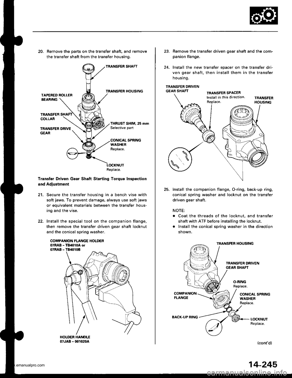
20. Remove the parts on the transfer shaft, and remove
the transfer shaft from the transfer housinq.
TRANSFER SHAFT
TRANSFER HOUSINGTAPEFED ROLLERBEARNG
TRANSFERCOLLAR
TRANSFER DRIVEGEAR
THRUST SHIM, 25 mmSelective pan
CONICAL SPRINGWASHERReplace.
Transf€r Driven Gear Shaft Starting Torque Inspsction
and Adjustment
21. Secure the transfer housing in a bench vise with
soft jaws, To prevent damage, always use soft jaws
or equivalent materials between the transfer hous-
ing and the vise.
22. Install the special tool on the companion flange,
then remove the transfer driven oear shaft locknut
and the conical spring washer.
COMPANION FLANGE HOLDER07RAB - TB,010A ol07RAB - TB,010B
Replace.
23. Remove the transter driven gear shaft and the com-
panion flange,
24. Install the new transfer spacer on the transfer dri-
ven gear shaft, then install them in the transfer
housrng.
TRANSFER DRIVENGEAR SHAFTTFANSFER SPACERlnstall in this direction.Replace.
25.Install the companion flange, O-ring, back-up ring.
conical spring washer and locknut on the transfer
driven gear shaft.
NOTE:
. Coat the threads of the locknut, and transfer
shaft with ATF before installing the locknut.
. Install the conical spring washer in the direction
shown,
TRANSFER HOUSING
O.RINGReplace.
CONICAL SPRINGWASHERReplace.
LOCKNUTReplace.
(cont'd)
BACK.UP RING
14-245
www.emanualpro.com
Page 762 of 1395
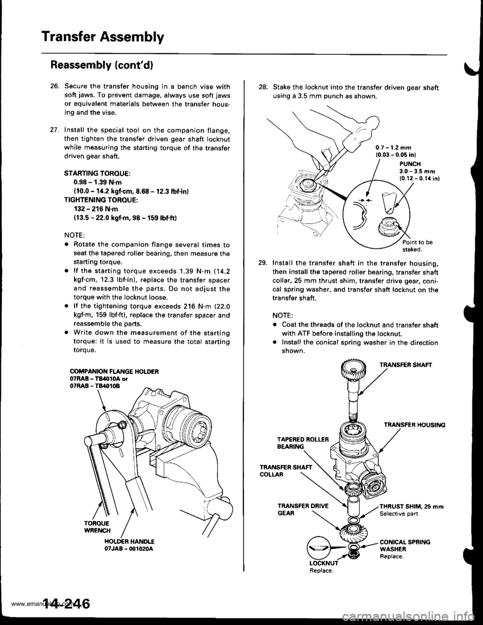
Transfer Assembly
Reassembly (cont'd)
Secure the transfer housing in a bench vise with
soft jaws. To prevent damage, always use soft jaws
or equivalent materials between the transfer hous-
ing and the vise.
Install the special tool on the companion flange,
then tighten the transfer driven gear shaft locknut
while measuring the starting torque of the transfer
driven gear shaft.
STARTING TOROUE:
0.s8 - 1.39 N.m
{10.0 - 14.2 kgf.cm,8.68 - 12.3 lbf.in)
TIGHTENING TOROUE:
132 - 216 N.m
{13.5 - 22.0 kgf.m, 98 - 159 lbf.ft)
NOTE;
. Rotate the companion flange several times to
seat the tapered roller bearing, then measure the
starting torque,
. lf the starting torque exceeds 1.39 N.m (14,2
kgf.cm, 12.3 lbf.in), replace the transfer spacer
and reassemble the parts. Do not adjust the
torque with the locknut loose.
. lf the tightening torque exceeds 216 N.m (22.0
kgf.m, 159 lbf'ft), replace the transfer spacer and
reassemble the parts.
. Write down the measurement of the starting
torque: it is used to measure the total starting
rorque.
COi'PANIOI{ FLANGE HOLDER07MB - TBi(tloA otO'RAB - TB,.|}IOB
TOFOUEWRENCH
HOLDER HANDLE07JAB - 001020A
27.
14-246
28. Stake the locknut into the transfer driven gear shaft
using a 3,5 mm punch as shown.
0.7 - 1.2 mm{0.03 - 0.05 inl
PUNCH3.0 - 3.5 mm10.12 - 0.1{ inl
Point to bestaked.
29. Install the transfer shaft in the transfer housing,
then install the tapered roller bearing, transfer shaft
collar,25 mm thrust shim, transter drive gear, coni-
cal spring washer, and transfer shaft locknut on the
transfer shaft,
NOTE:
. Coat the threads of the locknut and transler shaft
with ATF before installing the locknut.. Install the conical spring washer in the direction
snown.
TRANSFER SHAFT
TRANSFER HOUSII{G
THRUST SHIM. 25 mrt|Selective part
CONICAL SPRINGWASHERReplace.
\t)t--/./
.,.-,.,\
Replace.
www.emanualpro.com
Page 766 of 1395
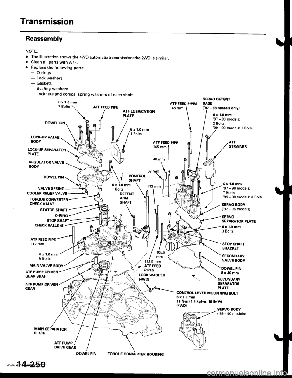
Transmission
Reassembly
NOTE:
. The illustration shows the 4WD automatic transmission; the 2WD is similar.. Clean all parts with ATF.. Replace the following parts:- O-rings- Lock washers- Gaskets- Sealing washers- Locknuts and conical spring washers of each shaft
ATF FEED PIPE
/
ATF FEED PIPES145 mm
SERVO DETENTBASE(37 -98 modeb onlylATF LUBRICATIONPLATE6x1.0mm
2 Bolts'99 - 00 models: 1 Bolts
LOCK.UP VALVEBODY
LOCK.UP SEPARATORPLATE
REGULATOR VALVEBODY
DOWEL PIN
DOWEL PIN
VALVE SPRING
STATOR SHAFT
'-
'112mmll,
rlT
ATFSTRAINER
40 mm
j coNrRoLI SHAFT
COOLER BELIEF VALVE
TOROUE CONVERTERCHECK VALVE
6x1.0mm18olts
DETENTARMSHAFT
6x1,0mm'97 - 98 models:7 Bolts'99 - 00 models:8 Bolts
SERVO BODY('97 - 98 models)
SERVOSEPARATOR PLATE
6x1.0mm3 Bolts
STOP SHAFTBRACKET
SECONDARYVALVE BODY
OOWEL PIN8x40mm
O.RING
STOP SHAFTCHECK BALLS 18'
ATF FEED PIPE112 mm
6x1.0mm5 Eolts
ATF PUMP DRIVENGEAR SHAFT
ATF PUMP DRIVEN
MAIN SEPARATORPLATE
MAIN VALVE EOOY
SECONDARYSEPARATOR
d---.- PLATE--.- CONTROL I.EVER MOUNTING BOLT6x1.0ftm14 N.m (1.4 kgt.m, 10 tbf.ft)(4WD)SERVO BODY('99 - 00 models)
ATF PUMP
6x1.0mm
ATF FEEO PIPE
) / 105.8
/,,!.,::(./ afF FEEO,/ ptpEs
EP,---!ir{+*a r
fpffi4 i
x*hi
_ \zl
14-250
DRIVE GEAR
DOWEL PINTOBOUEHOUSING
www.emanualpro.com