HONDA INTEGRA 1994 4.G Workshop Manual
INTEGRA 1994 4.G
HONDA
HONDA
https://www.carmanualsonline.info/img/13/6067/w960_6067-0.png
HONDA INTEGRA 1994 4.G Workshop Manual
Page 46 of 1413
Engine Removal/lnstallation
Special Tools ........ .".....5-2
Engine Removal/lnstallation ..."........ 5-3
Mount/Bracket Torque ..' 5-16
Page 51 of 1413
Engine Removal/lnstallation
(cont'd)
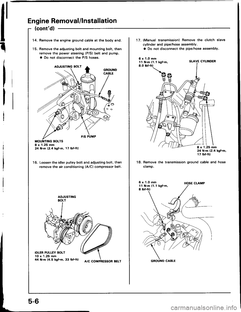
14.Remove the engine ground cable at the body end.
Remove the adiusting bolt and mounting bolt, then
remove the power steering (P/Sl belt and pump.
a Do not disconnect the P/S hoses.
8 r 1.25 mm24 N.m (2.4 kgf.m. 17 lbl.ftl
6. Loosen the idler pulley bolt and adjusting bolt, then
remove the air conditioning (A/C) compresso. belt.
IDLER PULLEY BOLT10 x 1.25 mm44 N.m 14.5 kgt.m, 33 lbl.ftl
5-6
A/C COMPRESSOR BELT
17. (Manusl transmission) Remove the clutch slave
cylinder and pipe/hose assembly.
a Do not disconnect the pipe/hose assembly.
6 x 1.O rl|mll N.m { 1.1 kgt.m,SLAVE CYLINDER
8.0
8 x 1.25 mm24 N.m {2.4 kgl.m,17 lbt.ftl
18. Remove the transmission ground cable and hose
cramp.
6 x 1.O mm1l N.m 11 ,1 kgt.m,I tbt.ftl
Page 56 of 1413
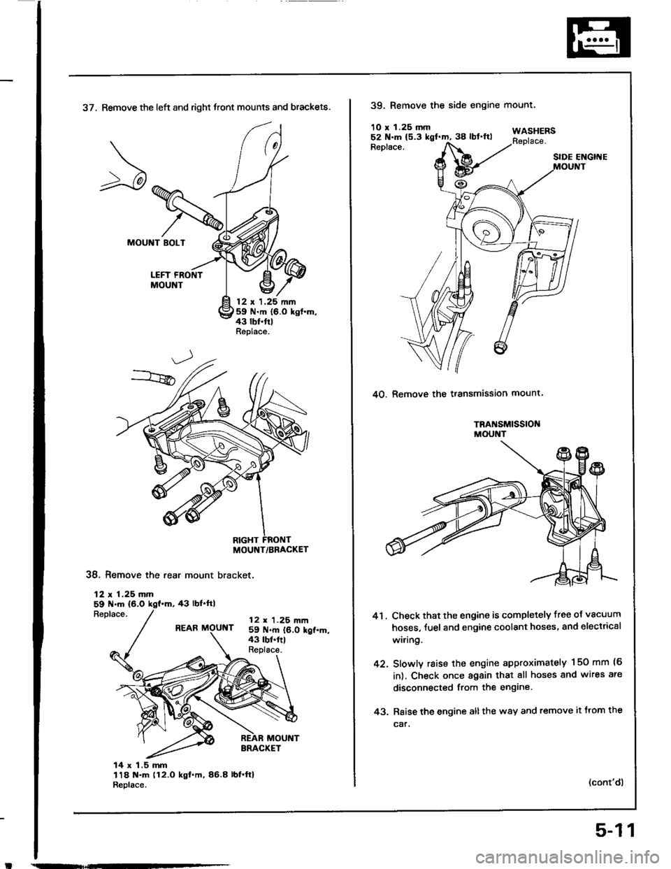
37, Remove the left and right front mounts and brackets.
MOUNT BOLT
LEFT FRONTMOUNT
12 t 1.25 nn59 N.m {6.0 kgt.m,43 lbf.trlReplace.
38. Remove the rear mount bracket,
12 r 1.25 mm59 N.m (6.0
Replace.43 rbf.ftl
REAR MOUNT12 r 1.25 m|n59 N.m {6.0 kgt.m,43 tbt.frlReplace.
14 x 1.5 mm118 t{.m (12.O kgt.m,86.8 lbl.ft}R6place.
MOUNT/BRACKET
39. Remove the side engine
10 r 1.25 mm
mounr.
WASHERSReplace.Replace.SIDE ENGIITE
40. Remove the transmission mount
TRA SM|SS|OI{MOUNT
41. Check that the engine is completely free of vacuum
hoses, fuel and engine coolant hoses, and electrical
wi.ing.
42. Slowly raise the engine approximately 150 mm (6
in), Check once again that all hoses and wires are
disconnected from the engine
43. Raise the engine all the w8y and remove it trom the
car.
(cont'dl
5-11
Page 57 of 1413
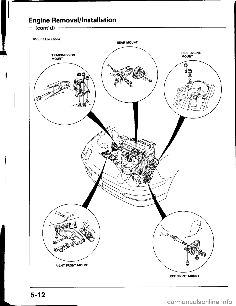
Engine Removal/lnstallation
SIDE ENGITIEMOUNT
5-12
Page 58 of 1413
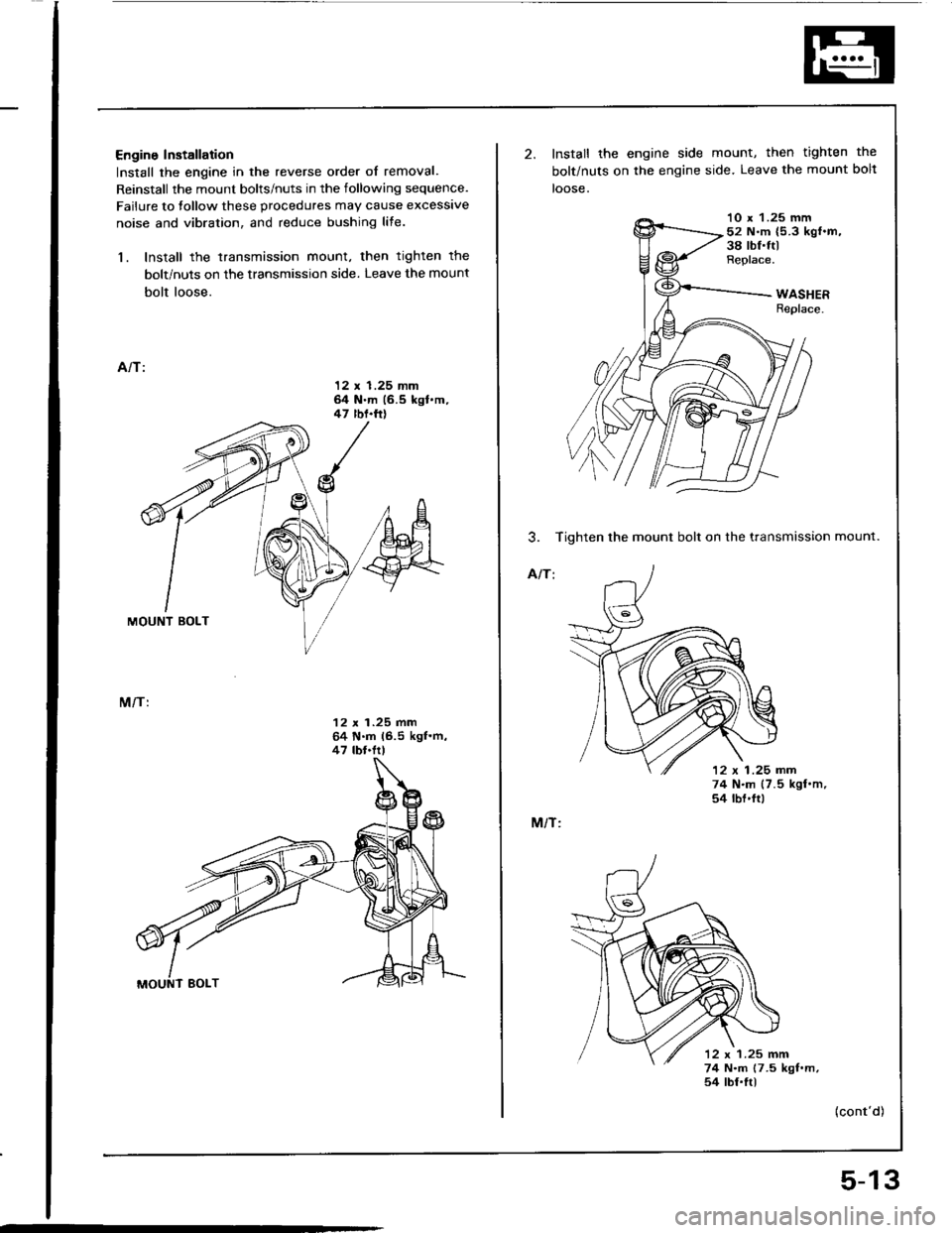
Engine Installation
Install the engine in the reverse order of removal.
Reinstall the mount bolts/nuts in the following sequence.
Failure to tollow these procedures may cause excessive
noise and vibration, and reduce bushing life.
1. Install the transmission mount, then tighten the
bolt/nuts on the transmission side. Leave the mount
bolt loose.
A/T:
12 x 1.25 mm64 N.m (6.5 kgt.m,47 rbf.ft)
M/T:
12 x 1.25 mm64 N.m 16.5 kgl.m,47 tbt.frl
Install the engine side mount, then tighten the
bolt/nuts on the engine side. Leave the mount bolt
loose.
10 x 1.25 mm52 N.m {5.3 kgf.m,38 rbf.ItlReplace.
3. Tighten the mount bolt on the transmission mount.
A/T:
12 x 1 .25 nn
M/T:
74 N.m (7.5 kgl.m,54 rbf'ftt
12 x 1.25 mm74 N.m (7.5 kgt.m,54 tbt.ftl
{cont'd)
5-13
Page 59 of 1413
Engine Removal/lnstallation
.tE
m'
(cont'dl
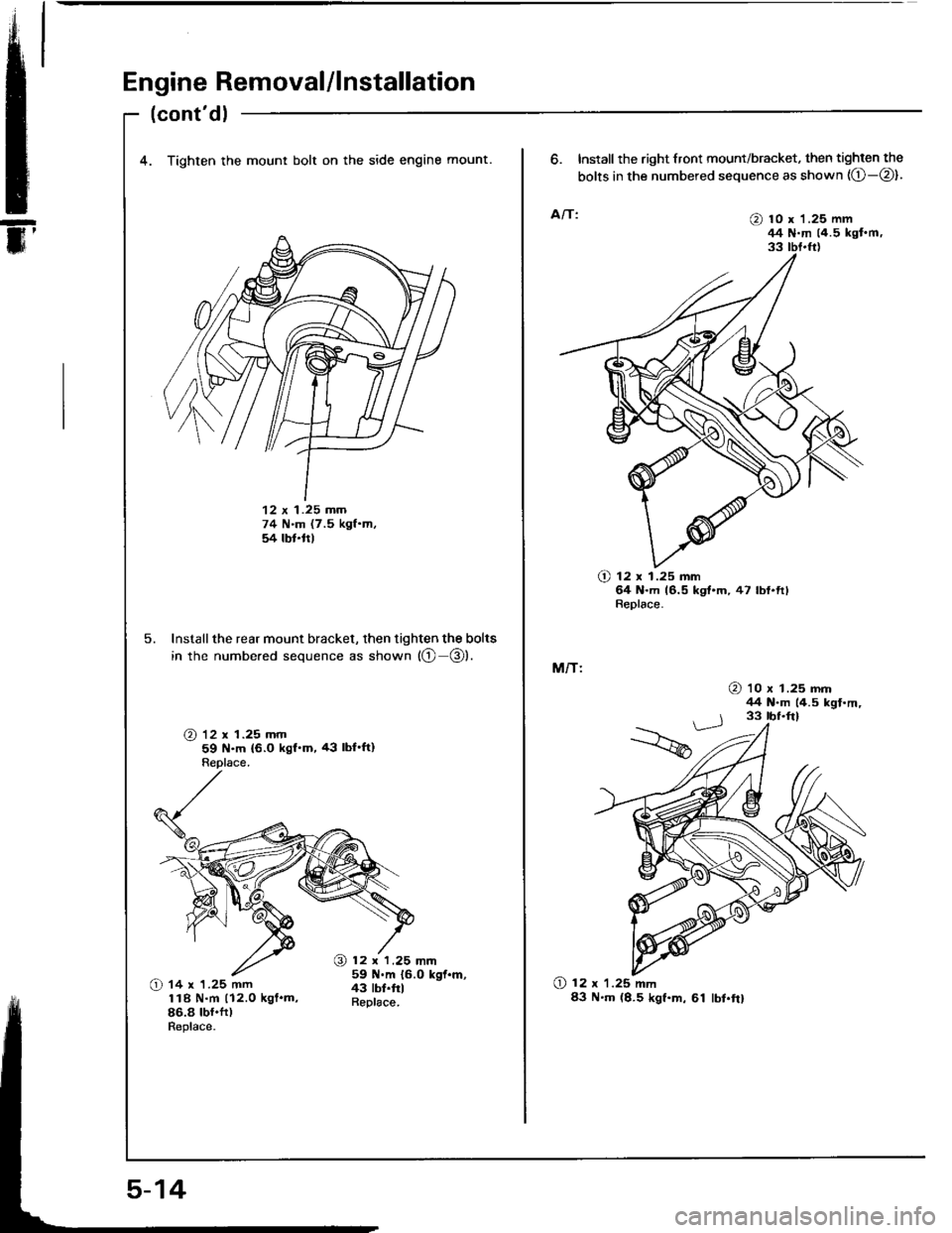
4. Tighten the mount bolt on the side engine mount.
12 x 1.25 mm74 N.m (7.5 kgf.m,54 lbt.ttl
5. Install the rear mount bracket, then tighten the bolts
in the numbered sequence as shown {@ @).
@ 12 x 1.25 mm59 N.m {6.0 kgf'm, 43 lbl'It)Replace.
12 r 1.25 mm59 .m 16.0 kgl.m,
6. Install the right front mount/bracket, then tighten the
bolts in the numbered sequence as shown (O-@).
A/T:@ 10 x '1.25 mm44 N.m (4.5 kgt'm,33 tbt.fr)
O 12 x 1.25 mm64 N.m 16.5 kgt.m,47 lbf.ftlReplace.
M/T:
O 12 x 1.25 mm83 N'm (8.5 kgf.m, 61 lbt.frl
@ '10 x 1.25 mm44 N-m (4.5 kgf.m,
Page 62 of 1413
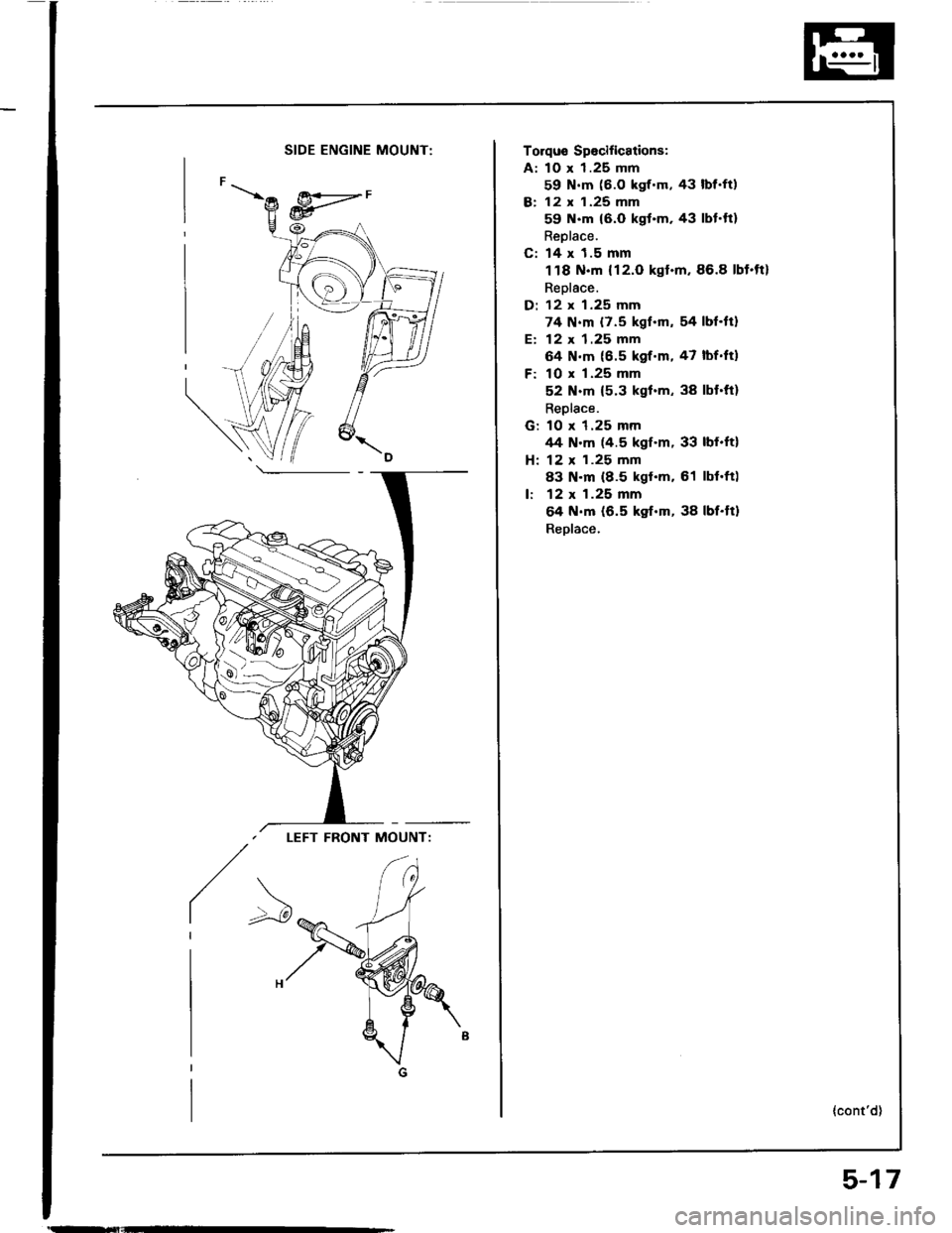
SIDE ENGINE MOUNT:
LEFT FRONT MOUNT:
/>
Torqus Spocifications:
A: 10 x 1.25 mm
59 N.m (6.O kgf.m, 43 lbf.ft)
B: 12 x 1.25 mm
59 N.m {6.0 kgt.m. 43 lbt.ft}
Reolace.
C: 14 x 1.5 mm
118 N.m {12.O kgt.m,86.8 lbt.tt}
Replace.
D: 12 x 1.25 mm
74 N.m {7.5 kgf.m, 54 lbf.tt}
E: 12 x 1.25 mm
64 N.m (6.5 kgf.m, 47 lbf.ftl
F: 10 x 1.25 mm
52 N.m {5.3 kgl.m, 38 lbt.ft}
Replace.
G: 10 x 1.25 mmrt4 N.m (4.5 kgf.m, 33 lbf.ft)
H: 12 x 1.25 mm
83 N.m (8.5 kgt.m. 61 lbl.ft)
lr 12 x 1.25 mm
64 N.m (6.5 kgf.m, 38 lbf.tt)
Reolace.
{cont'd)
5-17
Page 63 of 1413
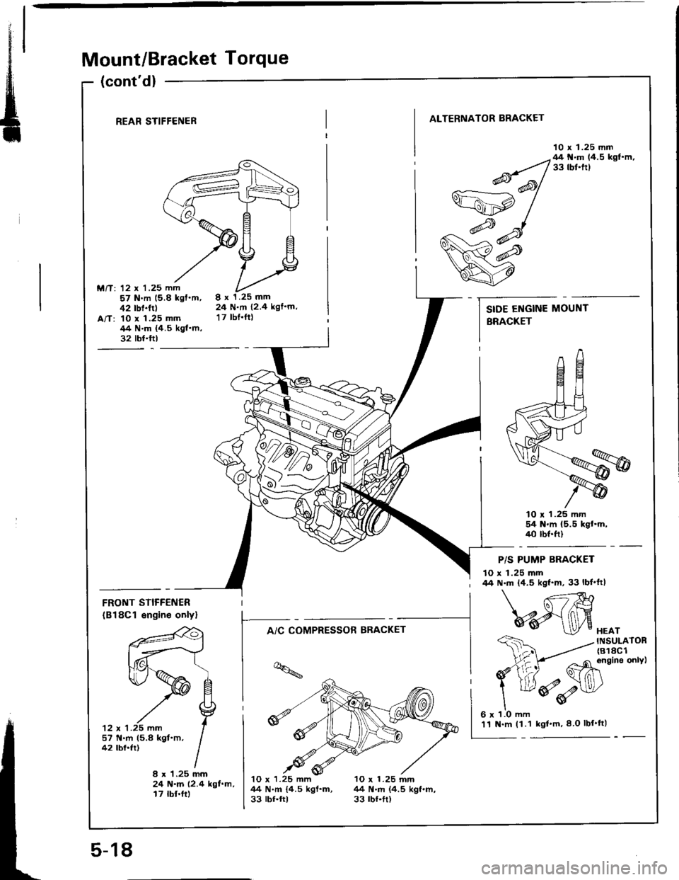
Mount/Bracket Torque
(cont'd)
REAR STIFFENER
M/T: 12 x '1.25 mm57 N.m 15.8 kgf'm,42 rbf.ft)A/T: 10 x 1.25 mm/14 N.m {4.5 kgf.m,32 tbt.ftl
ALTERNATOR BRACKET
10 x 1.25 mm
8x1.25mm24 N.m 12.4 kgf'm,
17 tbt.ftt
lO r 1.25 mm54 N'm (5.5 kgl.m,40 tbf.ft)
FRONT STIFFENER
(B18Cl engin€ onlyl
'12 x 1 .25 mm
f--^,c*;"*".*-
t-*i;
lq
I -4M
- Ghinein"onvt
ddv
HEATINSULATOR(818C1
P/S PUMP BRACKET
10 x 1.25 mm44 N.m (4.5 kgf'm, 33 lbf'ft|
57 N.m 15.8 kgt.m,42 tbf.fr)
8 x 1.25 mm24 N.m (2.4 kgf.m,17 tbf.ft)
10 x 1.25 mm 10 x 1.25 mnl44 N.m {4.5 kgf.m, 44 N.m (4.5 kgf.m,33 rbr.ftt 33 rbr.tt)
SIDE ENGINE MOUNT
BRACKET
5-18
'11 N.m (1.1 kgl'm,8 O lbf'tt)
Page 80 of 1413
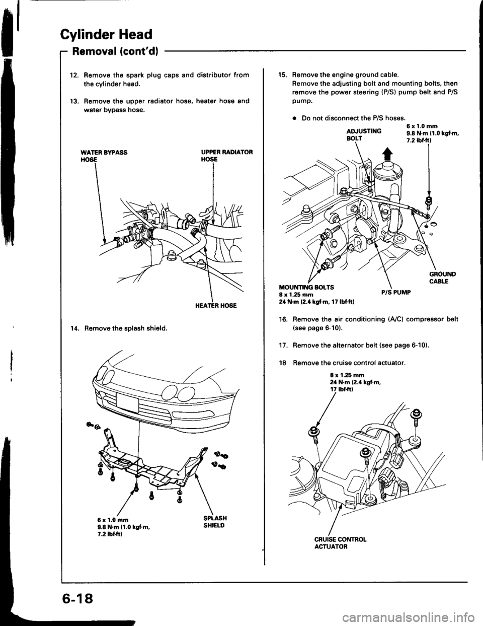
Cylinder Head
Removal (cont'dlI
12.R€move the spark plug caps and distributor from
the cvlinder head.
Remove the upper radiator hose, heater hose and
water bypass hose.
UPPER RAI'IAYOR
14. Remove th6 solash shield.
WATER BYPASS
9.8 N.m {1.0 kgt m.t.2 tbr.frt
sHtEut
15. Remove the engine ground cable.
Remove the adjusting bolt and mounting bolts, then
remove the power steering (P/S) pump belt 8nd P/S
pump.
. Do not disconnect the P/S hoses.
6x1.0mmADJUSTINGBOLT9.8 N.m 11.0 tgfm,7.2 tbf.ftl
8 x 1.25 mm24 .m (2.akstm, 17lbf.ftl
P/S PUMP
Remov€ the air conditioning (Ay'Cl compressor(see pags 6-10).
R€move the alternator belt (see page 6-10).
Ramove the cruise control actuator.
8 x 1.25 mm2a N.m 12.4 kgt m,
belt
17.
t8
ACTUATOR
Page 81 of 1413
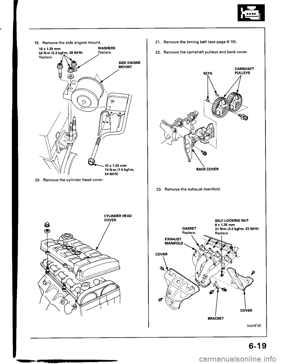
52 N.m (5.3 kgt'm, 38 lbf'ft)
19. Remove the side engine mount.
10 x 1.25 mm
20. Remove the cylinder head cover.
WASHERS
SIDE ENGINEMOUNT
12 x 1.25 mm74 N.m {7.5 kgf.m,5{ rbtftl
CYLINDEB HEAD
Remove the timing belt (see page 6-10).
Remove the camshaft pulleys and back cover.
23. Remove the exhaust manifold.
SELF.LOOKING NUT8 x 1.25 mm
BACK COVER
BRACKET
(cont'd)
6-19
