lock HONDA INTEGRA 1994 4.G Workshop Manual
[x] Cancel search | Manufacturer: HONDA, Model Year: 1994, Model line: INTEGRA, Model: HONDA INTEGRA 1994 4.GPages: 1413, PDF Size: 37.94 MB
Page 1247 of 1413
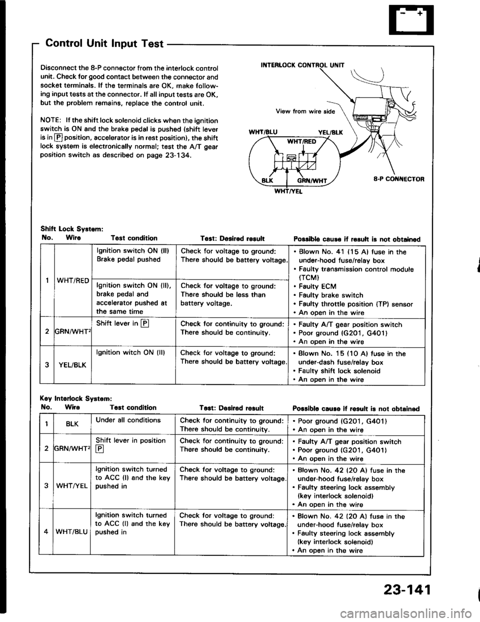
Control Unit Input Test
Oisconnect the 8-P connector from the interlock control
unit. Check for good contact between the connector and
socket terminals. lf the terminals 8re OK, make Iollow-
ing input tests at the connector. lf all input tests are OK,
but the problem remains, replace the cont.ol unit,
NOTE: lf the shilt lock solenoid clicks when the ignition
switch is ON and the brake pedal is pushed (shift tever
is in lfl position, accelerator is in rest position), the shiftlock system is electronically normal; test the A/T gear
positaon switch as described on page 23- 134.
Shift Lock Sy.tem:
No, Wlr6 Tost condition
Koy Intodock Systam:
No. WireT6st condition
Tost: Dosired resultPossiblo cause if rssuh is not obtainod
T6st: Desiled reaultPossible caure if rosult is not obtainsd
'I
lgnition switch ON (ll)
Brake pedal pushedCheck for voltage to ground:
There should be bsttery voltage
Blown No. 41 (15 A) fuse in the
under-hood fuse/relay box
Faulty transmission control module(TCM}
Faulty ECM
Faultv brake switch
Faulty throftle position lTP) sensor
An oDen in the wire
wn t/hEulgnition switch ON
brske pedal and
accelerator pushed
the same time
I [),
at
Check for voltage to ground:
There should be less than
battery voltage.
GRN^/vHT'
Shift lever in @Check lol continuity to ground:
There should be continuity.
Faulty A/T gear position switch
Poor ground {G201, G401}
An oDen in the wire
YEL/BLK
lgnition witch ON (lllCheck for voltage to ground:
There should be battery voltage
Blown No. 15 (10 A) luse in the
under-dash fuse/relay box
Faulty shift lock solenoid
An oDen in the wire
BLKUnder all conditionsCheck for continuity to ground:
There should be continuitv.
. Poor ground (G2O1, G4O1). An ooen in the wire
2
Shift lever in position
E
Check for continuity to ground;
Ther€ should be continuity.
Faulty A/T gear position swirch
Poor ground (c2O1 , G4O1)
An oDen in the wire
3WHTAYEL
lgnition switch tu.ned
to ACC (ll 8nd the keypushed in
Check for voltage to ground:
There should be battery voltage
Bfown No. 42 l2O Al fuse in the
under-hood tuse/relay box
Faulty steering lock assembly(kev interlock solonoid)
An oDen in the wire
4WHT/BLU
lgnition switch turned
to ACC (ll and the keypushed in
Check tor voltage to ground:
There should be batery voltage,
Bfown No. 42 l2O Al fuse in the
under-hood fuse/relav box
Faulty steering lock assembly(key interlock solenoid)
An oDen in the wire
23-141
Page 1248 of 1413
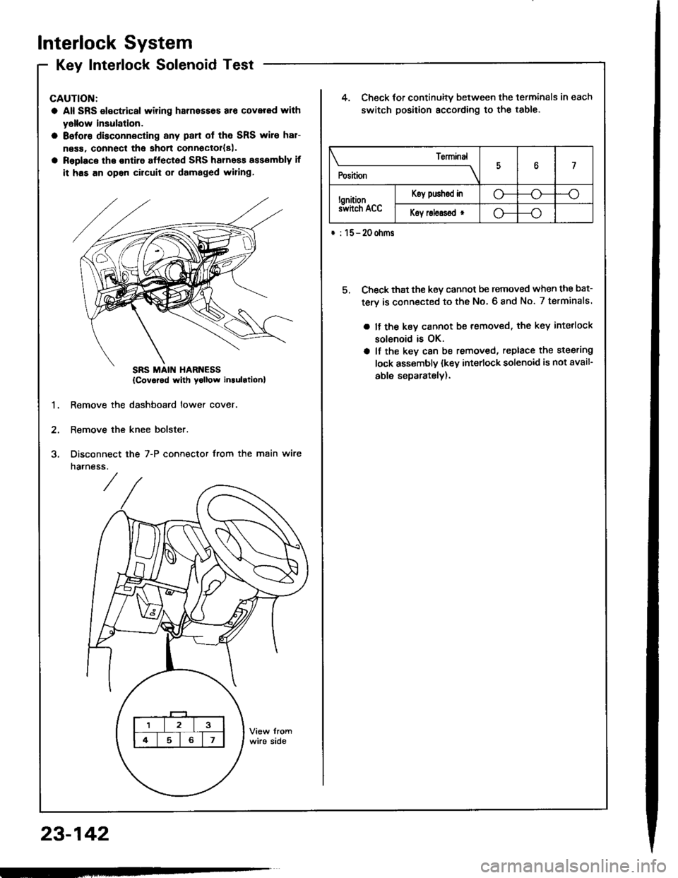
Interlock System
Kev Interlock SolenoidTestKey IntenocK Dorenoro I esr -
CAUTION:
a All SRS electrical wiring harnesses ar€ covered rYith
yollow insulation.
a 8eforc disconnecting any pan of the SRS wire har-
ness. connecl tha short connoclol{s|.
a Raplace the ontire affected SRS harness assembly if
it has an opon circuit or damaged wiring,
4. Check for continuitv between the terminals in each
switch position according to the table.
5, Check that the key cannot be removed when the bat-
tery is connected to the No. 6 8nd No. 7 terminals.
a It the kev cannot be removed, the key interlock
solenoid is OK.
a lf the key can be removed, replace the steering
lock assembly (key interlock solenoid is not avail-
able separately).
1.Remove the dashboard lower cover
Remove the knee bolster.
Disconnect
narness.
the 7-P connector from the main wire
\______________rry
Position7
lonitionS hch Acc
Koy push€d ino---o
Koy roleEsod r--o
* : l5-20ohms
{Covorod with yollow inlulrtionl
23-142
Page 1249 of 1413
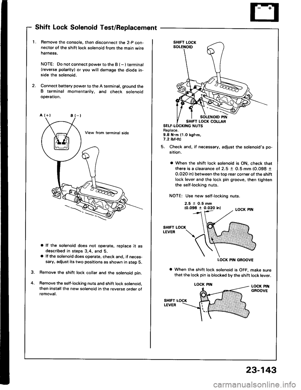
Shift Lock Solenoid Test/Replacement
Remove the console, then disconnect the 2-p con-neclor oJ the shift lock solenoid from the main wireharness.
NOTE: Do not connect powe. to the B { - ) terminat(reverse polarity) or you will damsge the diode in-side the solenoid.
Connect battery power to the A terminal, ground theB terminal momentarily. and check solenoidoDeralron.
a lf the solenoid does not operate, replace it asdescribed in steps 3,4, and 5.a lJ the solenoid does operate, check and, if neces-sary, adiust its two positions as shown in step 5.
Remove the shift lock collar and the solenoid pin.
Remove the selflocking nuts and shift lock solenoid,then installthe new solenoid in the reverse otder otremovat.
a
Replace.9,8 N.m {1.0 kgl.m,7.2 tbl.hl
5. Check and, if necessary, adjust the solenoid's po-
sition.
a When the shift lock solenoid is ON, check that
there is a clearance ol 2.5 1 O.5 mm {O.O98 I
O.O2O in) between the toD rear corner ot the shift
lock lever 8nd the lock pin groove, then tighten
the selflocking nuts.
NOTE: Use new self-locking nuts.
2.5 t O.5 mm{0.098 t 0.020 inl
SHIFTLEVEB
LOCK PIN GROOVE
a When the shift lock solenoid is OFF, make surethat the lock pin is blocked bv the shift lock lever.
LOCK PINGROOVE
LOCK
LOCK PIN
23-143
Page 1255 of 1413
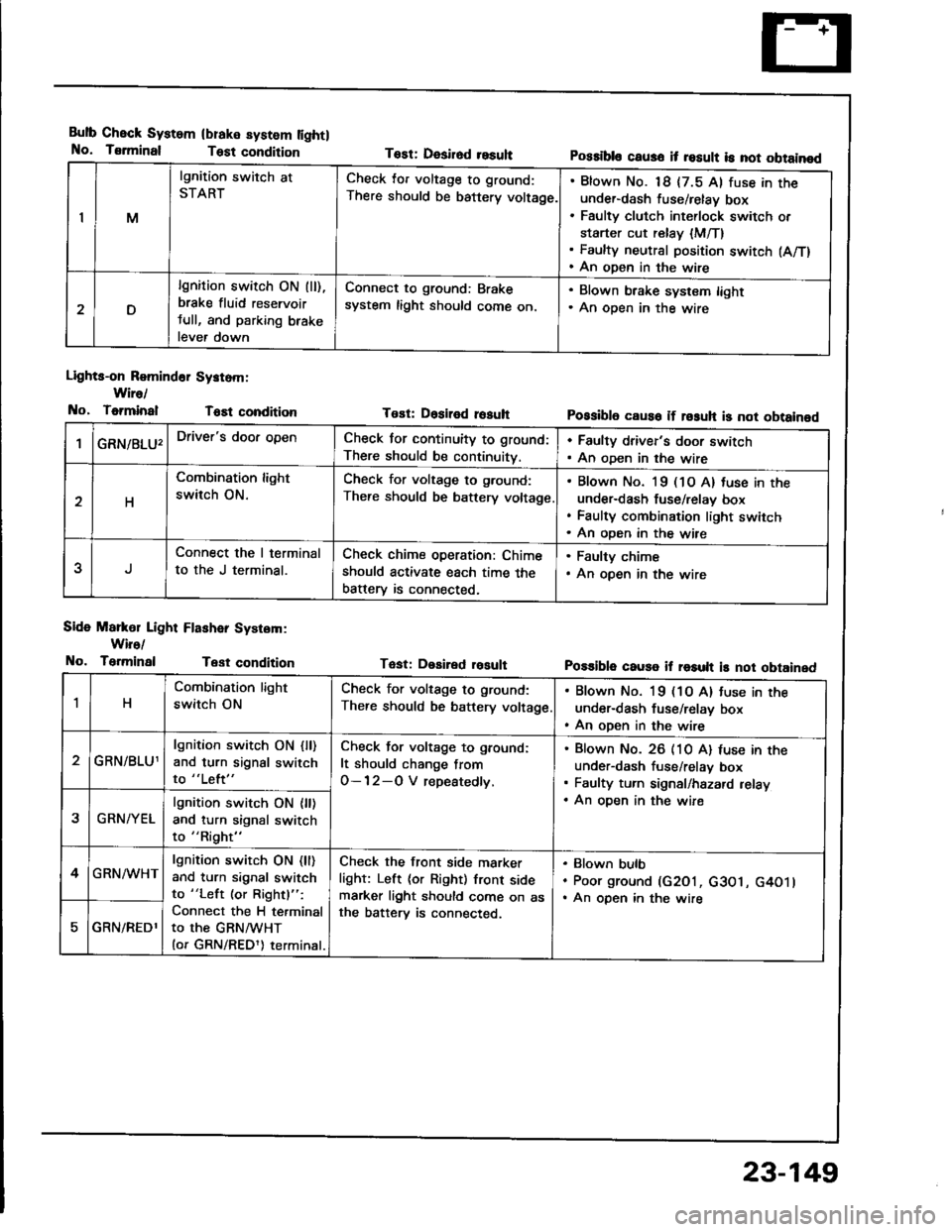
Bulb Check System
No. Tsrminal
(blake system lightl
Test condition
Lights-on Romind6r Systom:
Wire/
No, ToiminalT6Et condition
Side Markol Light Flashar System:
Wiro/
No. TerminalTest condition
Tost: Desirod resuhPossibls caus6 it result is not obtainod
Tost: Dositod rosuhPossibl6 caus6 if rosuh is not obtainod
Tast: Desired rosultPo$ible cause if result is not obtained
IM
lgnition switch at
STARTCheck lor voltage to ground:
There should be battery voltage.
Blown No. 18 {7.5 Al fuse in theunder-dash fuse/relay box
Faulty clutch int€rlock switch or
starter cut relay {M/T}Faulty neutral position switch (A/T)
An open in the wire
D
lgnition switch ON (ll),
brake fluid reservoir
tull, and parking brake
lever down
Connect to ground: Brake
system light should come on.
. Blown brake system light. An oDen in the wire
GRN/8LU'Driver's door openCheck for continuity to ground:
There should be continuity.
. Faulty driver's door switch. An oDen in the wire
H
Combination light
switch ON.
Check for voltage to g.ound:
There should be battery voltage
Blown No. l9 (1O A) tuse in the
under-dash fuse/relav box
Faulty combination light switch
An oDen in the wire
5
Connect the I terminal
to the J terminal.
Check chime operation: Chime
should activate each time the
batterv is connected,
. Faulty chime. An open in the wire
1H
Combination light
switch ON
Check for voltage to ground:
There should be battery voltage
. Blown No. 19 (1O A) tuse in the
under-dash fuse/relay box. An open in the wire
GRN/BLU1
lgnition switch ON {ll)and turn signal switch
to "Left"
Check for voltage to ground:
It should change from
O-12-O V repeatedly.
Blown No. 26 (10 A) luse in theunder-dash fuse/relav box
Faulty turn signal/hazard relay
An oDen in the wire2GRN/YEL
lgnition switch ON {ll)and turn signal switch
to "Right"
4GRN/WHTlgnition switch ON (ll)
and turn signal switch
to "Left (or Rightl":
Connect the H terminal
to the GRNMHT(or GRN/REDl) terminal.
Check the front side marker
light: Left (or Right) front sidemarker light should come on asthe batterv is connected.
Blown bulb
Poor ground (G2O1, c3O1, G4O1lAn open in the wire
GRN/REDl
23-149
Page 1270 of 1413
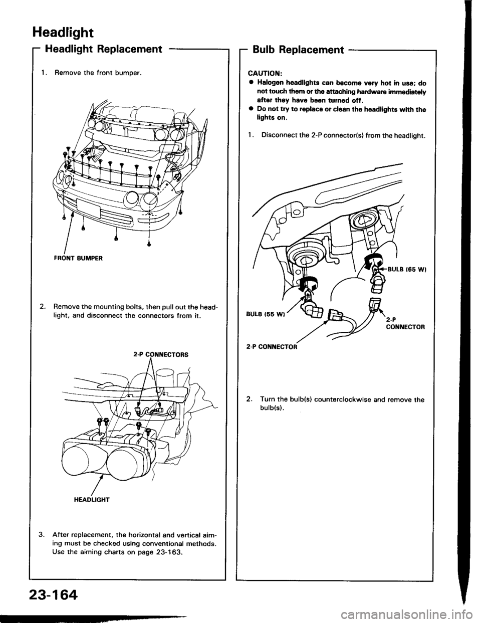
Headlight
Headlight Replacement
1. Remove the front bumoer.
Remove the mounting bolts, then pullout the head-
light, and disconnect the connectors from it.
Afte. replacement. the horizontal and vertical aim-ing must be checked using conventional methods,
Use the aiming charts on page 23-163.
Bulb Replacement
CAUTION:
a Halogon headlights can bocomo voly hot in usa; do
not touc$ them or tho attaching hardware imm6diatoly
arter they hava been lurnod off,a Do not try to roplace or cl6an the headlights with thelights on.
I . Oisconnect the 2-P connector(s) from the headlight.
coNlrtEcToR
2. Turn the bulb(s) counterclockwise and remove the
bulb(s).
FRONT BUMP€R
HEADLIGHT
23-164
Page 1271 of 1413
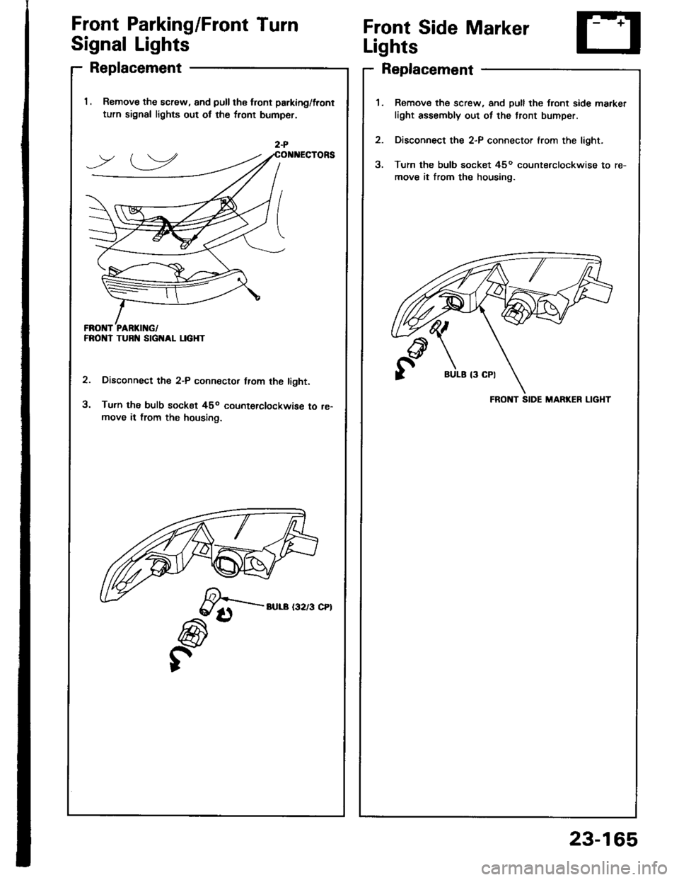
Front Parking/Front TurnFront Side Marker
LightsSignal Lights
Replacement
l. Remove the screw, and pull the front parking/front
turn signal lights out ot the tront bump6r.
Disconnect the 2-P conn€ctor trom the tight.
Turn the bulb sock€t 45o counterclockwise to re-move it from the housing.
Replacement
Remove the screw, and pull the front side marker
light assembly out of the tront bumper.
Disconnect the 2-P connector from the lioht.
Turn the bulb socket 45o counterclockwise to re-
move it from the housing.
BULE {3 CPI
FRONT SIDE MARKER LIGHT
23-165
Page 1275 of 1413
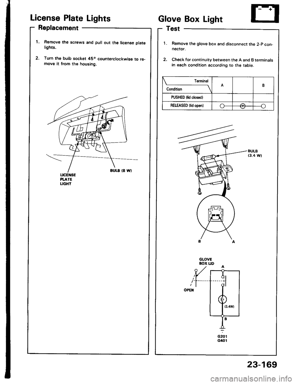
License Plate Lights
Replacement
Remov€ the screws and pull out th6 license platelights.
Turn the bulb socket 45o counterclockwise to re-move it from the housing.
ciorG4{t1
Glove Box Light
Test
Remove the glove box and disconnect the 2-p con-neclor.
Check for continuity between the A and B terminals
in each condition according to the table.
BULB(3.4 W)
Condition
T€rminalB
PUSHED {lid closodl
REI"EASED {lid oDen)o-/:\---o\7
ql-----11
dl
23-169
Page 1284 of 1413
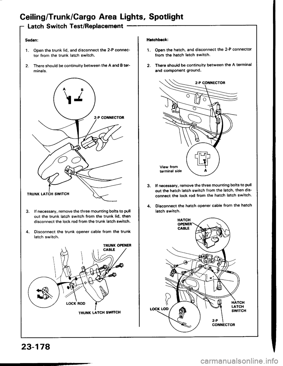
Ceiling/Trunk/Cargo Area Lights, Spotlight
Latch Switch Test/Replacemsnt
Sedan:
1. Open the trunk lid. and disconnect the 2-P connec-
tor from the trunk latch switch.
2. There should be continuity between the A and B ter-
minals.
ll necessary, remove the three mounting bolts to pull
out the trunk latch switch from the trunk lid, then
disconnect the lock rod from the trunk latch switch.
Disconnect the trunk opener cable from the trunk
latch switch.
4.
\j
CC
TRU'{K OPG ER
TRUNK LATCH SWITCH
lhtchb.ck:
1 . Op6n the hatch, and disconnect the 2-P connector
trom the hatch latch switch.
2. There should be continuity between thg A terminal
and component ground.
lf necessary, remove the three mounting bolts to pull
out the hatch latch switch trom the latch, then dis-
connact the lock rod Jrom the hatch latch switch
Disconnect the hatch opener cable trom the hatch
latch switch,
3.
4.
23-178
Page 1289 of 1413
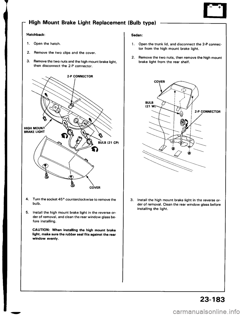
High Mount Brake Light Replacement {Bulb type)
Hatchback:
1. Open the hatch.
2. Remove the two clips and the cover.
3. Remove the two nuts and the high mount brake light,then disconnect the 2-P connector.
Turn the socket 45o counterclockwise to remove thebulb.
Install the high mount brake light in the reverse or-
der of removal, and clean the rear window glass be-
tore installing.
CAUTION: Whon installing ih6 high mount brakelight. make sur6 the rubber soal fits against the realwindow ev6nly.
4.
Sadan:
1. Open the trunk lid, and disconnect the 2-P connec-
tor trom the high mount brake light.
2. Remove the two nuts, then remove ths high mount
brake light from the rear shelt.
2-P CONt{ECTOR
Install the high mount brake light in the reverse or-
der of removal. Clean the rear window glass before
installing rhe light.
2
23-183
Page 1304 of 1413
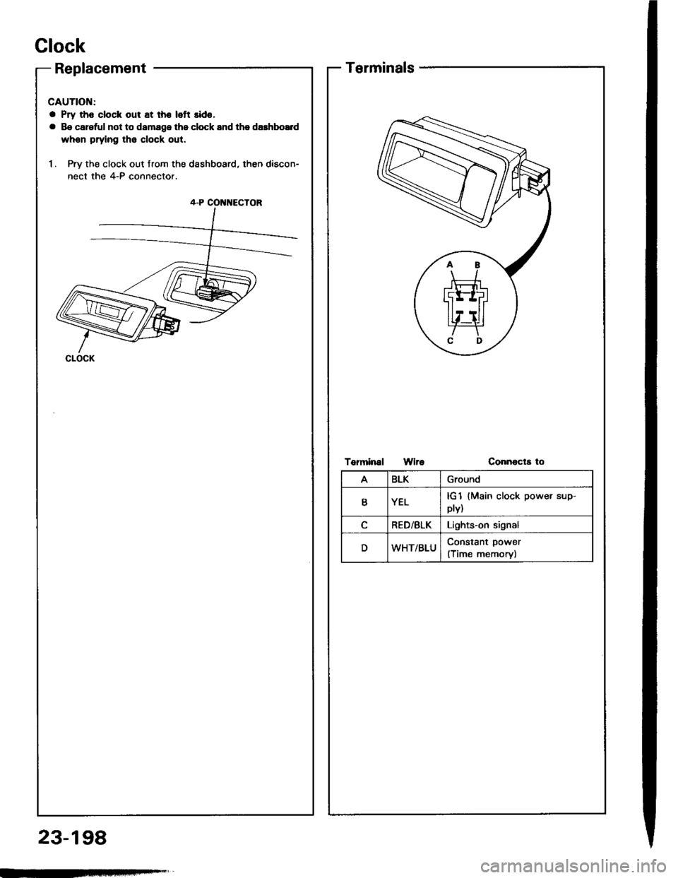
Clock
Replacement
CAUTION:
a Pry th6 clock out at th€ left sido,
a Be carsful not to damage the clock and the dashboE d
whon prying the clock out.
1. Pry the clock out from the dashboard, then discon-
nect the 4-P connector.
4-P COI{NECTOR
CLOCK
23-198
Terminals
Torminal WiroConnecta to
ABLKGround
YELplv){Main clock power sup-
RED/BLKLights-on signal
DWHT/BLUConstant power
(Time memory)