body HONDA INTEGRA 1994 4.G Owner's Manual
[x] Cancel search | Manufacturer: HONDA, Model Year: 1994, Model line: INTEGRA, Model: HONDA INTEGRA 1994 4.GPages: 1413, PDF Size: 37.94 MB
Page 236 of 1413
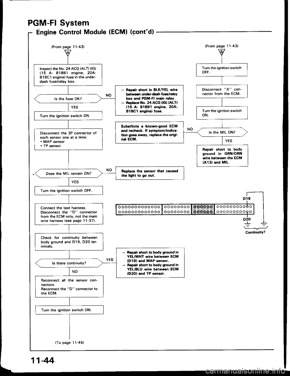
(From page 1 1-43)
Inspect the No. 24ACG {ALT) (lG)(15 A: 81881 engine, 2OA:818C1 enginel fuse in the under-dash fuse/relav box.
- R.pllr .hon in BLK|rEL wlr6batr.v€qr undariair luro/Fbybox lnd FGM-FI m.in .obv.- noebco lto. 24 ACG {lG) nLT)(15 A: 81881 ongin., 2OA:Bl8Cl onein.l tu!6.
ls the fuse OK?
Turn the ignition switch ON.
Disconnect the 3P connector oteach sensor one al a time:. MAP sensor. TP sensor
Rcplaoo thg lgnlor that caur6dth. llght to Oo out.Does the MIL remain ON?
Turn the ignition switch OFF.
connect the test harness.Disconnect the "D" connectorfrom th€ ECM only, not the mainwire harness (see page 11-37).
Check tor continuity betweenbody ground and D19, O2O ter-minals,
- Bapai? rhod ro body g.ound inYEL/WHT wi.e boiwoon ECM(Dl9) .nd MAP ..n3or.- R.p!k shon to body ground inYEL/BLU wire b.lwo6n ECM(O2Ol .nd TP 3on!or.
Reconnect all tho sensor con-necrors,Reconnect the "D" connector torhe ECM.
Turn the ignition switch ON.
{To page 11-45}
System
Control Module (ECMI (cont'dl
PGM-FI
Engine
Dt9I
I oooooooooo ooo I oooooooo I omoool o oooooooooo | |I ooooooooooooo I oooooooo 1o('oe(lo I ooooooooooo | |-lD2O I
\-.J
Continuity?
(From page 11-43)
Disconnect "A" con-nector from the ECM.
Subrtltute r knowngood ECM.nd rochock. ll lymptom/indics-tlon g@a rw!y, rephco tho origi-n.l ECM.
ls the MIL ON?
Ropair short to bodygiound in GRN/ORNwir6 botwoon tho ECMlA131 6nd MlL.
11-44
Page 237 of 1413
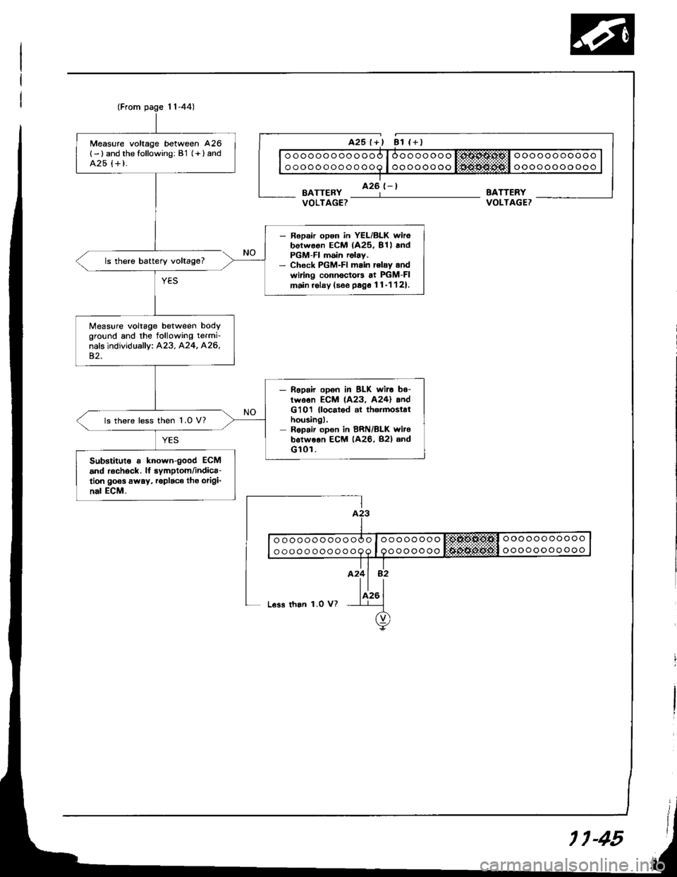
(From page 1l-44)
Measure voltage between 426
{- ) and the following: B'1 (+ } andA25 {+ t.
- Ropsir opon in YEL/BLK wirobotwoon ECM (425, 81l andPGM-FI m6in relay.- Chock PGM-FI main rclay andwiring connectors at PIGM-FImain.olay (soe psg6 11-1121.
ls there battery voltage?
Measure voltage between bodyground and the tollowing termi-nals individually: A23. A24, A26,42.
- noprir opon in BLK wit. b6-twson ECM 1A23, A24l andG'101 {locatod al th6.mostathousingl.Repair opon in BRN/BLK witebotweon ECM (A26, B2l andGl0r.
ls there less then 1.0 V?
Substitut6 r known{ood ECM
and r6chock. lf symptom/indica-tion goos away, roplaco tho origi-nal ECM.
BATTERYVOLTAGET
ooooooooooo
oooooooooooooooooooooo
ooooooooooo
oooooooo
ooooooo
L€ss than 1.0 V?
11-45
Page 240 of 1413
YES
PGM-FI
Heated
11-471
System
Oxygen Sensor Heater (cont'd)
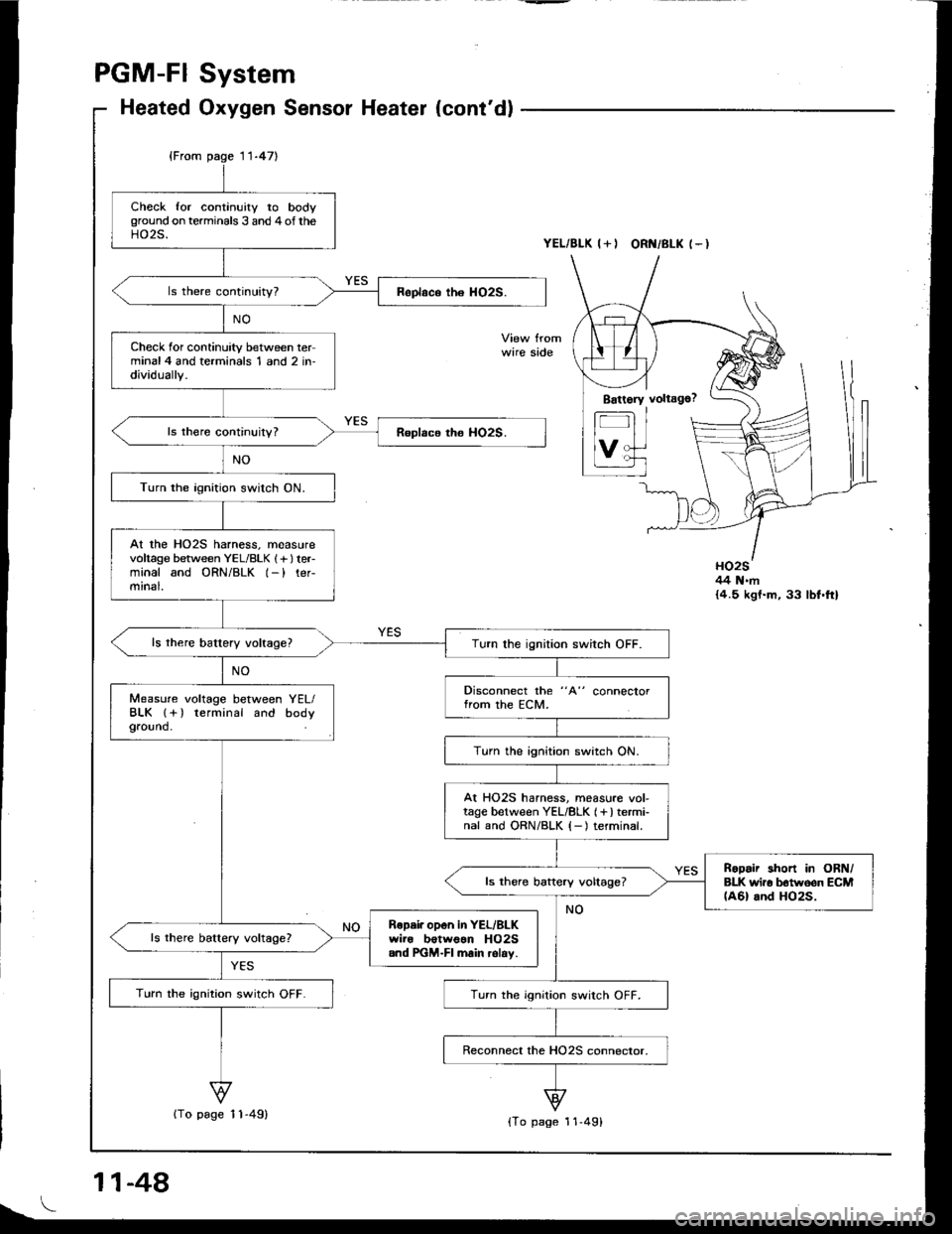
YEL/BLK I+I ORI{/BLK (-I
wire side
HO2S44 N.m{4.5 kgt.m, 33 lbf.ft}
Check for continuity to bodyground on terminals 3 and 4of theHO2S.
Check for continuity between terminal4 and terminals 1 and 2 in-dividually.
Turn the ignition switch ON.
At the HO2S harness. measurevoltage between YEL/BLK 1f lteFminal and ORN/BLK l-) ter-mrnal.
Turn the ignition switch OFF.
Disconnect the "A" connectorfrom the ECM.Measure voltage between YEL/BLK l+) terminal and bodyground.
Turn the ignition switch ON.
At HO25 harness, measure vol-tage between YEL/8LK (+) termi-nal and ORN/BLK {-) terminal.
RoDair short in ORN/BLK wir6 b6tw6on ECM(A6l and HO2S.ls there baftery voltage?
Ropai. opon in YEL/BLKwire botwoan HO2S.nd PGM-FI main relav.
Turn the ignition switch OFF.Turn the ignition switch OFF.
11-48
{To page 11-49){To page 11-49}
Page 248 of 1413
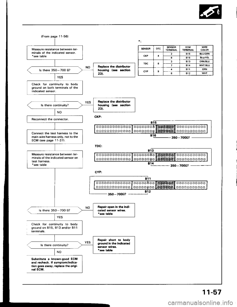
{From page 11-56)
Measure resistance between ter-minals of the indicated sensor.'see table
R.olac6 th. distributorhousing (8oo aoction231.ls there 35O-7O0 0?
Check for continuity to bodyground on both terminals ot theindicated sensor,
Rgplace tho di.tributorhousing llo€ loction23t.
Connect the test harness to themain wire harness only, notto theECM (see page 1 1-371.
Measure resistance between ter-minals of the indicated sensor ontest harness.'see table
Roprir opon in tho indi-cated senaoa wirea.*soo tablols there 350 70O 0?
Repair short to bodyground in tho indicrl.dt€naor wiroa.i s€e tabla
SEIiSOFDTCSENSORECMTENMINAICOLOR
2815ATU/GFN
6816BTUTVEI
TDCa813ORN/BTU
814
9B1tORN
as12
o o ooooo oo ooo o I oooooooo l6coocl o oo ooo ooooo
o oooo ooooo ooo I oooo oooo lo{nofioo't oooooooo ooo
812350-7000?
Check for continuity to bodyground on 815. 813 and/or B'l 1terminals.
ls there continuity?
NO
Substituto a known-good ECMand rechock. lf symptom/indica-tion goes away. roplaco tho origi-n.l ECM.
11-57
Page 250 of 1413
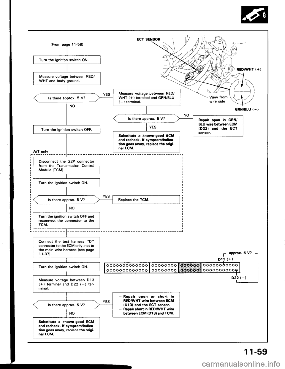
ECT SENSOR
GRN/BLU {-}
Turn the ignition switch ON.
Measure voltage betweon RED/WHT and body ground.
Measure voltage between RED/WHT {+}terminal and GRN/8LU(- ) terminal.ls there approx. 5 V?
ls there approx. 5 V?Ropai. opon in GRN/BLU wiro botwoon ECM(D221 and tho ECT36n3('r.Turn the ignition switch OFF.
Sub3tituto a known-good €CMand rochock. lf 3ymptom/indica-tion go6s away, roplaco the odgi-nal ECM.
Oisconnect the 22P connectortrom the Transmission ControlModule (TCM).
Turn the ignition switch ON.
ls there approx. 5 V7
Turn the ignition switch OFF andreconnect the connector to theTCM.
Connect the test harn€ss "D"
connector to the ECM only. not tothe main wire harness {see page11-37).
Turn the ignition switch ON.
Measure voltage between D13(+) terminal and D22 (-l ter-mlnal.
Repair opoa or shon inREO/WHT wiro botwoen ECMlDl3l and th6 ECT sonsor.R6pair shon in REO/WHT YYi..b6tw66n ECM {D131and TCM.
ls the.e approx. 5 V?
Substiluto a known-good ECMand rochock. ll lymptom/indica-tion goea 6wsy, replaco tho o.igi-n6l ECM,
A/T only
I
_i
11-59
Page 251 of 1413
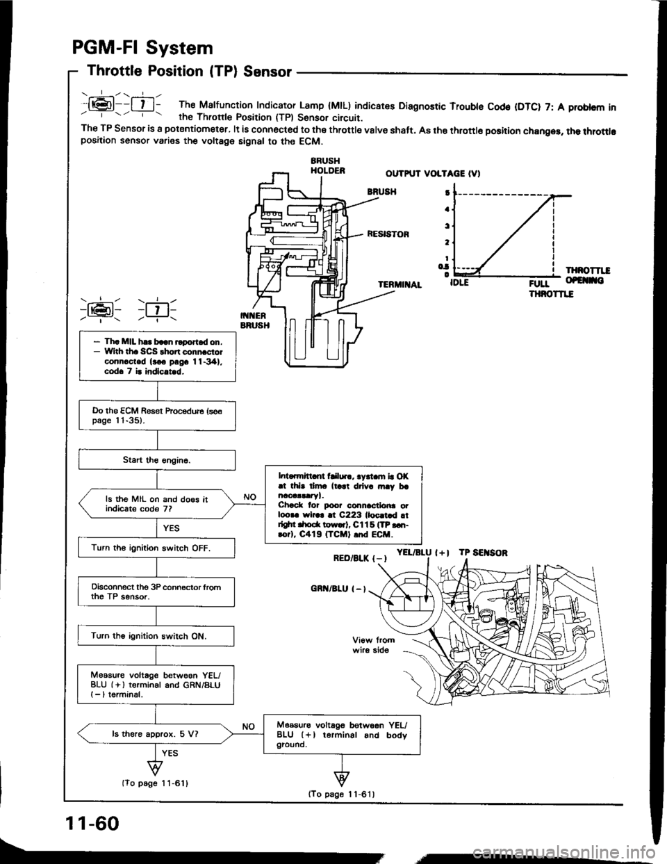
.:-\.-----ll@l--l t l- The Malfunction Indicator Lamp (MtL) indicatee Diagnostic Trouble Cod€ (DTC) 7: A problcm inrhe Thronle Position (TPl Sonsor circuit.The TP Sensor is a potsntiometer, lt is connected to the throttle valve shaft. A8 the throttlo position chan96, the throttlopositaon sensor varies the voltage signal to the ECM.
BBUSHHOLDER
PGM-FI System
Throttle Position (TPl Sensor
OUTPUT VOLTAGE IV)
BNUSH
RESISTOF
IXNOTTII
TERMIIIAL;0rr- of€ no
THNOTTIE
YEL/aLU l+l TP SEITSOR
I
a
t
t
Io.|o
RED/BLK {-I
cnn/BLu I - l
)ran1 )ril-Y- -?..
- Th. MIL h.. baln rlport d on.- With th. SCS thort conn.ciolconn.c-ted (rco pngc 11-341.codo 7 i. indlc.t d.
Do the ECM Reset hocedure (se€page l 'l-35).
l. ..mrtt nt fClur., lyrt m la OX.t thb dm. ll.at drlv. rn.y brncoaataryl.Chack lor poo? connactlo|ra otloora wlr.r !t C223 lloc.t d !tdgtn drod( tow..t, Cl15 ITP ...t-rorl, C419 (TCMI .nd ECM.
ls the MIL on and do€s itindicats codo 7?
Turn th€ ignition switch OFF.
Disconnect tho 3P connector lromth€ TP sensor.
Turn the ignition switch ON.
Meosu.o voltage betwoon YEL/BLU (i ) terminal and GRN/BLUI -, torminal.
Measurs voltagG betw66n YEUBLU (+l terminal and bodygiound.ls there approx. 5 V?
(To page 1 1-611
11-60
(To page 1 1-6'l )
,,,----
Page 254 of 1413
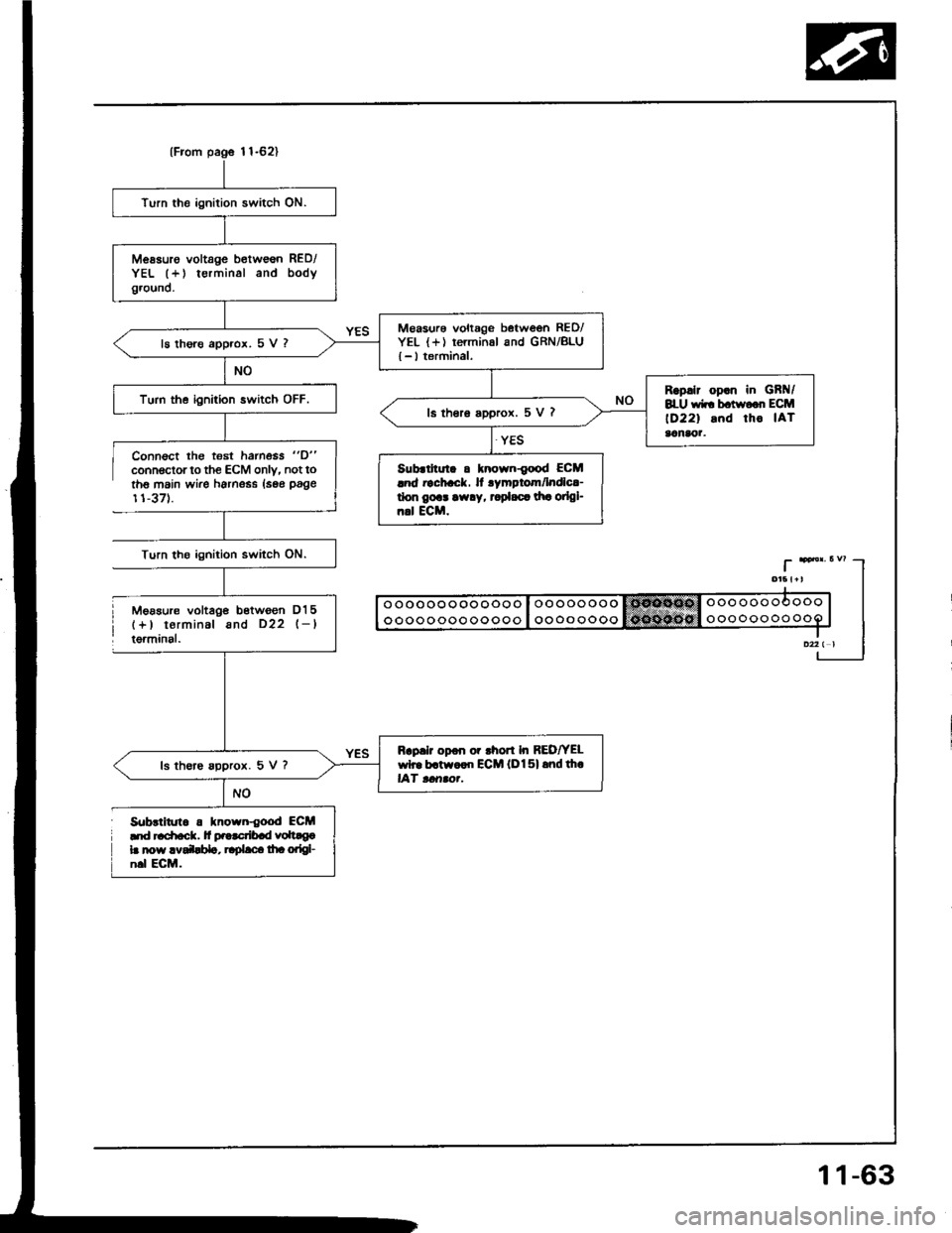
{From pag6 l1-62}
Turn the ignition switch ON.
Messuro voltage b€tw€6n RED/YEL (+) terminal and bodyground.
M€asurs voltage between RED/YEL {+) rerminal and GRN/BLU{ - I terminal,ls thore approx. 5 V ?
Rsp.lr op.n in GBt{/8LU wir bctwo.r ECM
lD22l snd tho IATaanaor.
Turn the ignition switch OFF.ls thero a99rox. 5 V ?
Sub.lhul. a tnown{ood ECMlnd rachack. It rymptom/lndlc!-don gort arv.y, t pl.c. dr! oilgl-n.l ECM.
Rap.lr opon or rhon In REDfYELwh. b.tw..n ECM lDl5l rnd th.lAf tcrrao.-ls th€re spprox. 5 V ?
Connsct lhg t€st hamess "D"
connoctor to the ECM only. not toth6 main wire harness lsse page
11-371.
Turn tho ignition switch ON.
Mgasur€ voltag€ bstwgon D15(+) terminal and D22 l-ltgrminal.
S0brlitrrt. . lnown{ood ECM'|d '.
Page 256 of 1413
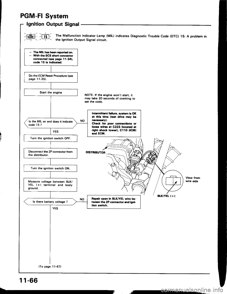
PGM-FI System
lgnition Output Signal
i16;11 :ffi1 The Malfunction Indicator Lamp (MlLl indic8tes Diagnostic Trouble Code (DTC) 15: A probl€m in'--=-- . -r- t the lgnition Output Signsl circuir.
I
NOTE| ll the onoine won't stan. itmay take 20 seconds ot cranking to5€t th€ COde.
D|STNIBUTOB
wir6 sido
- Th. MIL hsr b..n roport.d od.- Widr ths SCS .hon cohnecto.connoct€d {..o plgo 11-341,codg |5 i! indicatrd.
Do the ECM Reset ftocedure (seepage 'l'l-351.
Intarmltt nt hllur.. ryltam i. OK!t drlr dm. (t |l drlva mly bonaoaaalry).Chack tor Door cmnactiona orloo|. rYlrar !t C223 llocltld !trlghr .hoct tow.rl, Cl10 (lCMl.nd ECM.
ls th€ MIL on and do€s it indicatecode 15 ?
Turn the ignition swirch OFF.
Turn the ignition switch ON.
Measure voltage betwoon BLK/YEL (+) terminal snd bodygrouno.
R.p.ir op.n In BLK/YEL wlr. bo-ftvarn th. 2P conn.cior lnd ioni-tion rwitch.
ls the.e battory voltage ?
(To page 11-67)
11-66
re*,
Page 261 of 1413
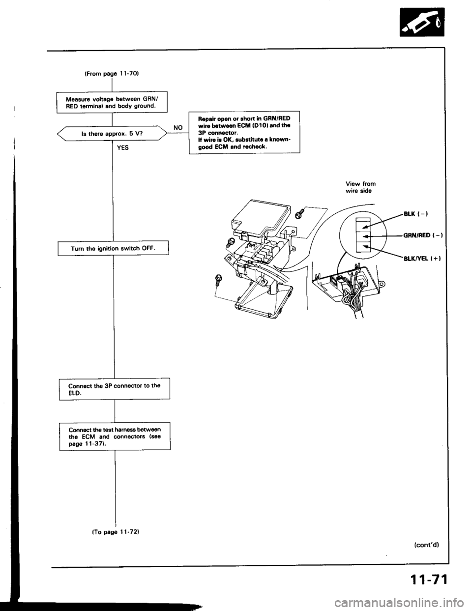
(From pog6 1 1-7Ol
Meaauro voltage betweon GBN/RED ierminal and body ground.
Boplir opon 01lhort in GR /REDwir. batworn ECM (DlOl and tho
3P connoctor.1l wir. i! OK, .ubrtituta. known-good ECM .nd rochock.
13 the.e approx, 5 V?
Turn tho ignition switch OFF.
connect tho loat hamasa botweontho ECM and connectors (soa
pag€ 11-37),
wire side
BLK {_I
GR /NED I-I
BLKIEL { + }
(To page 11-72)
11-71
Page 263 of 1413
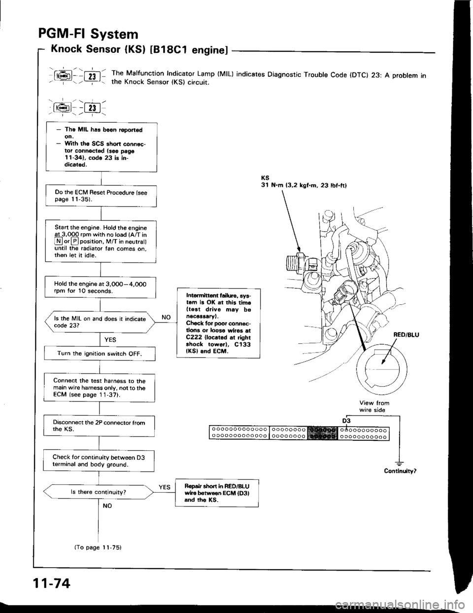
PGM-FI System
Knock Sensor (KS) tB18C1 enginel
ml- nl: The Malfunction Indicator Lamp (MlL) indicates Diagnostic Troubte Code (DTC) 23: A probtem inthe Knock Sensor (KS) circuit.
a6l--fzt.i--1/.---r+\
ware sido
o ooooo ooo ooo o looooooooo oooo ooo oo ooo I oooo oooo
11-74
- The MIL h6s boon r6port6don.- With th6 SCS ahort connec-tor connoctod (soe pago11-341, codo 23 is in-dicrtod.
Oo the ECM Reset Proceduro (seepage 11-35).
Start the engine. Hold the engineg!-3,Opq rpm with no load {A/T in
Lryl orlPlposirion, M/T in neurra until the radiator fan comes on,then let it idle.
Hold the engine at 3,0O0-4,000rpm for 10 seconds.Intomittor failure, ay5-t.m is OK at this tim6(teat drivo mav bonec€saary,.Chock tor Door connec-tion3 or loo3o wlaos etC222 {locatod 6r ghrshock tow6r), Cl33(KSl and ECM.Turn the ignition swirch OFF.
Connect the test harness to themain wire harness only, not to theECM (see page 1 1-37).
Check for continuity between D3terminal and body ground.
Ropdr short in RED/BLUwiro b€tweon ECM {D3land ths Ks.
(To page 11-75)