body HONDA INTEGRA 1994 4.G User Guide
[x] Cancel search | Manufacturer: HONDA, Model Year: 1994, Model line: INTEGRA, Model: HONDA INTEGRA 1994 4.GPages: 1413, PDF Size: 37.94 MB
Page 99 of 1413
wEc
6-38
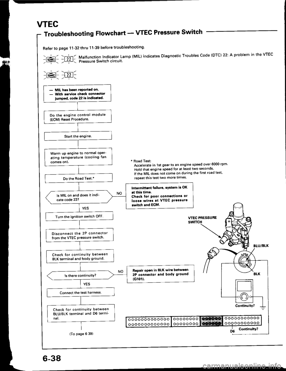
Troubleshooting Flowchart - VTEC Pressure Switch
Refer to page 11-32thru 11-39 beJore troubleshooting'
-.+- -r";-r- Malfunction Indicator Lamp (MlL) indicates Oiagnostic Troubles Code (DTC) 22: A problem in the VTEC- l{{?l- ;l ziz r: pressur€ Switch circuit.
-lr@l- |22 1-
* Road Test:Accolerato in lst gear to an engine speed over 6000 rpm
Hold that engine speed for at least two seconos'
lf the MIL does not come on during the first road test'
reoeat this test two more limes.
- MIL har bagn.oportcd on.- With t.rvic. chack connactor
iump.d, cod€ 22 it indic.t.d.
Do the engine control module(ECM)Reset Procedure.
Warm !p engine to normal oper-
ating temperstur€ (cooling fan
comes on).
Do the Boad T€st.'
Intc.mift.nt failu.o, ry3tom ia OK
at thi. tim..Chack for pool connaction3 ol
loo!. rvirat at VTEC Ptasturo3whch and ECM.
ls MIL on and does it indi'
cate code 22?
Turn lhe ignition switch OFF
Disconnect the 2P connector
lrom the VTEC Pressure switch.
Check Ior continuity between
BLK terminal and body ground.
Rcpair opcn in BLK wit. botwcon
2P connector rnd body ground
tG101l.
Check for continuity between
8LU/8LK terminal and D6 termi'
nal.
(To page 6 39)
Page 100 of 1413
(From page 6-38)
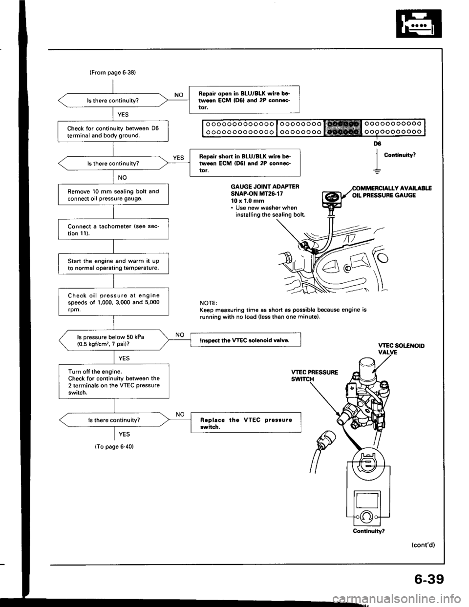
Ropair op€n in BLU/BLK $,iro between ECM lD6) and 2P conn.c-tor,
Check for continuity between D6terminal and body ground.
R6pri. short in BLU/BLK wir. bc-tweon ECM (D6l .nd 2P connec-toa,
Remove 10 mm sealing bolt andconnect orl pressure gauge.
Connect a tachometer {soe sec-tion 11).
Start the engine and warm it upto normal operatrng temperature.
Check oil pressure at enginespeeds of 1,000, 3,000 and 5,000rpm,
ls pressure bolow 50 kPa(0.5 kgflcm'�, 7 psi)?Inrpoct tho VTEC aolanoid v.lv..
Turn off the engine.Check lor continuity between the2 terminals on the VTEC pressure
switch.
o oooooo ooo ooo I oooooooo trt!*Hffi Oooooo ooooo
o oooo ooooo ooo I oo oooo ooo ooooo oo oo o
Coitlnuity?
D6
I
GAUGE JOINT ADAPTERSNAPON MT2&1710 x 1.0 mm. lJse new washer wheninstalling the sealing bolt.
Y AVAILAEIIOIL PRESSURE GAUGE
\-
]L
vtEc sot-€NotD
(cont'd)
NOTE:Keep mgasuring time as short as possible bocaus€ engine isrunning with no load (less than one minute).
YES
(To page 6-40)
Conlinuity?
6-39
Page 102 of 1413
WEC Solenoid Valve Inspection
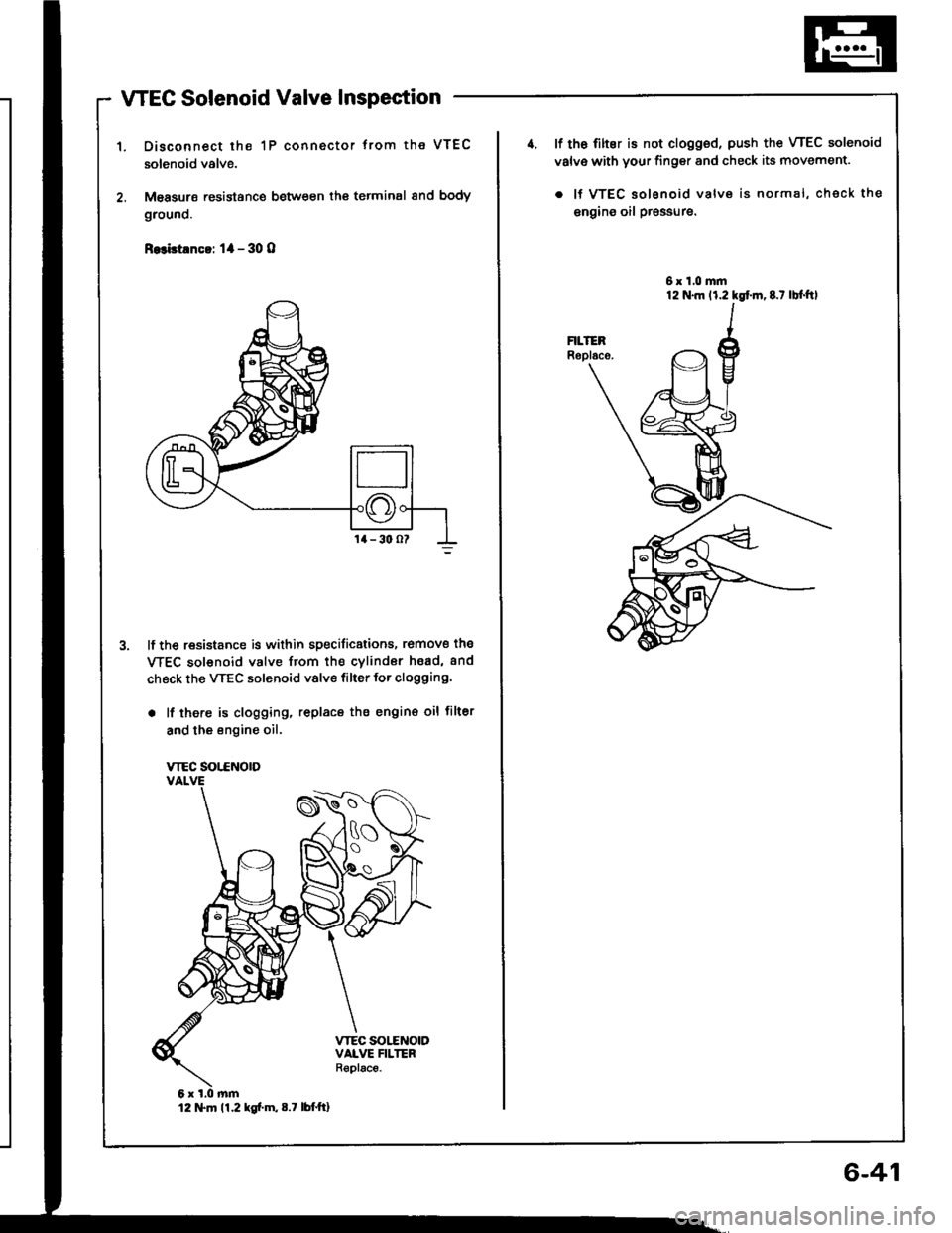
Disconnect the 1P connector trom the VTEC
solenoid valve.
M€asurs resistance between th€ terminal 8nd body
grouno.
R.3bt!nc!: 1l - 30 O
lf the resistance is within specificstions, romove the
WEC sol€noid valve from the cvlindor hsad, and
check the VTEC solenoid valve filter for clogging.
. lf there is clogging, replacs the engin€ oil filter
and the engine oil.
VTEC SOT.CNOTD
12 tTln 11.2 kg[.m,8.7 lbttt]
6-41
4. lf th6 filter is not clogged, push the VTEC solenoid
valv€ with your finger and check its movement.
. lf VTEC solsnoid valve is normal, check the
engins oil pr€ssure.
6x1.0mm
Page 180 of 1413
Intake Manifold
Replacement
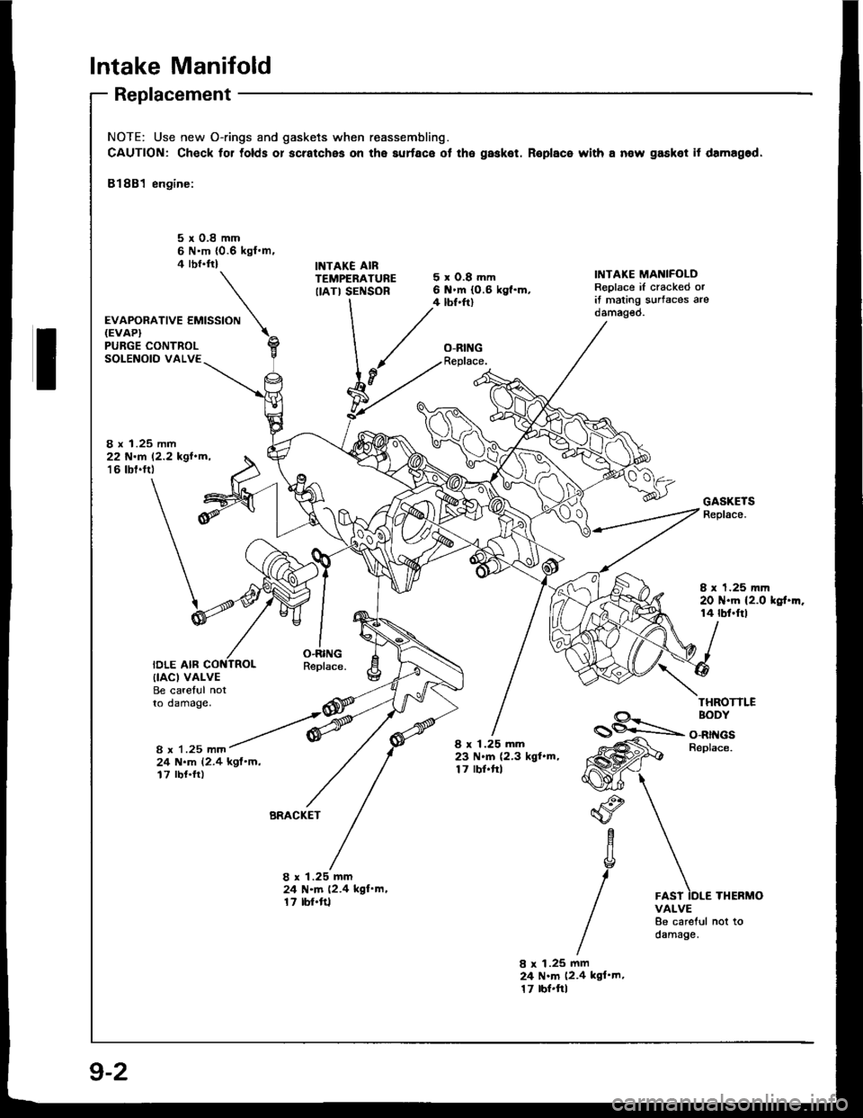
NOTE: Use new O-rings and gaskets when reassembling.
CAUTION: Check for tolds or scratches on the aurface ot the gasket. Roplace with a now gasket it damagod,
81881 engine:
5r0.8mm6 N'm {0.6 kgl.m.4 rbr.ftlINTAKE AIRTEMPERATUREIIATI SENSOR
'*o*ot'u""'""N
5xO.8mm6 .m (0.6 kg{.m.4 tbf.ftl
O-RINGReplace.
IiITAKE MANIFOLDReplace iI cracked orit mating s!rtaces arodamag€o.
PURGE CONTROLSOLENOID VALVE
8 x 1.25 mm22 N.r 12.2 kgl.m,'16 tbt.ftt
IDLE AIR
GASKETSReplace.
I x 1.25 mm20 N.m (2.0 kgt.m.14 rbf.ftl
O.RINGReplace.{IACI VALVEBe careful notto damage.THROTTLE
8 x 1.25 mm
BODY
O-RINGSBeplace.
24 N.m (2.4 kgf'm,17 rbf.ft)
8 x 1.25 mm23 N.m (2.3 kgl.m,17 lbf.frl
BRACKET"o
aYc
g
/
1.25 mmN.m (2.4 kgl'm,rbf'ft1
8x2417
8 x 1.25 mm24 N.m (2.4 kgl'm.17 tbr.ftlTHERMOVALVE8e careful not todamage.
9-2
Page 181 of 1413
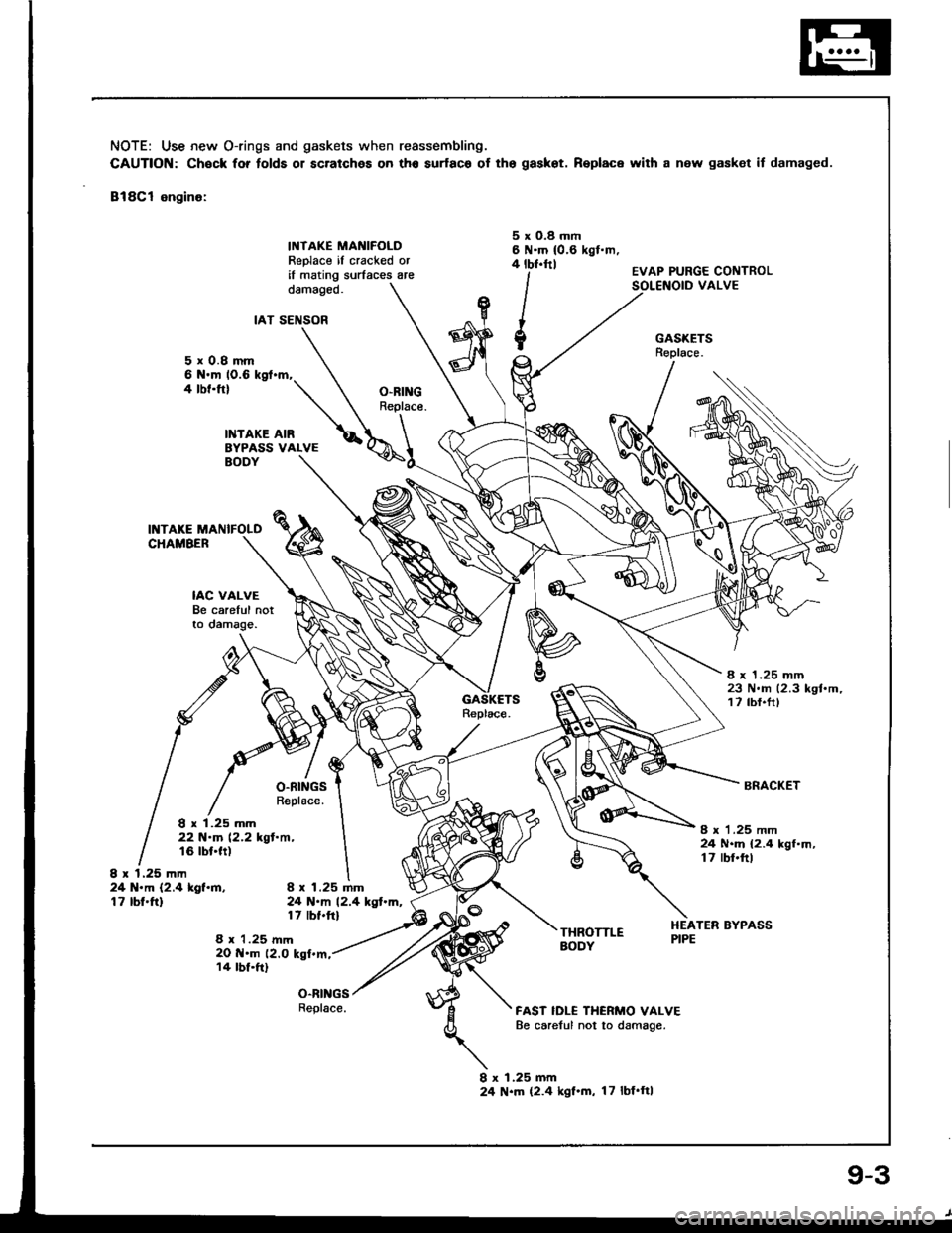
NOTE: Use new O-rings and gaskets when reassembling.
CAUTION: Chock for folds 01 scratches on th6 surfac6 of tho gaskot. Replace wilh a new gasket if damaged.
818C1 engino:
INTAKE MANIFOLDReplace il cracked oril mating surfaces are
5 x O.8 rnm6 N.m 10.6 kgl.m,4 tbt.ttl
lI
{,/
?,/
EVAP PURGE CONTROLVALVEdamageo.
IAT SENSOR
5xO.8mm6 N.m 10.6 kgf.m,4 tbf.ftl
INTAKE AIRBYPASS VALVE
IAC VALVEBe carelul notlo oamage.
O.RINGSReplace.
GASKETSReplace.
O.BI GReplace.
BODY
INTAKE MANIFOLDCHAMBER
8 x 1.25 mm23 N.rn 12.3 kgt'm,17 tbf.frl
I x 1.25 mm22 N.m 12.2 kgl.ft,t6 tbt.tt)
BRACKET
8 r 1.25 mm24 N.m {2.4 kgf.h,t7 rbr.ftl
8 x t.25 mfi24 N.m (2.4 lgf.m.17 tbt.ft)I r 1.25 lnm24 N.m 12.4 kgt.m,17 tbt.ftl
8 x 1.25 mm20 .m (2.0 kgt.m,14 tbf.ftl
THROTTLEAODY
FAST IDL€ THERMO VALVEBe carelul not to damage.
HEATER BYPASSPIPE
o-Rt GsReplace.
I x 1.25 mm24 N.m (2.4 kgl.m, 17lbf'ft|
9-3
Page 186 of 1413
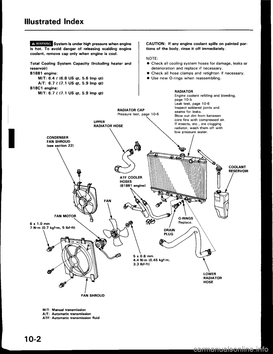
lllustrated Index
@ sy"t". is under high plessure when engine
is hot. To avoid dsnger of relsssing scalding engine
coolant. remove cap only when engine is cool.
Total Cooling System Capacity (lncluding heater and
r€servoirl
Bl8Bl engine:
Mfl: 6.4 | {6.8 US qt, 5.6 lmp qt}
AlTt 6.7 | {7.1 US qt, 5.9 lmp qt}
Bl8Cl engine:
Mfi: 6.7 t {7.1 US qt, 5.9 lmp qt}
CAUTION: lf any engine coolant spills on paint€d por-
tions ot the body, rinse it ofl immediately.
NOTE:
a Check all cooling system hoses for damage. leaks or
deterioration and replace if necessary.
a Check all hose clamps and retighten if necessary.
a Use new O-rings when reassembling.
CONDENSERFAN SHROUD{soe soction 221
6 x 1.O mm7 N.m (O.7 kgt.m. 5 lbf.ftl
ATF COOLERHOSES{81881 6ngine)
RADIATOREngine coolant refilling and bleeding,page 10-5Leak test, page 'l0-6
Inspect soldered joints andseams for leaks.Elow out dirt from betweencore fins with compressed air.lf insects, etc., are clogging.adiator, wash them off withlow pressure water,
S!
P
R
U
COOLANTRESERVOIR
5x0.8mm4.4 N.m (O.45 kgf.m,3.3 lbl.fr)
M/T: Manual t.anamiaaionA/T: Automatic t.ansmiasionATF: Automatic t.ansmission fluid
\*
*)
FAN SHROUD
10-2
Page 194 of 1413
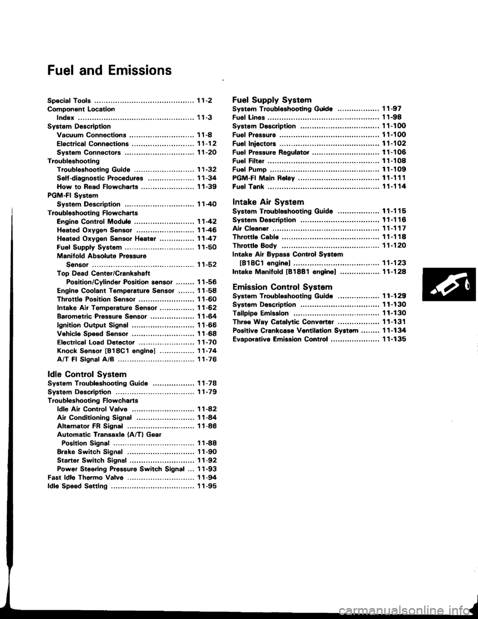
Fuel and Emissions
Spocial Tools ................ 1 1-2
Compon€nt Location
lndex ................. ...... 11-3
System Description
Vacuum Connectiona .......,.................... 1 1 -8
Efectrical Connections ....,.,.,......,...,,.....,'11-12
Syst€m Connectors ...,...,.................-.--. 11-2O
T.oubloshooting
Troubleshooting Guido .......................... 1 1-32
Self -diagnostic Procedures .,..,............... 1 1 -34
How to Road Flowcharts ...................,... 11-39
PGM-Fl System
Systom Description .............................. 1 l-4O
Troubleshooting Flowcharts
Engine Control Moduls ............... ........... 1 1 -42
Heated Oxygon Sensor ......,.................. 1 1-46
Heated Oxyg€n Sonsol Heatel .....,......... 1 1 -47
Fuel Supply System ..............-............... 1 1-50
Manitold Absolute Pressure
Ssnsor ............................................ 1 1-52
Top D6ad Cente./Crankshatr
Position/Cylindor Position sonsor ........ 1 1 -56
Engine Coolant Tempsrature Sonsor ....... 11-58
Throttlo Position Sonsor ........,..,,........... 1 1-60
Intake Air Temperaturs Sensor ............... 11-62
Baromet c Prsssuro Sensor ......,...,...,..,. 11-64
lgnition Output Signal ........................... 1 1 -66
Vehicle Spe€d Sensor ........................... 1 1 -68
Electdcal Load Dotector ....,...,..........,.... 1 1 -7O
Knock Sensor [818C1 engine] ............... 11-74
A/T Fl Signal A/B ................................. 1 1-76
ldle Contlol System
System Troubleshooting Guide .................. 1 1 -78
Systom Description ........ 11-79
Troubloshooting Flowchans
ldl€ Ail Control Valve ........................... 1 1 -82
Ail Conditioning Signal ......................... 1 1 -84
Altemator FR Signal ............................. 1 1 -86
Automatic Transaxle (A/T) Gear
Position Signal ......... 11-88
Brake Switch Signal ............................. 1 1 -9O
Startel Switch Signal ............................ 11-92
Power Steering Pressure Switch Signal ... 11-93
Fast ldle Thermo Valve ...................,......... 1 1 -94
ldls Speed S€tting .................................... 1 1 -95
Fuel Supply System
Systam Tloubloshooting Guid. .................. 1 1 -97
Fuol Linos ...................... 1'l -98
System Description ........ 11-100
Fuol Prassure ................. 11-100
Fu6l Ini6ctors ................. 11-102
Fuel Pressure Ragulato. .,. 11-106
Fuel Filter ...................... 11-108
Fual Pump ..................... 11-109
PGM-Fl Main F6lay ................................... 1 1"1 1 1
Fuel Tank ...................... t 1-114
Intake Air System
System Troubloshooting Guido .................. 1 1 -1 1 5
Systom Dascription ........ 11-116
Air Clean€r .................... 11-117
Throttls Cable ................'11-118
Throttl8 Body ................ 11-120
lntake Air Bypass Cont.ol Systsm
[B18Cl enginal .,......... 11-123
Intake Manilold [B1881 onginol ................. 11-128
Emission Control System
Systsm Troubleshooting Guido .................. 1 1 -1 29
Systam Doscription ........ 11-130
Tailpips Emission ........... 11-130
Thrae Way Catalytic Convortor ...,...,........., 11-131
Positiva CrankcaEo V6ntilation Systcm .,....., 11-134
Evaporativo Emission Contro|,..,..,.,.,,.,,..,.., 1 1-135
Page 198 of 1413
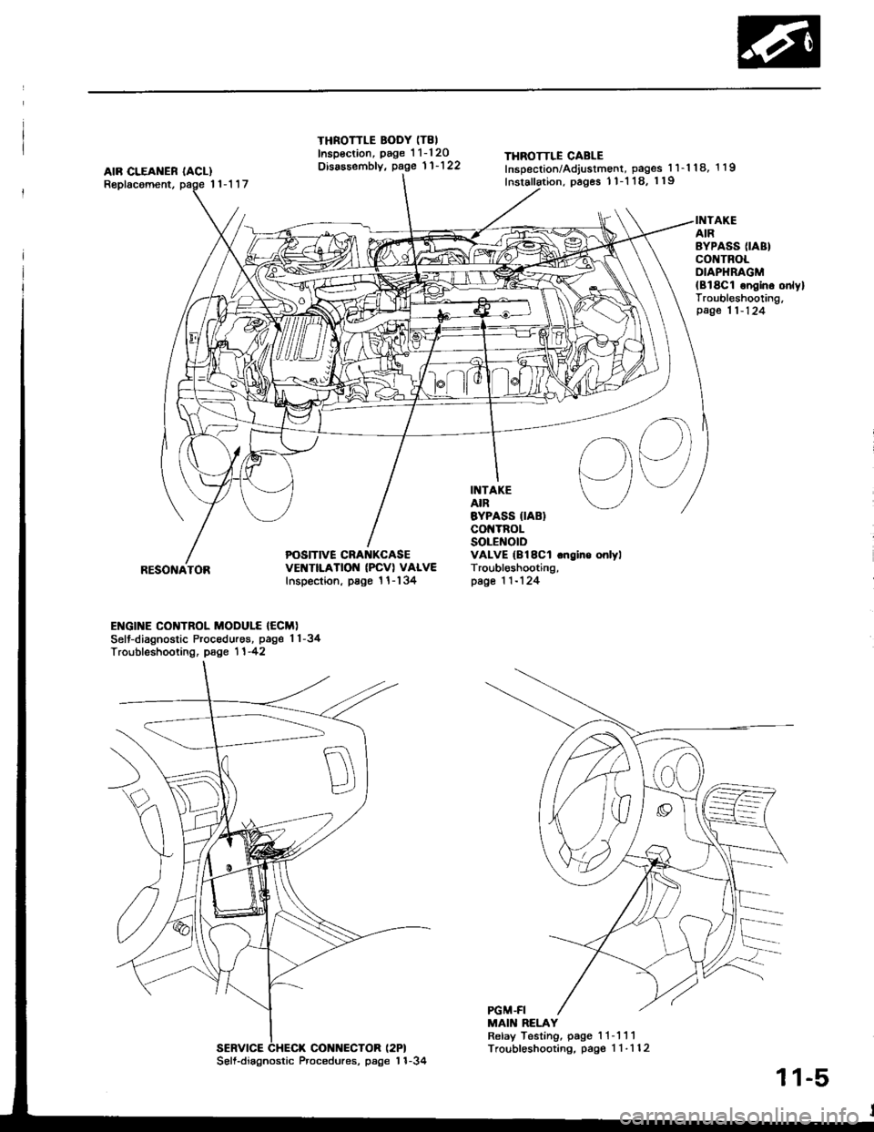
AIR CLEAI{ER IACL)Replacoment,11-117
THROTTLE BODY (T8I
Inspsction, page 1 1-120Disassembfy, page 11'122THROTTLE CABLEInsDection/Adjustment, pages 1 l-'l 18, 1 19
Inslallation, pages 1 1-1 18, 119
POSITIVE CRA KCASEvEt{TtLATtOt{ (PcVl VALVEInspection, psgo 1 l-134
INTAKEAIREYPASS IIABIco TnoLSOLENOIDVALVE (B18Cl .ngino onlylTroubl6shooting,page 1 1-124
INTAKEAIRBYPASS (IABI
co TROLOIAPHRAGM{Bl8C1 ongino onlylTroubleshooting,page 11-124
I
RESONATOR
ENGI]TE CONTROL MODULE {ECM)Selt-diagnostic Procedures, page 1 1-34Troubfeshooting, page 1 1 -42
MAIN RELAYRelay Testing, page 1 1- 111Troubleshooting, pag€ 1 1-112SERVICE CHECX CONNECTOR (2PI
56ll.diagnostic Procedures, page'l 1-34
11-5
Page 234 of 1413
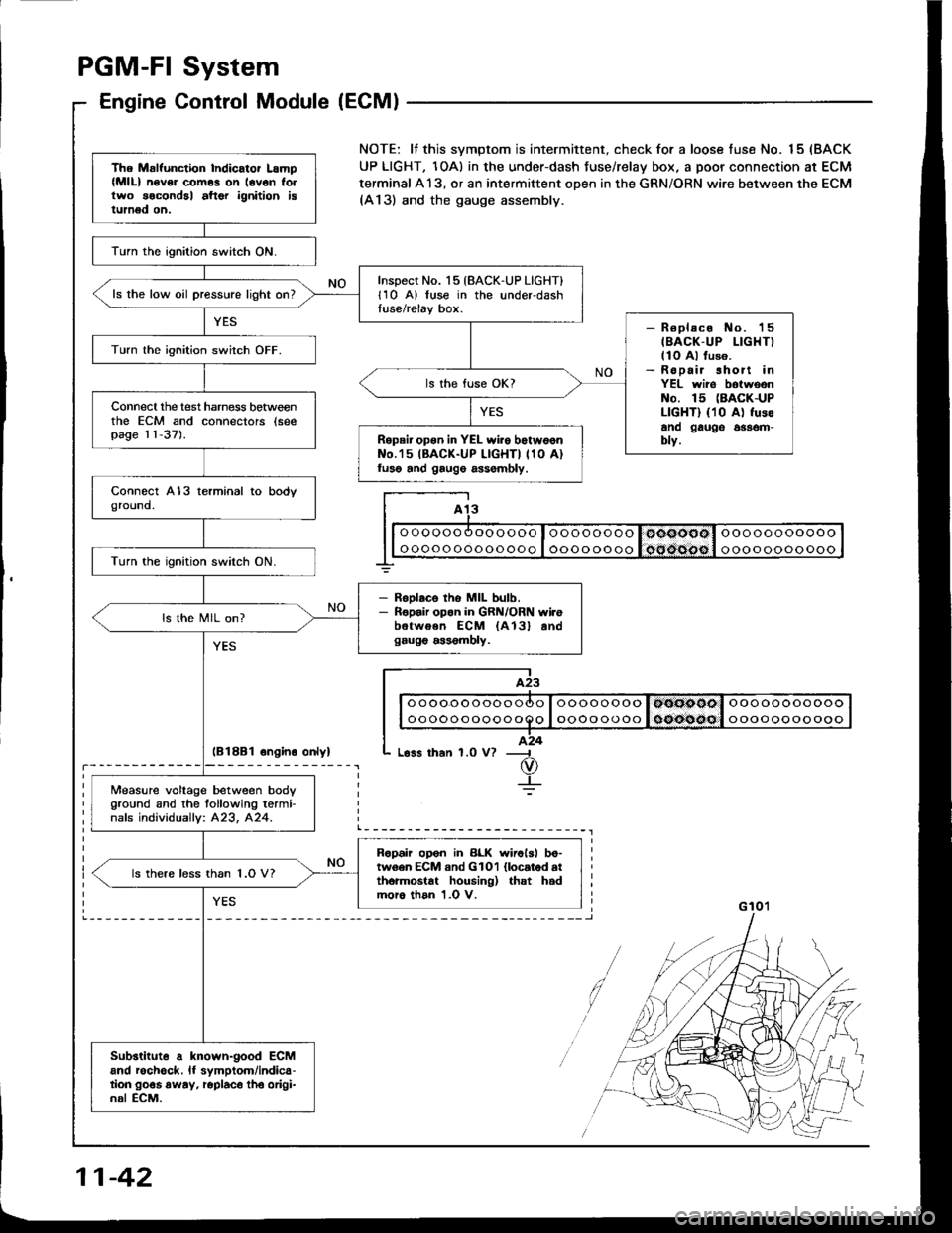
PGM-FI System
Engine Control Module (ECM)
lB18B1 ongino onlyl
The Malfunction Indicator Lamp(MlL) n6v6. com6s on lovon follwo socondal aftor ignition istumed on.
lurn the ignition switch ON.
Inspect No. 15 {BACK-UP LIGHT}l1O A) luse in the underdashtuse/relay box.ls the low oil pressure light on?
- R€placo No. 'l5
IBACK-UP LIGHT)llo Al fuso.- Ropair short inYEL wiro botwoonNo. 15 (BACK-UP
LIGHT) {10 A) fusoano gauge 6$om-blv.
Turn lhe ignition switch OFF.
ls the fuse OK?
Connecl the test harness betweenthe ECM and connectors (seepag€ 11-37).Repair opon in YEL wiio botw6onNo.'15 IBACK-UP LIGHTI 110 A)luso and gaug6 assombly.
Turn the ignition switch ON.
- RsDlaco tho MIL bulb.- Ropair opon in GRN/ORN wi.ebetwoen ECM {A13} andgaug€ a$6mbly.
ls the MIL on?
Measure voltage between body
Oround and the tollowing termi-nafs individuallv: 423, 424.
Ropah op6n in BLK wirolsl bo-tw6en ECM and GlOl llocatod atthormostat housing) that hadmoro than 1.0 V.
ls there less than 1.O V?
Substituto a known-good ECMand rochgck, lf symptom/indica-tion go€s away, roplaco tho origi-nal ECM.
NOTE: lf this svmptom is intermittent. check for a loose fuse No. 15 (BACK
UP LIGHT, 1OA) in the under-dash Juse/relay box, a poor connection at ECM
terminal A13, or an intermittent open in the GRN/ORN wire between the ECM(A13) and the gauge assembly.
I A13
I| | o oooo oooooooo I oooo oooo I ooooool ooooooooooo I
G 10'�l
11-42
Page 235 of 1413
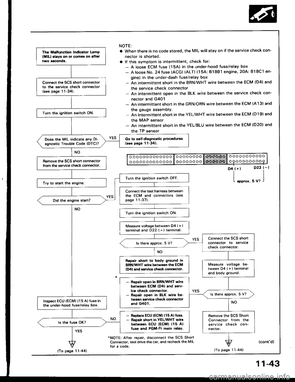
Th. ll.lfunction Indicltor Lamp
lMlll at!y3 on o. cornaa on alt6ltwo aacond!.
Connect the SCS short connectorto th6 sorvice check connector(see page 11-34).
Turn the ignition switch ON.
Go to iolfdiagnostic Proceduros(se€ pago 11-34).Does the MIL indicate anv Oi-agnostic Trouble Code (DTC)?
Romove th€ SCS shon connectorlrom the service ch€ck connector.
Turn the ignition switch OFF.
Try to start the engine.
Connect the test harness betweenthe ECM and connectors (see
page 11-37).
Turn the ignition switch ON.
Measure voltage botween D4 (+ )terminal and D22 { - ) terminal.
connect the SCS shonconnector to servlcecheck connector.ls there approx. 5 V?
Ropair shon to body g.ound inBRN/WHT wire betwoon th6 ECMlD4) end sorvlco chock connocto?.Measure voltage be_tween D4 {+} terminaland body ground.
- R6pair open in BRN/WHT witobotwoon EcM lD4) and s6rv-ice chock connactor.- Repoir opon in BLK wiro bo-twoon 36rvi@ chock connectoaand G4Ol.
ls there approx. 5 V?
InsDoct ECU {ECM) 115 A) tuse inth6 undeFhood luse/relav box.
- Rsolaco ECU {ECM} (15 Allus€.- R6pair shon in YEL/WHT wilobotw6on ECU lEcMl 115 A)fuso and PGM-FI main rolay.
Remove the scs shortConnector from theservice check con-nector.
ls the luss OK?
NOTE:
a When there is no code stored, the MIL willstay on if the service check con-
nector is shorted.
a tf this svmotom is intermittent, check for:
- A loose ECM fuse (15A) in the under-hood tuse/relay box
- A loose No. 24 fuse (ACG) (ALT) ( 1 5A: B1 8B 1 engine, 2OA: B18C 1 en-
gine) in the under-dash fuse/relay box- An intermittent short in the BRN/WHT wire between the ECM (D4) and
the service check connector- An intermittent oDen in the BLK wire between the service check con-
nector and G4O1- An intermittent shon in the GRN/ORN wire between the ECM (A 13) and
the gauge assembly.- An intermittent short in the YELMHT wire between the ECM (D19) and
the MAP sensor- An intermittent short in the YEL/BLU wire between the ECM (D20) and
the TP sensor
o ooooo ooo ooo o loooooooo liii:$A$.Ps,l o oo ooo ooooo
o oooo ooo o o ooo I oooooooooooooooooo
D4 (+)
l"oo,o'.
D22 t-l
uu,l
'NOTE: After repair, disconnect the SCS ShortConnsctor, test drive the car, and recheckthe MIL
lor a code.
(cont'd)
(To page 1 'l -44)lTo page 1 1-44)
11-43