body HONDA INTEGRA 1994 4.G Service Manual
[x] Cancel search | Manufacturer: HONDA, Model Year: 1994, Model line: INTEGRA, Model: HONDA INTEGRA 1994 4.GPages: 1413, PDF Size: 37.94 MB
Page 310 of 1413
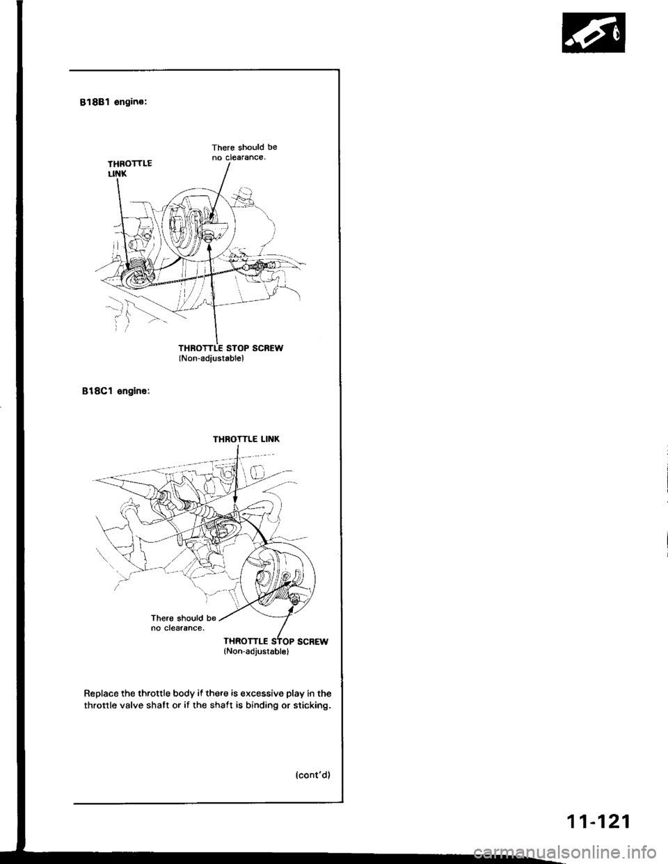
818B1 engino:
There should beno clearance.
THROTTLE STOP SCREW(Non-adiustablel
818Cl engine:
Replace the throttle body if there is excessive play in the
throttle valve shalt or if the shaft is binding or sticking.
THROTTLE LINK
(Non-adjusrablel
11-121
Page 311 of 1413
Intake Air System
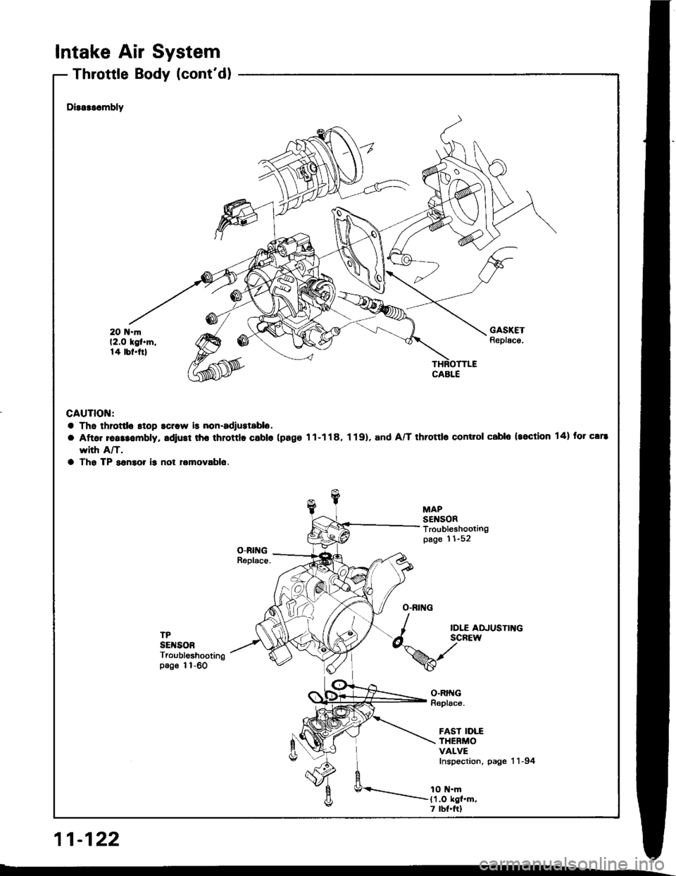
Throttle Body (cont'dl
11-122
Dirarssmbly
GAUTION:
a Ths throttlo stop scrow is non-adrustablo.
a Aftar reassombly, adiust rhr throttlo Gablo (pago 11-118, 1 19). and A/T throttlo contlol cabl6 (section 14) for c!r8
rYith A/T.
a Tho TP sonaor ir not lomovablo
MAPSENSORTroubleshootingpage 11-52
TPSETSORTroubleshootingpoge 1l-60
O.BING
I
d^'%
IDLE ADJUSTINGSCREW
o-RtftGReplace.
FAST IDLETHERMOVALVEInspection, page 11-94
1O N.m11.O kgl.m.7 tbf.ftl
Page 313 of 1413
Intake
Intake
Air
Air
System
Bypass (lAB) ControlSystem tBl8C1 enginel (cont'dl
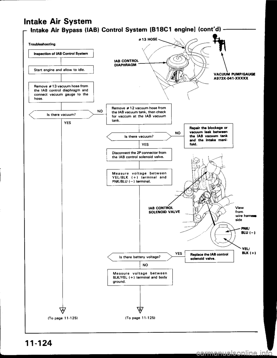
Troublcahooting
VACUUII PUMP/GAUG€A973X-041-XXXXX
fromwiro haanasid€
PI{K/BLU I-I
YEI/aLK l+l
tA8 COI{TROLDIAPHRAGM
Insp€ction of IAB Conltol Sytt.m
Start engino and allow to idle.
R€move # 13 vacuum hose tromthe IAB control diaph.agm andconnect vacuum gauge to thehose.
R€move # 12 vacuum hose fromth€ IAB vacuum tank, then checktor vaccum at the IAB vacuumtank.
Rcplir lh. block.g. otvacuufi laak boiwaaotha IAB vacuum tanklnd th. intlk m!ni-fold.
Disconnect the 2P conn€ctor lromthe IAB control solenoid valve.
Measure voltage betweenYEL/BLK (+l torminal andPNK/8LU l-) terminsl.
ls thoro battery voltage?
Measure voltage b€twee nBLK^|/EL (+) torminal and bodyground.
IAB CONTBOLSOLENOID VALVE
Page 315 of 1413
a
Intake Air System
Intake Air Bypass (lABl Control Valve IB18C1 enginel
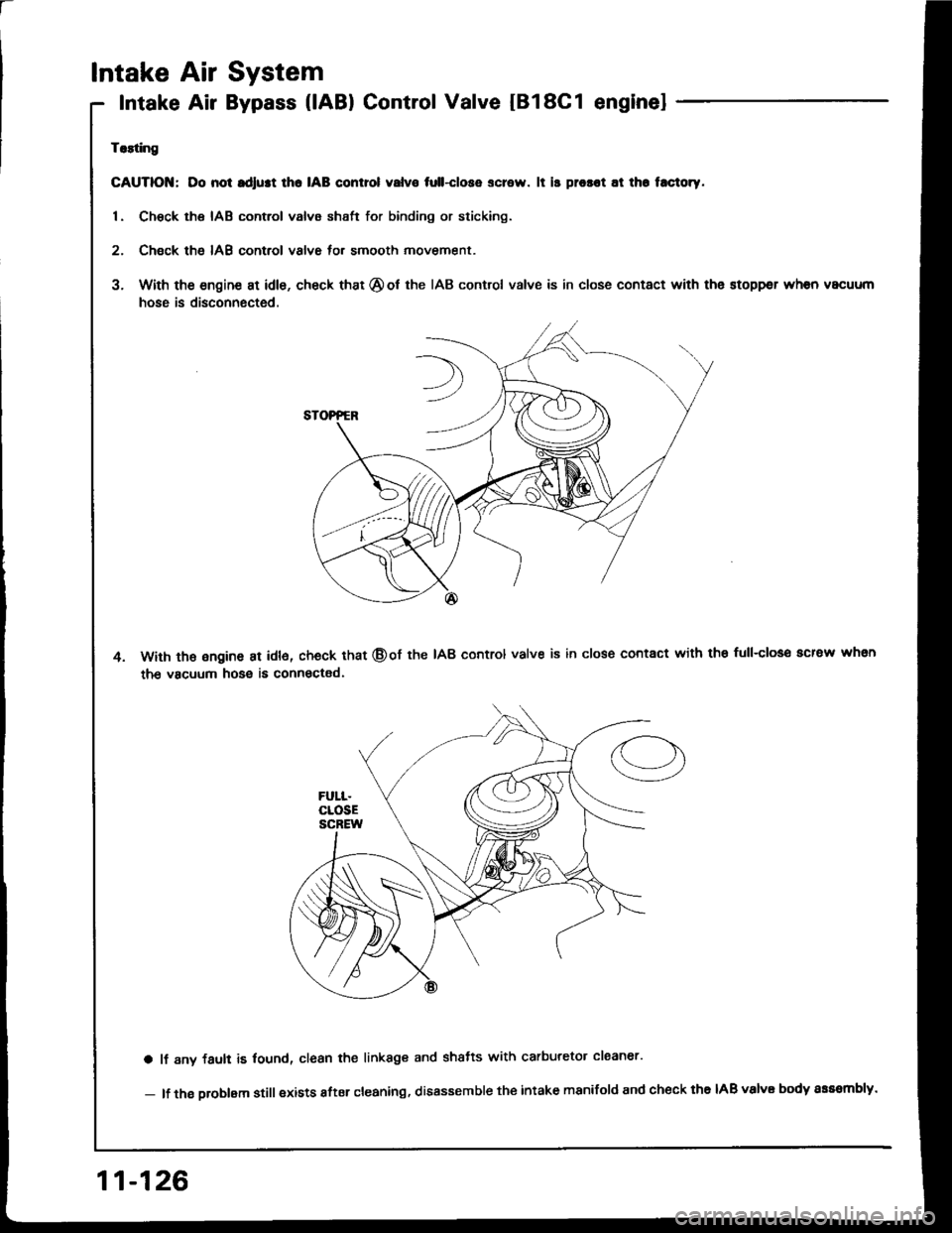
Trlting
GAUTIOI{; Do not rdlust lho IAB control valvo tull-close screw. lt is prosot at th. t.ctoty.
1. Chsck the IAB control valve shsft for binding or sticking.
2. Check th6 IAB control valve for smooth movement.
3. With the engine at idle, check that @ot the IAB control valve is in close contact with the stoppsr when vacuum
hose is disconnected.
With th€ ongine at idl6, check that @of the IAB control valve is in close contact with the full-closo acrew whsn
the vacuum hose is connectad.
a lf 8ny fault is lound, clean the linkage and shatts with carburetor claaner'
- lf the oroblam still exists after cleaning, disassemble the intake manifold and check the IAB valvE body sss8mbly.
11-126
Page 324 of 1413
A.
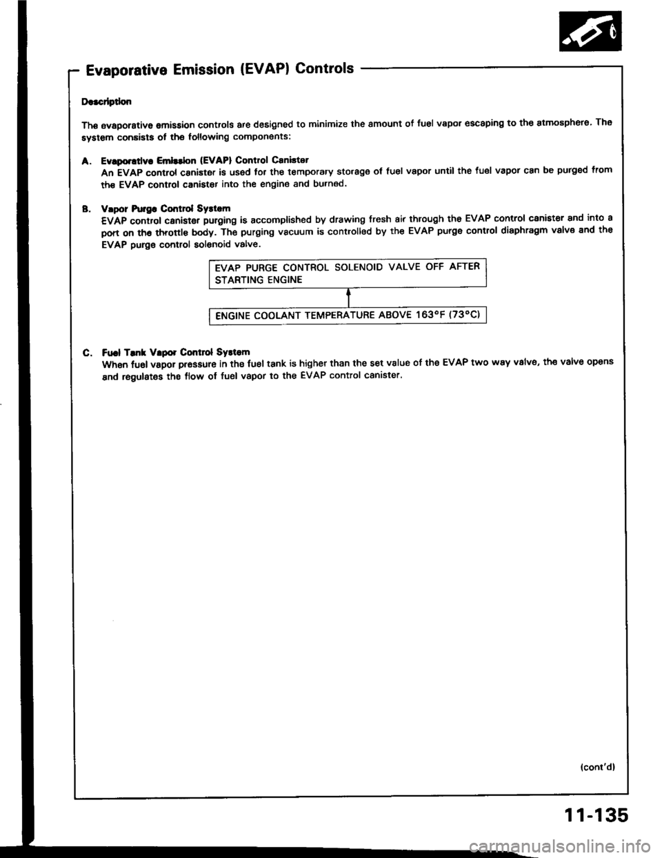
Evaporative Emission (EVAPI Controls
Da.cdptlon
Thg avaporstive omission controls are designed to minimize the smount of fusl vapor escaping to the atmosphero. The
system conaists ot the following compon€nts:
Evlporttly. Emlttbn (EVAPI Control Caniltot
An EVAP control canistor is used lor the temporary storage ot fuel vapor until the fuel vapor can be purged lrom
th€ EVAP control canister into the engin€ and burned.
vlpor hr]gG Cmt]ol Syst m
€VAp control canistgr puroing is accomplished by drawing fresh air through tho EVAP control canister and into a
pon on th6 throttl€ body. Th€ purging vacuum is controllsd by the EVAP purge control diaphragm valve end the
EVAP purge control solenoid valve.
C. Ft|.l Tmk Vlpor Control Systom
When fuel vapor prassure in the fuel tank is higher than the set v8lue of the EVAP two way v8lv6, th€ valve opens
and regulates the flow ol fuel vapor to the EVAP control canister.
(cont'd)
11-135
Page 326 of 1413
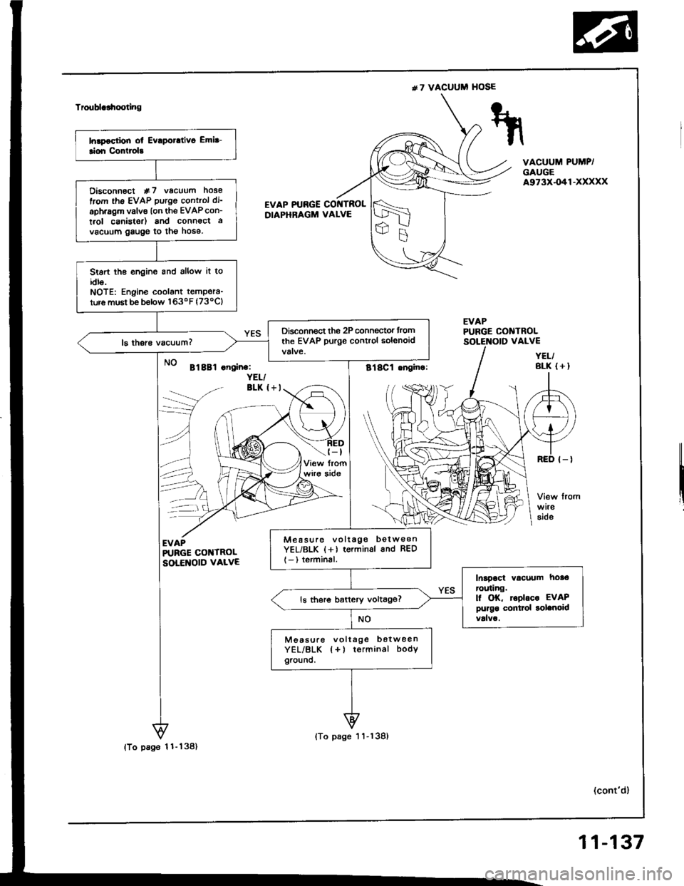
#7 VACUUM HOSE
Troublclhooting
VACUUM PUMP/GAUGEA973X-O41-XXXXX
EVAP PTJBGE COI{TROLDIAPHRAGM VALVE
EVAPPUBGE CONTROL
Bl8Bl .noin.:YEL/BLK I+I
(-t
wirg aide
--\
EVAPR'RGE COI{TROLSOLENOID VALVE
(cont'd)
VALVE
YEL/BLK (+I
Disconn€ct #7 vacuum hose
trom the EVAP putgo control di'
aph.agm valve lon the EVAPcon-
t.ol canistor) and connoct a
vacuum gauge to tho hose.
Stsrt the €ngine and allow it toidls.NOTE: Engine coolant tempera-
ture must be b€low 163oF (73ocl
Oisconnect the 2P connegtor trom
the EVAP purge control solenoid
Mea suro voltago betw€enYEL/BLK {+) terminsl 6nd RED
l-) terminal.
Inapact vacuum hoa€ror.ring.l| OK, toolrc. EVAPpurgo conttol solenoidls ther6 battery voltage?
Moasule voltage botweenYEL/BLK {+) terminal bodYground.
(To pa96 1 1- 138)
(To page 1 'l -139)
11-137
Page 328 of 1413
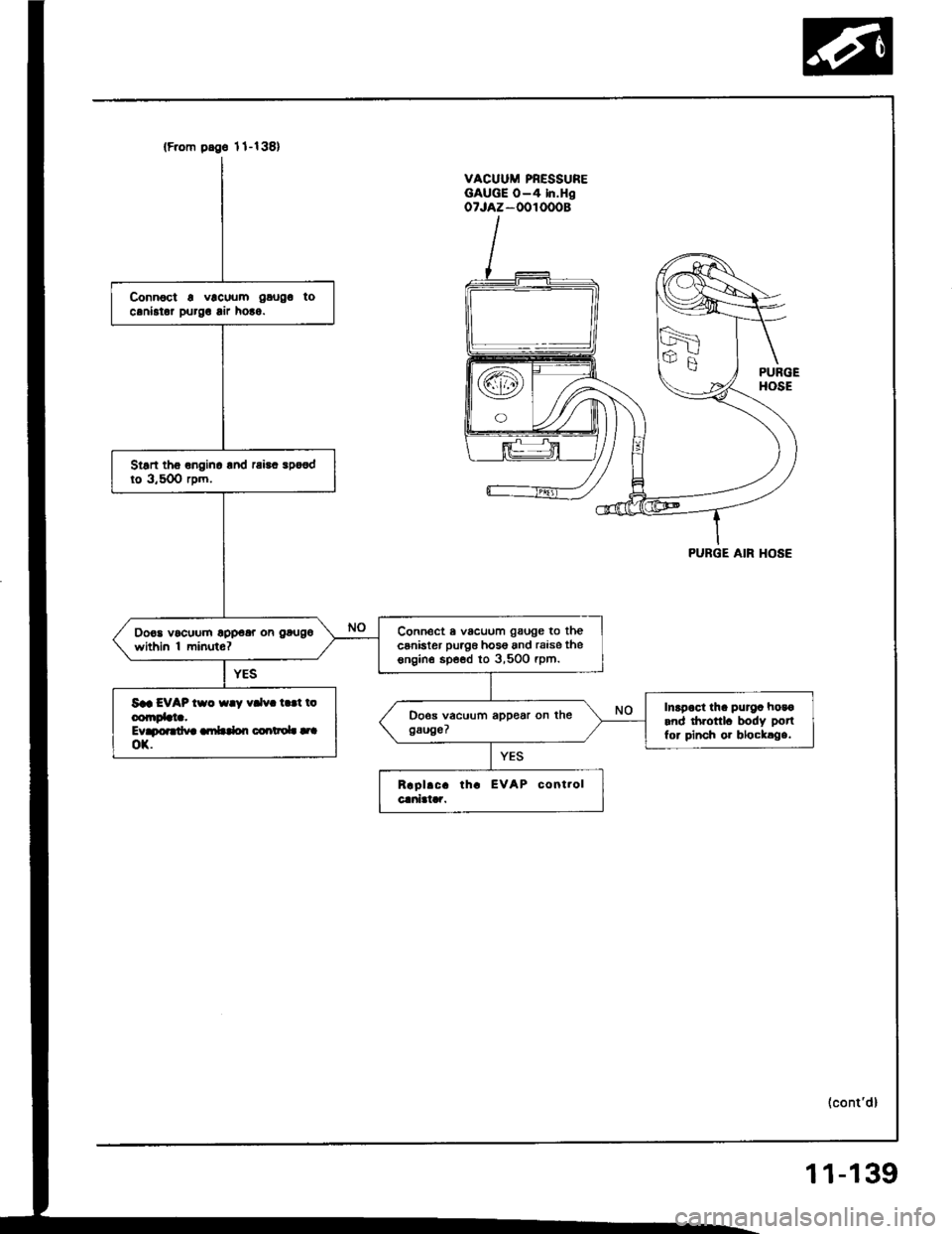
(F.om pdge 1l-138)
Connoct a vlcuum gaugo tocaniator purg! lir ho!o.
Stsn tho onginc lnd rai!. spo€dto 3,50O rpm.
Connect a vacuum gauge to thecsnister puag6 hos6 and raise thesngin€ spe€d to 3,500 rpm.
Do€a vocuum opp€ar on gougo
within 'l minuto?
Saa EVAP tso {ay vdv. t.!t ioconrDbta.Evapoardva ambdon coartaoL |.|ox.
Inapoct tha purga hosoand drronl. body potl
for pinch or blocklga.
VACUUM PRESSUREGAUGE O-4 In.HgoTJAZ-OOIOOOB
PURGE AIR HOSE
(cont'd)
11-139
Page 393 of 1413
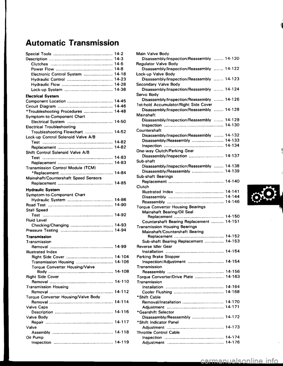
Automatic Transmission
'l4-2
14-3't 4-6
14-8
14-14
14-23
Hvdraulic Flow ...--...... 14-24
Lock-up System ........ 14-38
Eloctrical Systom
Component Location ............,...,................ I 4-45
Circuit Diagram ............. 14-46'Troubleshooting Procedures ........,..........., l4-48
Symptom-to-Component Chart
Electrical System ...... 14-50
Electrical Troubleshooting
Troubleshooting Flowchart .................... 14-52
Lock-uo Control Solenoid Valve A/8
Test .................. --.... \4-82
ReDlacement ,...,...,..,. 14-82
Shift Control Solenoid Vslve A/B
Test .................. ...... 14-83
Reolacement .............. 14-83
Transmission Control Module (TCM)*ReDlacement ........... 14-84
Mainshalt/CountershaJt SDeed Sensors
Reolacement ............. 14-85
Hydraulic Systom
Symptom-to-Component Chart
Hydraulic System
Road Test
Slall Speed
Test ..................
Fluid Level
Checking/Changing
Pressu.e Testing
Transmission
Transmission
Removal ............. ...... 14-99
lllustrated Index
Right Side Cover .................................. 1 4- 1 04
Transmission Housin9 ..................,,....... I 4-1 06
Torque Converter HousingNalve
Body .................. ... 14- 1O8
Right Side Cover
Removal ............. ...... 14-110
Transmission Housing
Removal ............. .-..-. 14-112
Torque Convener HousingNalve Body
Removal ............. ...... 14-114
Valve Caps
Description ................ 14-116
Valve Body
Repair ................ ...-.. 14-117
Valve
Assembly ...........
Oil Pump
Main Valve Body
Disassembly/lnspection/Reassembly
Regulator Valve Body
Disassembly/lnspection/Reassembly
Lock-up Valve Body
Disassembly/lnspection/Reassembly .......
Secondary Valve Body
Disassembly/lnspection/Reassembly .......
Servo Body
Disassembly/lnspection/Reassembly .......
1st-hold Accumulator/Right Side Covet
Oisassembly/lnspection/Reassembly .,..,..
Mainshaft
Disassembly/lnspection/Reassembly -.. -... 1 4- 1 29
lnsDection ................. 14- 130
Countershaft
Disassembly/lnspection/Reassembly ....... 14-132
Disassembly/Reassembly ....................... 1 4-1 33
lnsDection ................. 14-134
One-way Clutch/Parking Gear
Disassembly/lnspection .................... -.. -. 1 4-137
Sub-shaft
Disassembly/lnspection/Reassembly ....... 14-138
Disassemblv/Reassemblv ....................... 1 4-1 39
Sub-shaft Bearings
Replacement ............. l4-140
Clutch
fllustrated lndex ................. -..-...-.......... 14-1 41
Disassembly ,,,.,,........ 14-144
Reassembly .............. 14-146
Torque Converter Housing Bearings
Mainshaft Bearing/Oil Seal
Reolacement ......... 14-1 50
Countershaft Bearing Replacement .......,, 14-1 5l
Transmission Housing Bearings
Mainshsft/Countershaft Bearing
Repfacement ...-..-..14-152
Sub-shaft Bearing Replacement .............. 1 4-1 53
Reve.se ldler Gear
lnstallation ................ 14-154
Parking Brake Stopper
lnspection/Adjustment ..........................'14-'154
Transmission
Reassemblv .............,. .14_156
Toroue Converter/Drive Plate ..,..,............... 1 4- 1 63
Transmission
14-120
14-122
14-123
14-124
14-126
14-124
14-86
14-90
't4-92
14-93
14-94
lnstallation
Cooler Flushing'Shitt Cable
Removal/lnstallation ..............................
Adiustment ...-..-......-. 14-'171*Gearshift Selector
Disassembly/Reassembly .....................,. 1 4-17 2*Shift Indicator Panel
Adjustment -..........-...14-173
Throttle Control Cable
fnspection .......,..,...... 14-17 4
Adjustment .............. 14-176
14-164
14-168
14-'t 7 0
Inspection
Page 395 of 1413
The Automatic Transmission is a combination of a 3-e,ement torque convefter and triple-shaft electfonically controlled
automatic transmission which provides 4 speeds forward and 1 speed reverse. The entire unit is positioned in line with
the engine.
Torque Converter, Gears and Clutches
The torque converter consists of a pump, turbine and stator assembly in a single unit, The torque converter is connected
to the engine crankshaft so they turn together as a unit as the engine turns. Around the outside of the torque converter
is a ring gear which meshes with the starter pinion when the engine is being staned. The entire torque converter assem-
bly serves as a flywheel while transmitting power to the transmission mainshaft.
The transmission has three parallel shafts, the mainshaft. countershaft and sub-shaft. The mainshatt is in line with the
engine crankshaft.
The mainshaft includes the clutches for 1 st, and 2ndl4th, and gears for 3rd. 2nd, 4th, reverse and l st (3rd gear is in-
tegral with the mainshaft, while reverse gear is integral with the 4th gear).
The countershaft includes the 3rd clutch and gears Ior 3rd, 2nd,4th, reverse, lst and parking. Reverse and 4th gears
can be locked to the countershaft at its center, providing 4th gear or reverse, depending on which way the selector is moved.
The sub-shaft includes the lst-hold clutch and gears for 1st and 4th
The gears on the mainshait are in constant mesh with those on the countershaft and sub-shaft. When certain combina-
tions of gears in the transmission are engaged by the clutches, power is transmitted from the mainshaft to the counter-
shaft via the sub-shatt to provide @, E, tr. tr and @ position.
Electronic Control
The electronic control system consists of the Transmission Control Module {TCM), sensors, and 4 solenoid valves. Shift-
ing and lock-up are electronically controlled for comfortable driving under all conditions.
The TCM is located below the dashboard, behind the left side kick panel on the driver's side.
Hydraulic Control
The valve bodies include the main valve body, secondary valve body, regulator valve body. servo body, and lock-up valve
body throuqh the respective separator plates.
They are bolted on the torque converter housing.
The main valve body contains the manual valve, 1-2 shift valve, 2-3 shift valve, Clutch Pressure Cont.ol (CPC) valve,
4th exhaust valve, relief valve, and oil pump gears.
The secondary valve body contains the 4-3 kick-down valve,3-2 kick-down valve,2-3 orifice cont.ol valve, 3-4 shitt
valve, orifice control valve. modulator valve, and servo control valve
The regulator valve body contains the pressure regulator valve. lock-up control valve, torque converter check valve, and
cooler check valve.
The servo bodv contains the servo valve which is integrated with the reverse shift fork, throttle valve B, and accumulators.
The lock-ug valve bodv contains the lock-up shift valve and lock-up timing B valve. and is bolted on the secondary valve
body.
Fluid from the regulator passes through the manual valve to the various control valves.
Shitt Control Mochanism
Input to the TCM i.om various sensors located throughout the car determines which shift control solenoid valve should
be activated.
Activating a shift control solenoid valve changes modulator pressure, causing a shift valve to move. This pressurizes
a line to one of the clutches. engaging that clutch and its corresponding gear.
Lock-up Mechanism
In @ position. in 2nd, 3rd and 4th, and E position in 3rd, pressurized tluid can be drained from the back of the tor-
que converter through an oil passage, causing the lock-up piston to be held against the torque converter cover. As this
takes Dlace, the mainshaft rotates at the same speed as the engine crankshatt. Together with hydraulic control, the TCM
optimizes the timing ol the lock-up mechanism.
The lock-up valves control the range of lock-up according to lock-up control solenoid valves A and B, and throttle valve B
When lock-up control solenoid valves A and B activate, modulator pressure changes. Lock-up control solenoid valves
A and B are mounted on the torque converter housing, and are controlled by the TCM.
(cont'd)
14-3
Page 398 of 1413
Description
Clutches
The four speed automatic transmission uses hydraulically actuated clutches to engage or disengage the transmission gears.
When clutch pressure is introduced into the clutch drum, the clutch piston is applied. This presses the iriction discs and
steel plates together, locking them so they don't slip. Power is then transmitted through the engaged clutch pack tojts hub-mounted gear.
Likewise, when clutch pressure is bled from the clutch pack. the piston releases the friction discs and steel plates, and
they are {ree to slide past each other while disengaged. This allows the gear to spin independently on its shaft, transmit-
ting no power.
1st ClutchThe l st clutch engages/disengages 1st gear, and is located at the end of the mainshaft, just behind the right side cover.
The 1st clutch is supplied clutch pressure by its oil feed pipe within the mainshaft.
1st-hold clutchThe 1st-hold clutch engages/disengages 1st-hold or I Fosition, and is located at the center ol the sub-shaft. The 1st-
hold clutch is supplied clulch pressure by its oil feed pipe within the sub-shait.
2nd ClutchThe 2nd clutch engages/disengages 2nd gear, and is located at the center of the mainshaft. The 2nd clutch is joined
back-to-back to the 4th clutch. The 2nd clutch is supplied clutch pressure through the mainshaft by a circuit connected
to the regulator valve body.
3rd Clutch
The 3rd clutch engages/disengages 3rd gea.. and is located at the end oJ the countershaft, opposite the right side cover.
The 3rd clutch is supplied clutch pressure by its oil feed pipe within the countershaft,
4th clurch
The 4th clutch engages/disengages 4th gear. as well as reverse gear, and is located at the center of the mainshaft.
The 4th clutch is joined back-to-back to the 2nd clutch. The 4th clutch is supplied clutch pressure by its oil feed pipe
within the mainshalt.
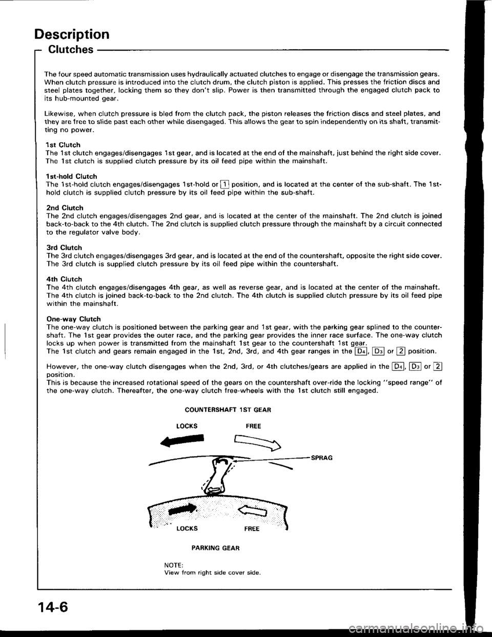
One-way Clutch
The one-way clutch is posjtioned between the parking gear and 1st gear. with the parking gear splined to the counter-
shaft. The 1st gear provides the outer race, and the parking gear provides the inner race surface. The one-way clutch
locks up when power is transmitted from the mainshaft 1st gear to the countershaft lst ggel _The 1st clutch and gears remain engaged in the 1st. 2nd. 3rd, and 4th gear ranges in the @, E or E position.
However, the one-way clutch disengages when the 2nd. 3rd, or 4th clutches/gears are applied in the E, lD.l o, Eoosttton.
This is because the increased rotational speed of the gears on the countershaft over-ride the locking "speed range" of
the one-way clutch. Thereafter, the one-way clutch free-wheels with the lst clutch still engaged.
COUNTERSHAFT 1ST GEAR
FREE
:>
LOCKS
aF
NOTE:View trom right side cover side.
14-6