body HONDA INTEGRA 1994 4.G Repair Manual
[x] Cancel search | Manufacturer: HONDA, Model Year: 1994, Model line: INTEGRA, Model: HONDA INTEGRA 1994 4.GPages: 1413, PDF Size: 37.94 MB
Page 475 of 1413
Shift Control Solenoid ValveA/B
Test
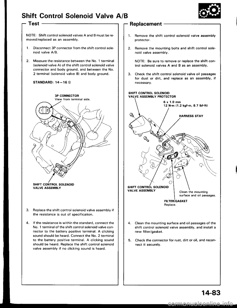
NOTE: Shift controlsolenoid valves A and B must be re-
moved/replaced as an assembly.
1.Disconnect 3P connector from the shitt control sole-
noid valve A/8.
Measure the resistance between the No. 1 terminal(solenoid valve A) of the shift control solenoid valve
connecto. and body ground, and between the No.
2 terminal (solenoid valve B) and body ground.
STANDARD: 14- 16 O
SHIFT CONTROL SOLENOIOVALVE ASSEMBLY
Replace the shift control solenoid valve assembly if
the resistance is out oI sDecificaiton.
lf the resistance is within the standard, connect the
No. 1 terminalof the shift controlsolenoid valve con-
nector to the battery positive terminal. A clicking
sound should be heard. Connect the No. 2 terminal
to the battery positive terminal. A clicking sound
should be heard. Replace the shift control solenoid
valve assembly if no clicking sound is heard.
3.
1.Remove the shift control solenoid vaive assembly
protector.
Remove the mounting bolts and shift control sole-
noid valve assembly.
NOTE: Be sure to remove or replace the shitt con-
trol solenoid valves A and B as an assembly.
Check the shitt control solenoid valve oil passages
for dust or dirt, and replace as an assembly, it
necessary.
Clean the mounting surface and oil passages of the
shitt control solenoid valve assembly, and install a
new filter/gasket.
Check the connector for rust, dirt or oil, and recon-
nect it securely.
6 x 1.0 mm12 N'm (1.2 kgl.m,4.7 lbl.ftl
VALVE ASS€MBLYClean the mountingsurface and oil passages.
Replace.
14-83
Page 481 of 1413
NOTES
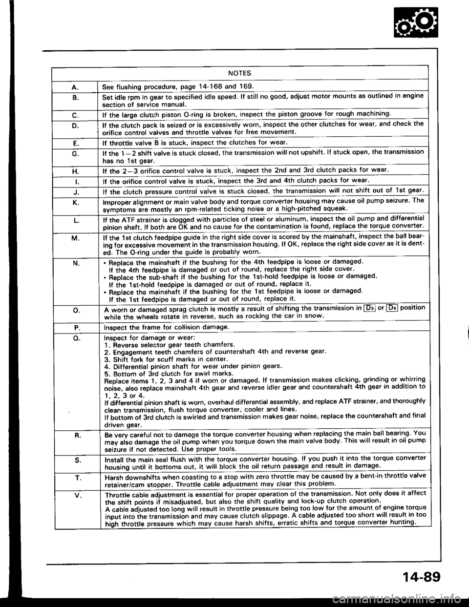
A.See flushing procedure, page l4-168 and 169.
B.Set idle rpm in gear to specitied idle speed. lf still no good, adiust motor mounts as outlined in engine
section of service manual.
lf the large clutch piston O-ring is broken, inspect the piston groove for rough machining.
lf the clutch pack is seized or is excessively worn, inspect the other clutches Jor wear, and check the
orifice control valves and throttle valves for free movement.
E.It throttle valve B is stuck, inspect the clutches for wear.
lf the 1-2 shift valve is stuck closed, the transmission will not upshift. lI stuck open, the transmission
has no lst gear.
H.lf the 2-3 orifice control valve is stuck, inspect the 2nd and 3rd clutch packs for wear.
ll the orifice cont.ol valve is stuck, inspect the 3rd and 4th clutch packs for wear.
lf the clutch Dressure control valve is stuck closed, the transmission will not shilt out of 1st gear.
K.improper alignment or main valve body and torque converter housing may cause oil pump seizure. The
symptoms ale mostly an rpm-related ticking noise or a high-pitched squeak.
L.ll the ATF strainer is ctogged with panicles of steel or aluminum, inspect the oil pump and ditferential
pinion shaft. lt both are OK and no cause lor the contamination is found, replace the torque converter.
M.lf the 1st clutch feedpipe guide in the right side cover is scored by the mainshaft, inspect the ball bear-
ing for excessive movement in the transmission housing. lf OK. replace the right side cover as it is dent-
ed. The O-ring under the guide is probably worn.
N.ReDlace the mainshstt if the bushing for the 4th feedpipe is loose or damaged.
It the 4th feedpipe is damaged or out ot tound, replace the right side cover'
Replace the subjshaft it thtbushing for the 1st-hold Jeedpipe is loose or damaged.
lf the 1st-hold feedpipe is damaged or out of round, replace it.
Replace the mainshaft if the bushing lor the 1st feedpipe is loose or damaged.
lf the lst feedpipe is damaged or out ot round, replace it.
o.A *o- r, da."s"d "p-g clutch is mostly a result of shifting the transmission in El or Lq! position
while the wheels rotate in reverse, such as rocking the car in snow.
P.InsDect the frame for collision damage.
o.Inspect for damage or wear:
1. Reverse selector gear teeth chamfers.
2. Engagement teeth chamters of countershaft 4th and reverse gear.
3. Shift fork for scutt marks in center.
4. Differential Dinion shaJt for wear under pinion gears.
5. Bottom of 3rd clutch for switl marks.
Replace items 1 , 2, 3 and 4 it worn or damaged. lf transmission makes clicking, grinding or.whirring
noise, atso replace mainshaft 4th gear and reverse idler gear and countershaft 4th gear in addition to
1,2,3ot4.lf ditiersntial Dinion shaft is worn, overhaul differential assembly, and replace ATF strainel, and thoroughly
clean transmission, tlush torque convertet, cooler and lines.
lf bottom of 3rd clutch is swirled and transmission makes gear noise, replace the countershaft and tinal
driven gear.
R.Be wry careful not to dsmage the torque converter housing when replacing the main ballbearing. You
may al;o damage the oil pump when you torque down the main valve body. This will result in oil pump
seizure it not detected. Use proper tools.
qInstall the main seal tlush with the torque converter housing, lf you push it into the torque converter
housing until it bottoms out. it will block the oil return passage and result in damage.
T,Harsh do\/vnshiJt"\./l,'hen coasting to a stop with zero th.ottle may be caused by a bent-in throttle valve
retainer/cam stopper. Throttle cable adjustment may clear this problem.
ifuitle cable adjustment is essential for proper operation of the transmission. Not only does it affect
the shift points if misad,usted, but also the shift quality and lock-up clutch operation'
A cable adjusted too long will result in throttle pressure being too low for the amount of engine torque
input into ihe trsnsmission and may cause clutch slippage. A cable adjusted too short will result in too
hi;h throttle pressure which may cause harsh shitts, erratic shrfts and torque con
14-89
Page 499 of 1413
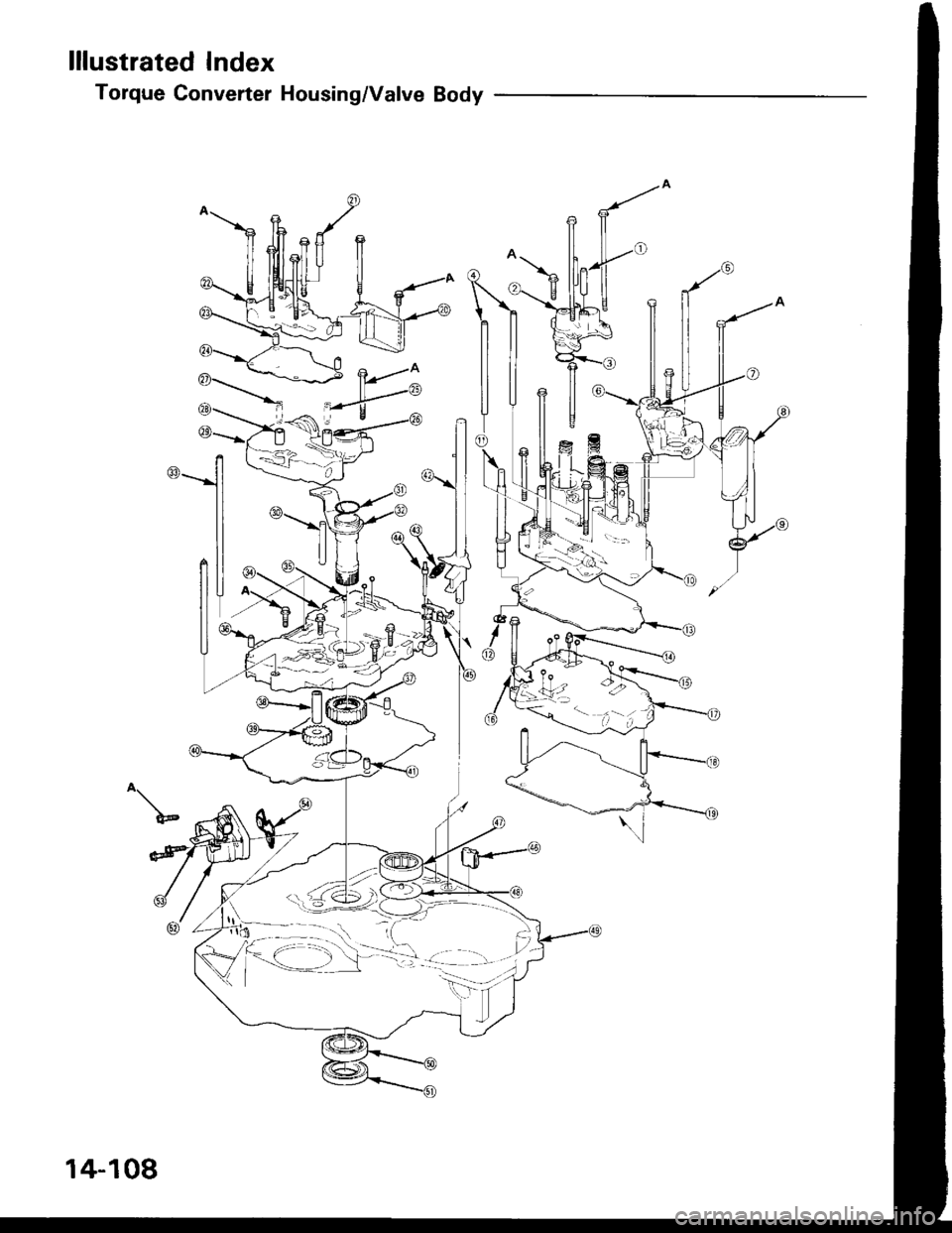
lllustrated Index
Torque Converter Housing/Valve Body
^\
14-108
Page 500 of 1413
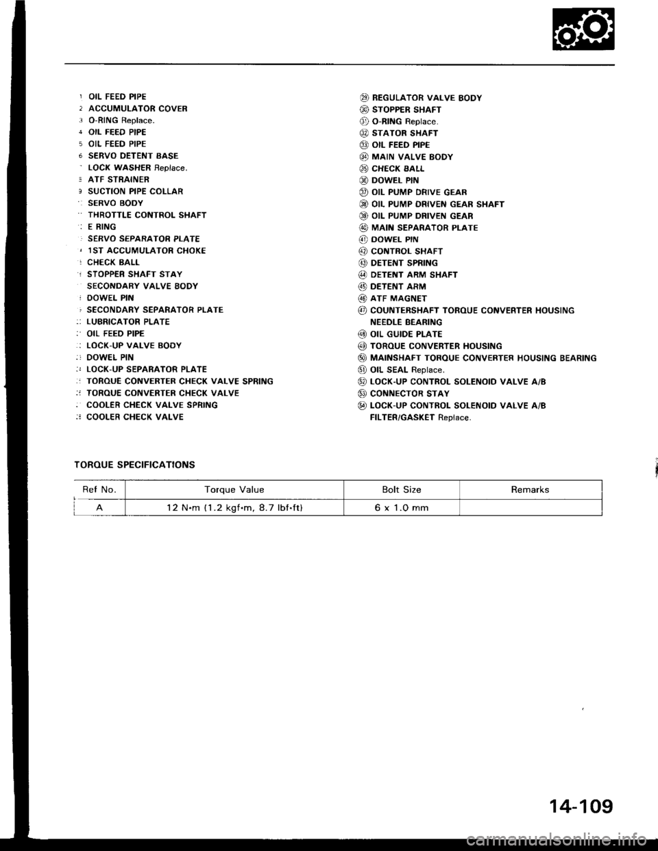
OIL FEED PIPE
ACCUMULATOR COVER
O-RING Replace.
OIL FEED PIPE
OIL FEED PIPE
SERVO OETENT EASE
LOCN WASHER Feplace.
ATF STRAINER
SUCTION PIPE COLLAR
SERVO BOOY
THROTTLE CONTROL SHAFT
E RING
SERVO SEPARATOR PLATE
1ST ACCUMULATOR CHOKE
CHECK BALL
STOPPER SHAFT STAY
SECONDARY VALVE BODY
DOWEL PIN
SECONDARY SEPARATOR PLATE
LUBRICATOR PLATE
OIL FEED PIPE
LOCK.UP VALVE BODY
DOWEL PIN
LOCK-UP SEPARATOR PLATE
TOROUE CONVERTER CHECK VALVE SPRING
TOROUE CONVERTER CHECK VALVE
COOLER CHECK VALVE SPRING
COOLER CHECK VALVE
TOROUE SPECIFICATIONS
@ REGULAToR vALvE BoDY
@ STOPPER SHAFT
@ O-RING Reptace.
@ STATOR SHAFT
@ otl FEED PIPE
@ MAIN vALvE BoDY
@ CHECK EALL
@ DowEL PIN
@ oIL PUMP DRIVE GEAR
@ OIL PUMP DRIVEN GEAR SHAFT
Q9 OIL PUMP DRIVEN GEAR
@ MAIN SEPARAToR PLATE
@ DowEL PrN
@ coNTBoL sHAFT
@ DETENT SPRING
@ DETENT ARM SHAFT
@) DETENT ARM
@ ATF MAGNET
@ COUNTEBSHAFT TOROUE CONVERTER HOUSING
NEEDLE BEANING
@ oIL GUIDE PLATE
@ TOROUE CONVERTER HoUSING
@) MAINSHAFT TOROUE CONVERTER HOUSING BEARING
@ oll SEAL Reptace.
@ LocK-up coNTRoL soLENotD vALvE A/B
@ coNNECTOR STAY
@ LOCK-UP CONTROL SOLENOTD VALVE A/B
FILTER/GASKET Replace.
ReI No.Torque ValueBolt SizeRemarks
12 N.m (1 .2 kgf.m, 8.7 lbf.ft)6 x 1.O mm
14-109
Page 505 of 1413
![HONDA INTEGRA 1994 4.G Repair Manual Torque Gonverter Housing/Valve Body
Removal
\LOCK-UP VALVE llB.DY\u
Bolts, 7
DOWEL PIN
otLFEEDPIPES
A
Ll
ll|i
|]V
OII- FEED PIPES
LOCK-UP SEPARATORPI.ATE
TOR COVER
OIL FEEO PIPE
8oll3.3
ATF STRAINER
S HONDA INTEGRA 1994 4.G Repair Manual Torque Gonverter Housing/Valve Body
Removal
\LOCK-UP VALVE llB.DY\u
Bolts, 7
DOWEL PIN
otLFEEDPIPES
A
Ll
ll|i
|]V
OII- FEED PIPES
LOCK-UP SEPARATORPI.ATE
TOR COVER
OIL FEEO PIPE
8oll3.3
ATF STRAINER
S](/img/13/6067/w960_6067-504.png)
Torque Gonverter Housing/Valve Body
Removal
\LOCK-UP VALVE llB.DY\u
Bolts, 7
DOWEL PIN
otLFEEDPIPES
A
Ll
ll|i
|]V
OII- FEED PIPES
LOCK-UP SEPARATORPI.ATE
TOR COVER
OIL FEEO PIPE
8oll3.3
ATF STRAINER
SERVO DETENTBASEREGULATOR VALVEAODY
OIL FEED PIPES
DOWEL PIN
OIL PUMP DRIVEN GEAR SHAFT
OIL PUMP DRIVEN
SECONDARY VALVEBODY
DOWEL PIN
SECONDARY SEPARATORPLATE
SUCTION PIPECOLLAR
MAIN S€PARATORPLATE
ft-- rrr urcler
TOROUE CONVERTERHOUSING
8olts, 4 Boll
MAIII VALVEBODY
14-114
Page 506 of 1413
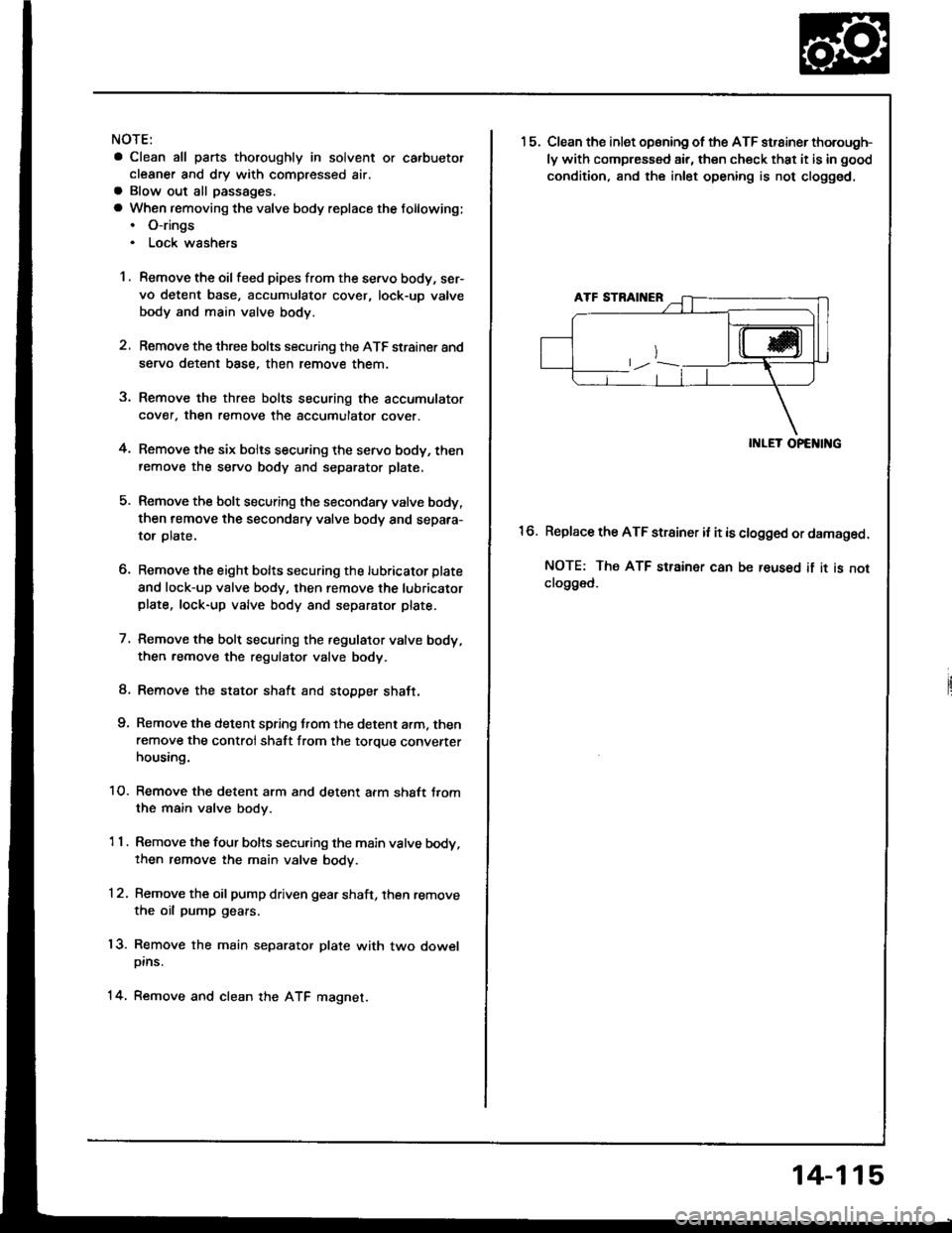
NOTE:
a Clean all parts thoroughly in solvent or carbuetor
cleaner and dry with compressed air.a Blow out all passages.
a When removing the valve body replace the following:. O-rings. Lock wsshers
1 . Remove the oil feed pipes from the servo body, s€r-
vo detent base, accumulatof cover, lock-uD valve
body and main valve body.
2, Remove the three bolts securing the ATF strainer and
servo detent base, then remove them.
3. Remove the three bolts securing the accumulator
cover. then remove the accumulator cover.
4. Remove the six bolts secu.ing the servo body, then
remove the servo body and separator plate.
5. Remove the bolt securing the secondary valve body,
then remove the secondary valve body and separa-
tor plate.
6. Remove the eight bolts securing the lubricator plate
and lock-up valve body, then remove the lubricatorplate, lock-up valve body and separator plate.
7. Femove the bolt securing the.egulator valve body,
then.emove the regulator valve body.
8. Remove the stator shaft and stopper shaft.
9. Remove the detent spring t,om the detent arm. thenremove the control shaft from the torque convenerhousing.
1O. Remove the detent arm and detent afm shaft t.om
the main valve bodv.
1 1 . Remove the four bolts secu.ing the main valve body,then remove the main valve body.
12. Remove the oil pump driven gear shaft, then remove
the oil pump gears.
'13. Remove the main separator plate with two dowelDtns.
14, Remove and clean the ATF magnet.
15.Clean the inlet opsning of the ATF strainer thorough-
ly with compressed air, then check that it is in good
condition, and the inlet opening is not clogged.
II{LET OPENING
Replace the ATF strainer it it is clogged or damaged.
NOTE: The ATF strainer can be reused if it is notclo9ged.
16.
14-115
Page 507 of 1413
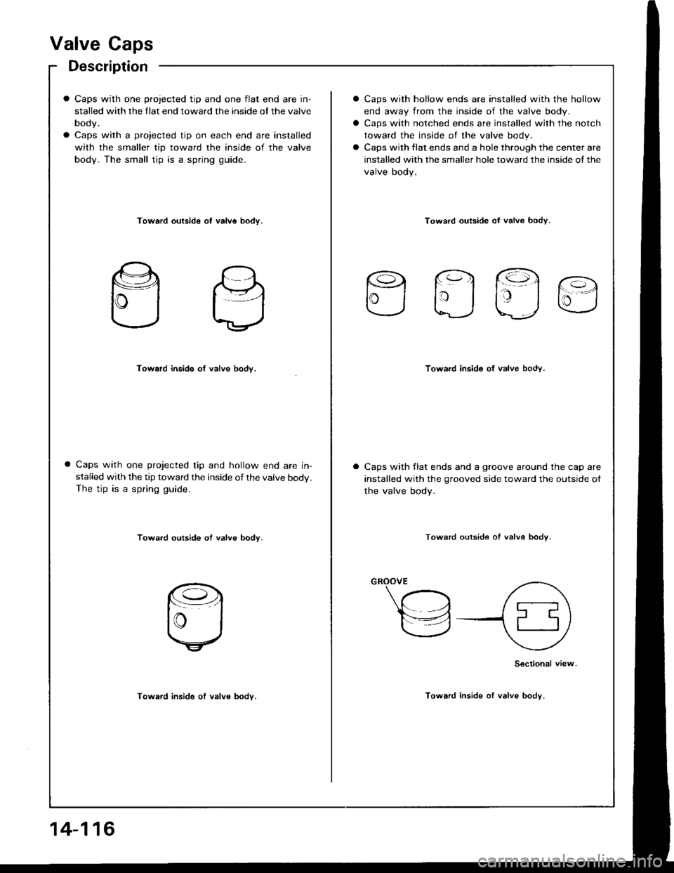
Valve Caps
Description
Caps with one projected tip and one flat end are in-
stalled with the llat end toward the inside ot the valve
body.
Caps with a projected tip on each end are installed
with the smaller tip toward the inside of the valve
body. The small tip is a spring guide.
Caps with hollow ends are installed with the hollow
end away from the inside of the valve body.
Caps with notched ends are installed with the notch
toward the inside of the valve body.
Caps with flat ends and a hole through the center are
installed with the smaller hole toward the inside of the
valve body.
Toward outside ot valv6 bodv.Toward outside oI valv€ bodv.
rq fq1 @.
lrj taj u
Toward inside of valve body.Towa.d inside of valve body.
Caps with one projected tip and hollow end are in-stalled with the tip toward the inside of the valve body.The tip is a spring guide.
Caps with llat ends and a groove around the cap are
installed with the grooved side toward the outside of
the valve body.
Towa.d outside ot valve body.Toward outside of valve bodv.
Toward inside of valve body.
Sectional view
Toward inside of valve body.
14-116
Page 508 of 1413
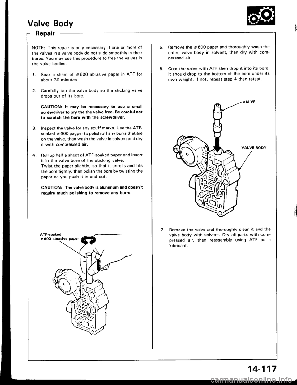
Valve Body
Repair
NOTE: This repair is only necessary il one or more of
the valves in a valve body do not slide smoothly in their
bores. You may use this procedure to lree the valves in
the valve bodies.
1. Soak a sheet of #600 abrasive paper in ATF for
about 30 minutes.
2. Carefully tap the valve body so the sticking valve
drops out of its bore.
CAUTION: lt may be necessary to use a small
screwdiiver to pry the the valve lree. Be carelul not
to sclatch the bore with ihe sc.ewdliver.
3. Inspect the valve tor any scuff marks. Use the ATF-
soaked # 600 pagper to polish off any burrs that are
on the valve, than wash the valve in solvent and dry
it with compressed air.
4. Roll up halt a sheet oI ATF-soaked paper and insert
it in the valve bore of the sticking valve.
Twist the paper slightly, so that it unrolls and fits
the bore tightly, then polish the bore by twisting the
paper as you push it in and out.
CAUTION: The valve body is aluminum and doesn't
require much polishing to remove any burs.
W
5.
6.
7.
Remove the #600 paper and thoroughly wash the
entire valve body in solvent, then dry with com-
perssed air.
Coat the valve with ATF then drop it into its bore.
It should drop to the bottom o{ the bore under its
own weight. lf not. repeat step 4 then retest.
VALVE BODY
Remove the valve and thoroughly clean it and the
valve body with solvent. Dry all parts with com
pressed air, then reassemble using ATF as a
lubricant.
14-117
Page 509 of 1413
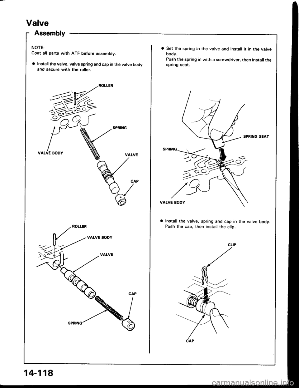
Valve
Assembly
NOTE:
Coat all parts with ATF belore assemblv.
a Install the valve, valve spring and cap in the valve bodyand secure with the 10116r.
ROLLER
VALVE BODY
ROLLER
VALVE EODY
VALVE
5-1-6^<
CAP
14-118
a Set the spring in the valve and install it in the valvebody.
Push the spring in with a screwdriver, then installthespring seat.
SPBING SEAT
VALVE BODY
Install the valve, spring and cap in the valve bodv.Push the cap, then install the cliD,
Page 510 of 1413
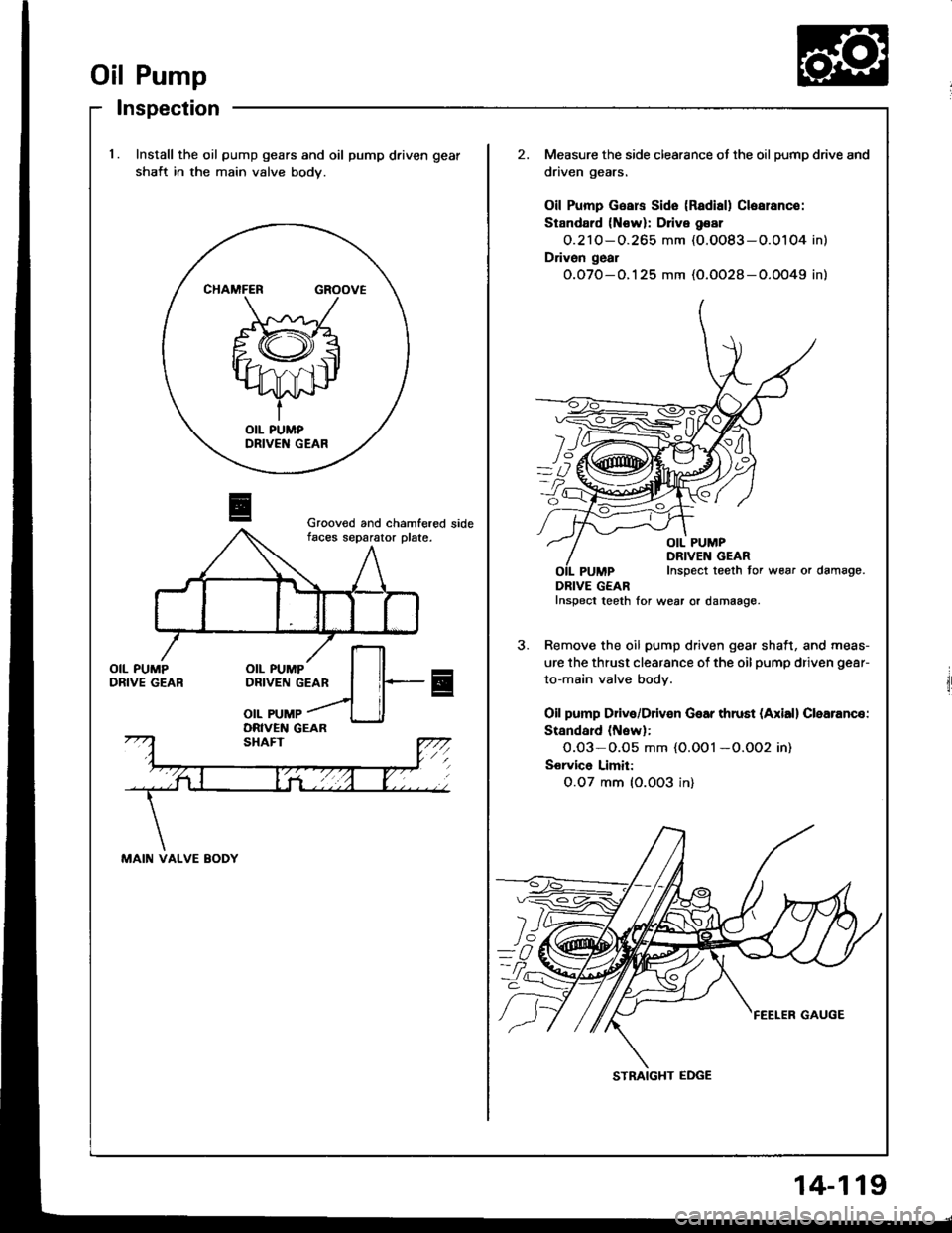
Oil Pump
lnspection
l.Install the oil pump gears and oil pump driven gear
shait in the main valve body.
Measure the side clearance ot the oil pump drive and
driven gears.
Oil Pump Gsars Sido (Radisl) Clsarance:
Stsndard {N€w}: Drive g€ar
O.21O-O.265 mm (O.OO83-O.O104 in)
Drivon g6al
O.O7O-O.125 mm (O.OO28-O.OO49 in)
YI
OIL PUMPDRIVEN GEARInspect teeth tor wear or damago.
DRIVE GEARInspect teeth lor wear or damaage.
Remove the oil pump driven gear shaft, and meas-
ure the thrust clearance of the oil pump driven gear-
to-main valve body.
Oil pump Drive/Driven Gear thrust (Axiall Clearance:
Standard (Nawl:
0.03-O.O5 mm {O.OOl -O.OO2 in)
Sorvice Limit:
O.O7 mm {O.0O3 in}
CHAMFER GROOVE
Grooved and chamfered sidefaces separator plate.
MAIN VALVE BODY
STRAIGHT EDGE
14-119