body HONDA INTEGRA 1994 4.G Repair Manual
[x] Cancel search | Manufacturer: HONDA, Model Year: 1994, Model line: INTEGRA, Model: HONDA INTEGRA 1994 4.GPages: 1413, PDF Size: 37.94 MB
Page 415 of 1413
Hydraulic Control
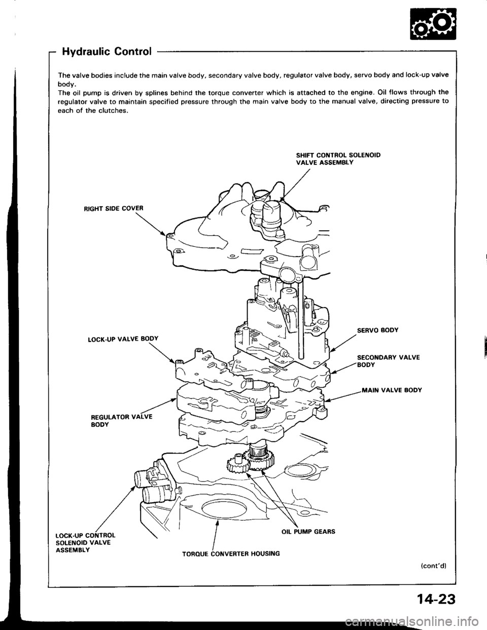
The valve bodies include the main valve body, secondary valve body, regulator valve body, servo body and lock-up valve
body.
The oil pump is driven by splines behind the torque converter which is attached to the engine. Oil flows th.ough the
regulator valve to maintain specified pressure through the main valve body to the manual valve, directing pressure to
each of the clutches,
SHIFT CONTROL SOLEIIOIDVALVE ASSEMBLY
RTGHT SIDE COVER
LOCK.UP VALVE BODY
VALVE BODY
REGULATOR VBODY
SOLENOID VALVEASSEMBLY
4<.__i: )o.-
OIL PUMP GEARS
14-23
Page 416 of 1413
Description
Hydraulic Control (cont'dl
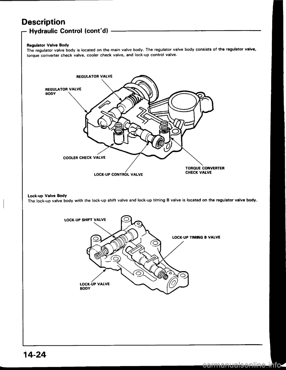
Ragularol Valve Body
The .egulator valve body is located on the main valve body. The regulator valve body consists of th€ regulator valva,
toroue converter check valve, cooler check valve, and lock-up contlol valve.
REGULATOR VALVE
REGULATOR VALVEBODY
COOLER CHECK VALVE
LOCT.UP CONTROI. VALVE
TONOUE COI{VERTEBCHECK VALVE
Lock-up Valvo Body
The lock-up valve body with the lock-up shilt valve and lock-up timing B valve is located on th€ regulator volvs body.
LOCK.UP SHIFT VALVE
TIMITG B VALVE
14-24
Page 418 of 1413
Description
Hydraulic Control (cont'dl
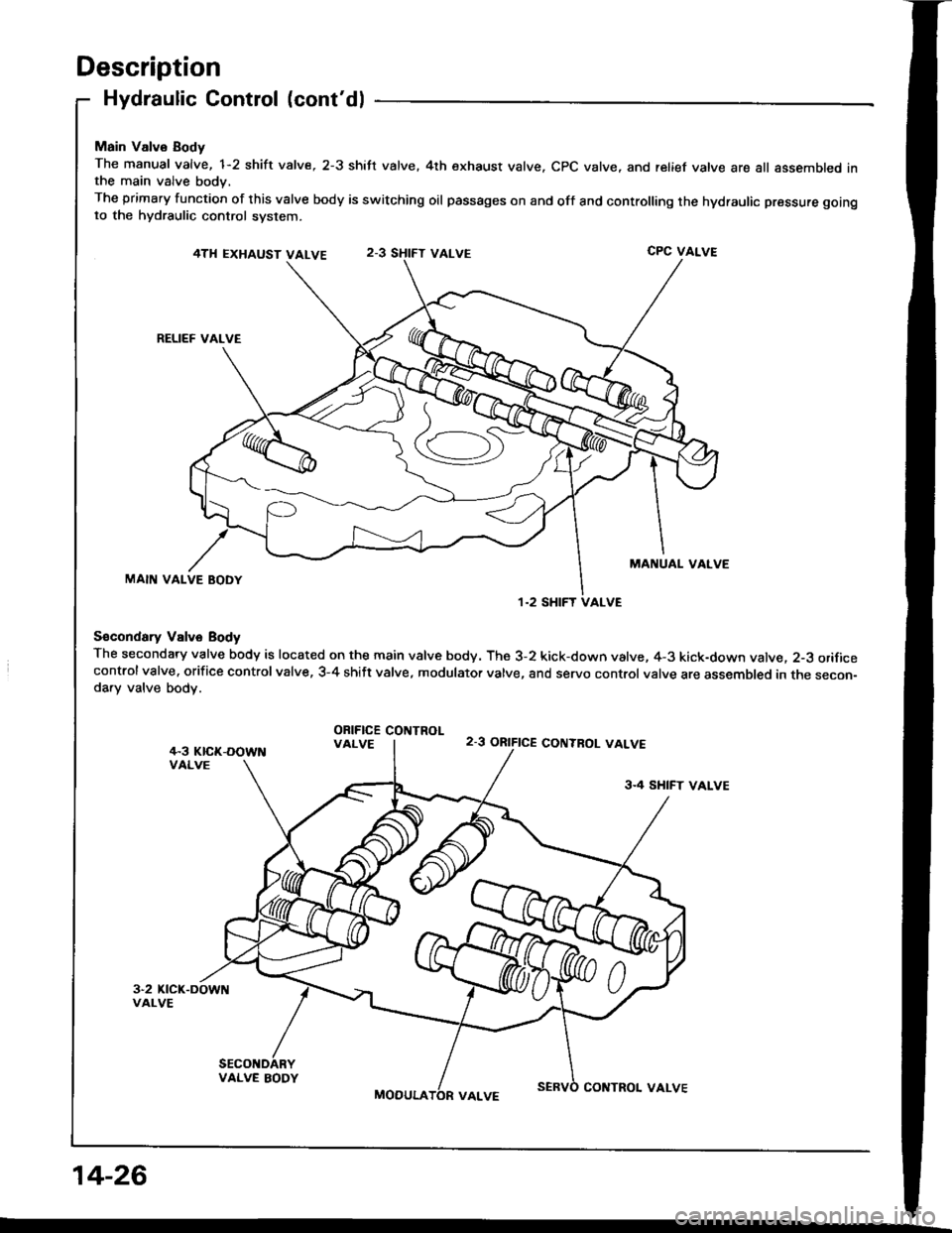
Main Valvo Body
The manual valve, 1-2 shift valve, 2-3 shift valve. 4th exhaust valve. CPC valve, and relief vatve are all assembled inthe main valve body,
The primary function of this valve body is switching oil passages on and off and controlling the hydraulic pressure gotngto the hydraulic control system.
4TH EXHAUST VALVECPC VALVE
RELIEF VALVE
MANUAL VALVEMAIN VALVE BODY
S€condary Vslve Body
The secondary valve body is located on the main valve body. The 3-2 kick-down valve, 4-3 kick-down valve. 2-3 orificecontrolvalve. orifice controlvalve, 3-4 shift valve, modulator valve, and servo control valve are assembled in the secon-da.y valve body.
ORIFICE COIITROLVALVE2-3 ORIFICE CONTBOL VALVE
3.4 SHIFT VALVE
VALVE BODY
MOOULACOITTROL VALVE
1.2 SHIFT VALVE
14-26
Page 419 of 1413
S6rvo Body
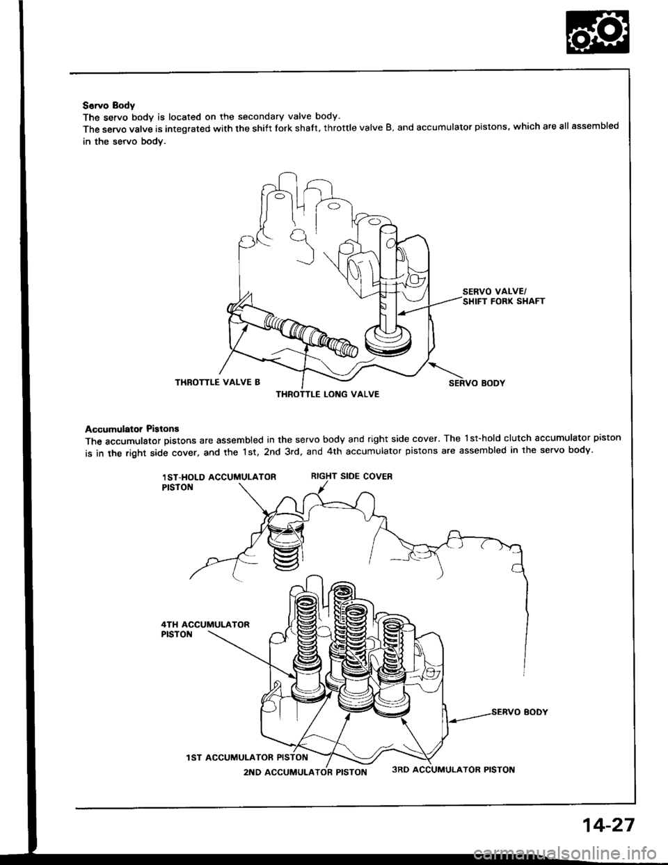
The servo bodv is located on the secondary valve body.
The servo valve is integrated with the shiit fork shatt, throttle valve B. and accumulator pistons, which are all assembled
in the servo bodv.
SERVO VALVE/SHIFT FORK SHAFT
THROTTLE VALVE BSERVO BODY
Accumulator Pislons
The accumulator pistons are assembled in the servo body and right side cover. The l st-hold clutch accumulator piston
is in the right side cover, and the 1st, 2nd 3rd, and 4th accumulator pistons are assembled in lhe servo body.
RIGHT SIDE COVER
THROTTLE LONG VALVE
1ST-HOLD ACCUMULATOR
4TH ACCUMULATOR
IST ACCUMUI-ATOR
2ND ACCUMULATOR PISTON3RD ACCUMULATOR PISTON
14-27
Page 459 of 1413
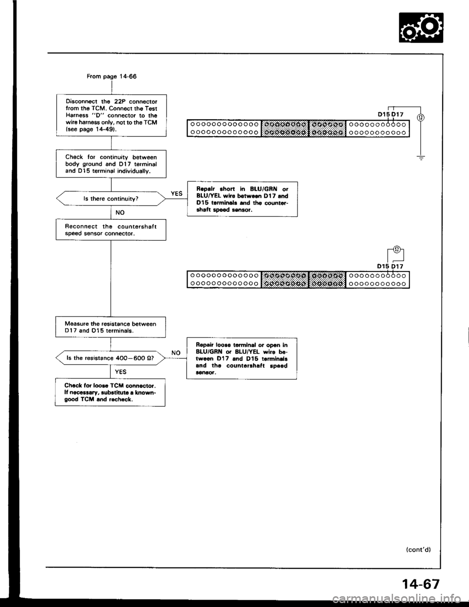
Disconnoct the 22P connectortrom the TCM. Connecr tho T€stHarness "D" connector to thewhe harness onlv, not to the TCMlsee page '14-49).
Check for continuitv betweenbody ground and 017 terminaland D15 terminsl individually.
Rgpllr short in BLU/GRI{ otBLU|/EL wlro b€twgon Dl7 andDl5 torminsla and ths countar-rhaft apo€d sengor.
Reconnect the countershaftsDe00 sensor connector.
Msasure the rgsistance betweenD 1 7 and 015 terminals.
Rgpair looa6 ta.minsl or opon in8LU/GRN o. 8LU/YEL wiro bo-trvaon D'17 and D15 tormindgand tho count6rlhafl !p6gd!€ntor,
ls the r€sistance 4OO-600 07
Ch6ck for looaa TCM conn6cto..ll nocaslrry, aubrlitut6 a known-good TCM a.d .6ch.ck.
(cont'd)
4-67
Page 464 of 1413
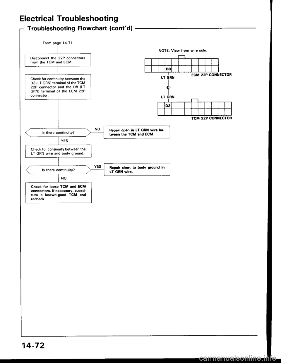
Electrical Troubleshootang
Troubleshooting Flowchart (cont'd)
From page '14-71
TCM 22P CONNECTOR
Disconnect the 22P connectorslrom the TCM and ECM.
Check for continuity between theD3 {LT GRN) terminal ol the TcM22P connecror and the D8 ILTGRN) terminal of the ECM 22Pconnector.
Ropai. opon In LT GRN rvi.a b.-twoon tho TCM and ECM.
Check lor continuity between theLT GRN wire and body ground.
Ropair short lo body ground inLT GRN wir6.
Ch€ck lor loos6 TCM and ECMconnectors, lf necessary, aubari-tute a known-good TCM andrccheck.
NOTE: View from wire side.
ECM 22P COiINECTOR
14-72
Page 467 of 1413
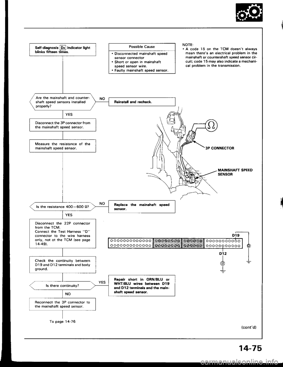
Possible Cause
. Disconnected mainshaft speedsensor connecror. Short or open in mainshaltspeed sensor wrre.. Faulty mainshatt speed sensor.
NOTE:. A code 15 on the TCM doesn't alwsysmean there's an electrical problem in themainshaft or countershaft speed sensor cir-cuit; code '15 may also indicate a mechani-cal Droblem in the transmission.
3P CONNECTOR
II o o o o o o o oo o o o o I:OtlO$O$g:Sl!:OlXOl*Ofill o o o o o o o o o O o | |
I ooooooooooooo l Sciii:ddii:ijii:l:i$idi$;d6#:l o oooop oo ooo | 6
"-f
1-L(0)Y-!
(cont'd)
solf-diagnosis E indicator lightblink tiftoon timos.
Are the mainshaft and counter-shalt speed sensors installedproperly?
Disconnect the 3P connector lromthe mainshaft speed sensor.
Measure the resistance ot themainshaft speed sensor.
ls the resistance 4OO-600 O?
Disconnect the 22P connectorfrom the TCM.Connect the Test Harness "D"
conneclor to the wire harnessonly, not ot the TCM (see page14-49).
Check the continuity betweenD19 and D12 terminals and bodyground.
Rcoair short in ORN/BLU otWHT/BLU wiros botween Dlgand Dl2 to.minals and tho main-shatt speod ronsor.
Reconnect the 3P connector tothe mainshatt speed sensor,
To page 14-76
14-75
Page 469 of 1413
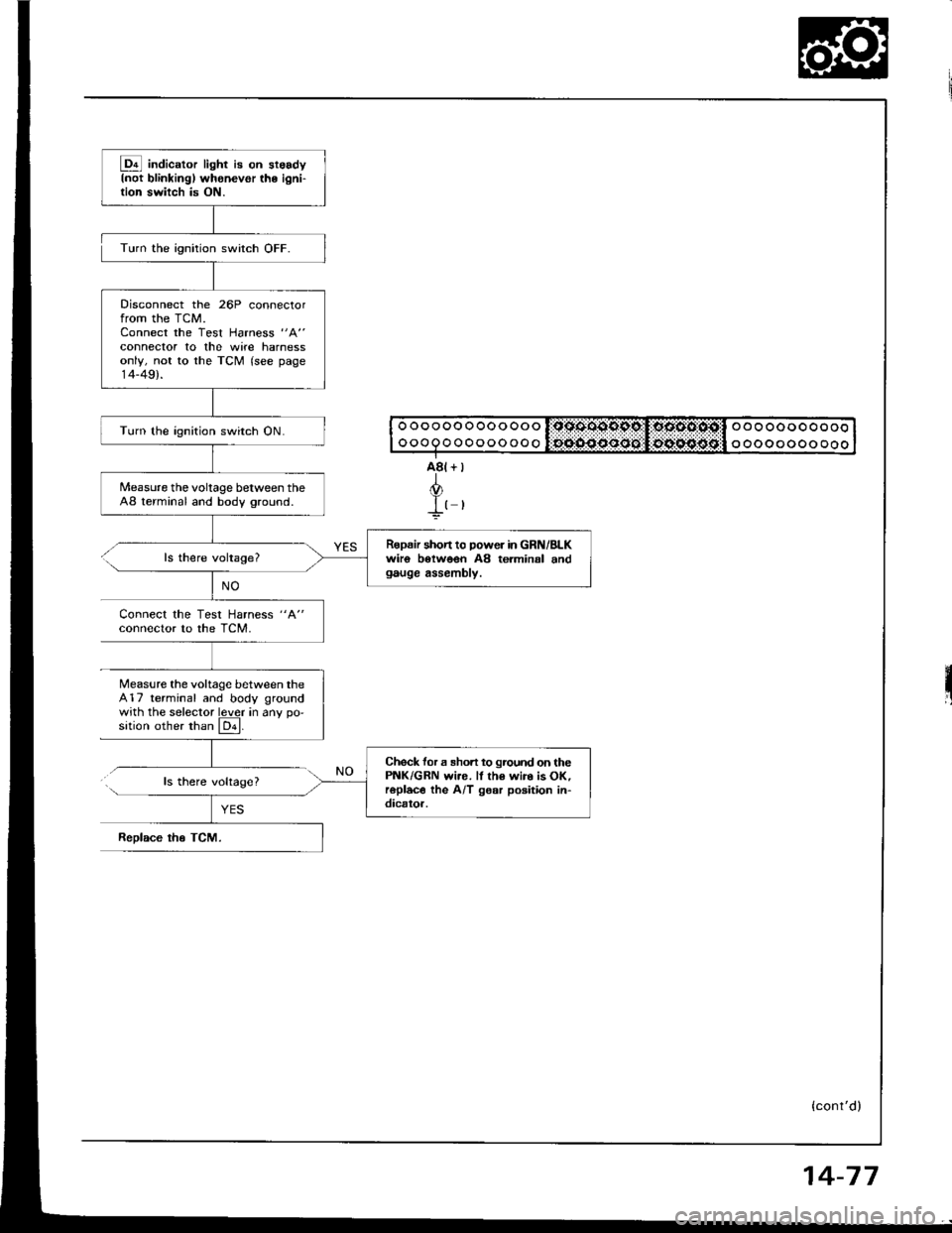
@ indic"to, light i8 on st6sdyInot blinkingl whenevor the ioni-tion switch is ON.
Disconnect the 26P connectorfrom the TCM.Connect the Test Harness "A"
connector to the wite harnessonly, not to the TCM (see page14-49).
Turn the ignition switch ON.
Measure the voltage between theA8 terminal and body ground.
Ropair shon to power in GRN/BLKwiro botwoen A8 terminal andgauge assembly.
Check for a sho.t to ground on thePNK/GRN wi.e. ll th€ wir. is OK,roplac€ the A/T gear poaition in-dicator.
Turn the ignition switch OFF.
ls there voltage?
Connect the Test Harness "A"
conneclor to the TCM.
Measure the voltage between the417 terminal and body groundwith the selector lever in anv oo'sition other than El.
ls there volrage?
ReDlace tho TCM.
o o o o oo o oo o oo o l:qssoo9pc,I:oocto:osil o o o oo o o o o oooooQoooooooooo oo o oooo ooo
{cont'd)
14-77
Page 470 of 1413
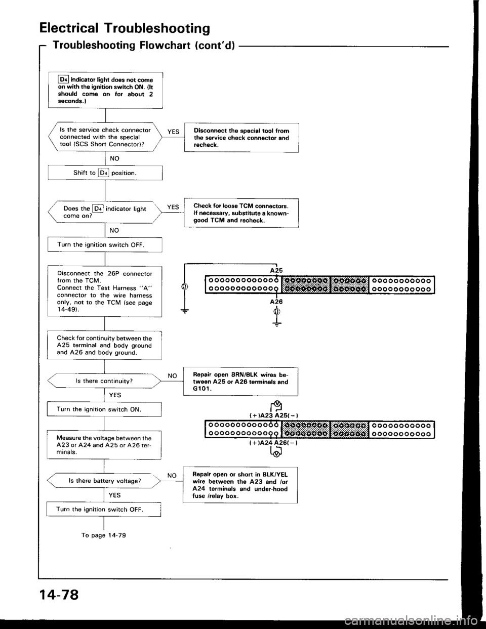
Electrical Troubleshooting
Troubleshooting Flowchaft (cont'dl
Does the @ indicatorcome on?
ls there baftery voltage?
YES
lighr
I A25
| | o ooooo o oo o ooo r:sjc.o.sl'1*st,li*os.s.4tcl ooo oo oooooo I
I I o o o o o o o o o o o o q lifrif.S..n${5git:li$gg-:aiiigitll o o o o o o o o o o o I|--.-T..-I a26
+d
+
I + )A23 A25l - l
(+ tA24 426(- |t\@
Lq4 indicator light do6s not comeon with the ignition switch ON. (ltshould come on Ior about 2seconds.l
ls the service check connectorconnected with the specialtool ISCS Short Connectod?
Diaconnect tho spocial tool fromth6 sgrvice check connoctor andrecheck.
Check {or loos6 TCM connoctors.lf necessaw, substitute a known-good TCM and recheck.
Turn the ignition switch OFF.
Disconnect the 26P connectorfrom the TCM.Connect the Test Harness "A"
conneclor to the wile harnessonly, not to the TCM (see page14-49).
Check for continuity between theA25 terminal and body groundand A26 and body ground.
R€pair open BRN/BLK wires be-twe6n A25 or A26 torminals andG 101.
Turn the ignition switch ON.
Measure the voltage between theA23 or A24 and A25 or A26 termrnals-
Repaii open or short in BLK/YELwire between tho A23 and /ot424 terminals and underhoodtuse /relav box.
Turn the ignition switch OFF.
To page 14-79
14-78
Page 474 of 1413
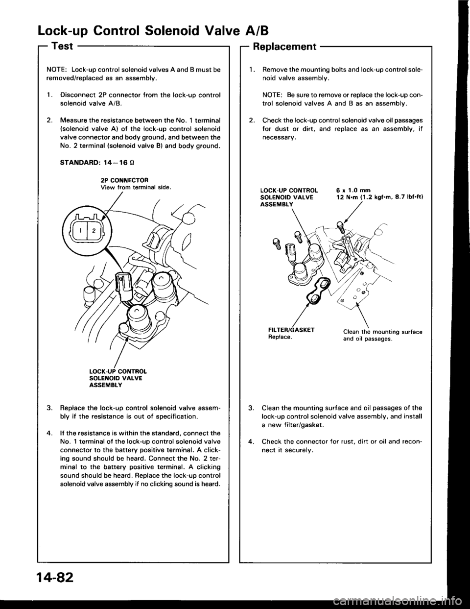
Lock-up Control Solenoid Valve A/B
NOTE: Lock-uD control solenoid valves A and B must be
removed/replaced as an assemblv.
l. Disconnect 2P connector trom the lock-uo control
solenoid valve A/8.
2. Measure the resistance between the No. 1 terminal(solenoid valve A) ot the lock-up cont.ol solenoid
valve connector and body ground, and between the
No. 2 terminal (solenoid valve B) and body ground.
STANDARD: 14- 16 O
2P CONI{ECTORView trom terminal side.
SoLENOTO VAI-VEASSEMBLY
Reolace the lock-uo control solenoid valve assem-
bly if the resistance is out of specitication.
lf the .esistance is within the standard, connect the
No. 1 terminal ot the lock-uo control solenoid valve
connector to the battery positive terminal. A click-
ing sound should be heard. Connect the No. 2 ter-
minal to the battery positive terminsl. A clicking
sound should be heard. Replace the lock-up control
solenoid valve assembly if no clicking sound is heard.
?
4.
Replacement
Remove the mounting bolts and lock-up control sole-
noid valve assembly.
NOTE: Be sure to remove or replace the lock-up con-
trol solenoid valves A and B as an assembly.
Check the lock-up control solenoid valve oil passages
tor dust or dirt. and replace as an assembly, if
neceSsary.
6 x 1.0 mm12 N.m (1.2 kgf.m,8.7 lbf'ft)
Clean the mounting sudaceand oil passages.
Clean the mounting surtace and oil passages of the
lock-up control solenoid valve assembly. and install
a new filter/gasket.
Check the connector for rust, dirt or oil and recon-
nect rt securely.
14-82