HONDA INTEGRA 1994 4.G Workshop Manual
Manufacturer: HONDA, Model Year: 1994, Model line: INTEGRA, Model: HONDA INTEGRA 1994 4.GPages: 1413, PDF Size: 37.94 MB
Page 471 of 1413
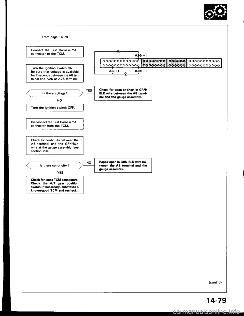
Connect the Test Harness "A"
connector to the TCM.
Turn the ignition switch ON.8e sure that voltage is availablefor 2 seconds between thg A8 tor-minal and A25 or A26 terminal.
Chrck for opon or rhort in GR /8LK wirc bctw.on th. A8 termi-nal and tha gauOa arrambly.
Turn the ignition switch OFF.
Disconnect the Test Harness "A"
connector from the TCM.
Check for continuity between theA8 terminal and the GRN/BLKwire at tho gaugo assgmbly (see
section 23).
B.p.ir op.n in GRI{/BLK wi.. bo-lwaen the A8 terminal and th.gauga 6aaombly.
Ch€ck for loor6 TCM conn6ctor3.Check the A/T goa. polition
awitch. ll noc€$ary, subrtitutg aknown-good TCM .nd rochock.
ooooooooooo
ooooooooooo
oooooooooooo
oooooooooooo
a26t - |
A8(+)
(cont'd)
14-79
Page 472 of 1413
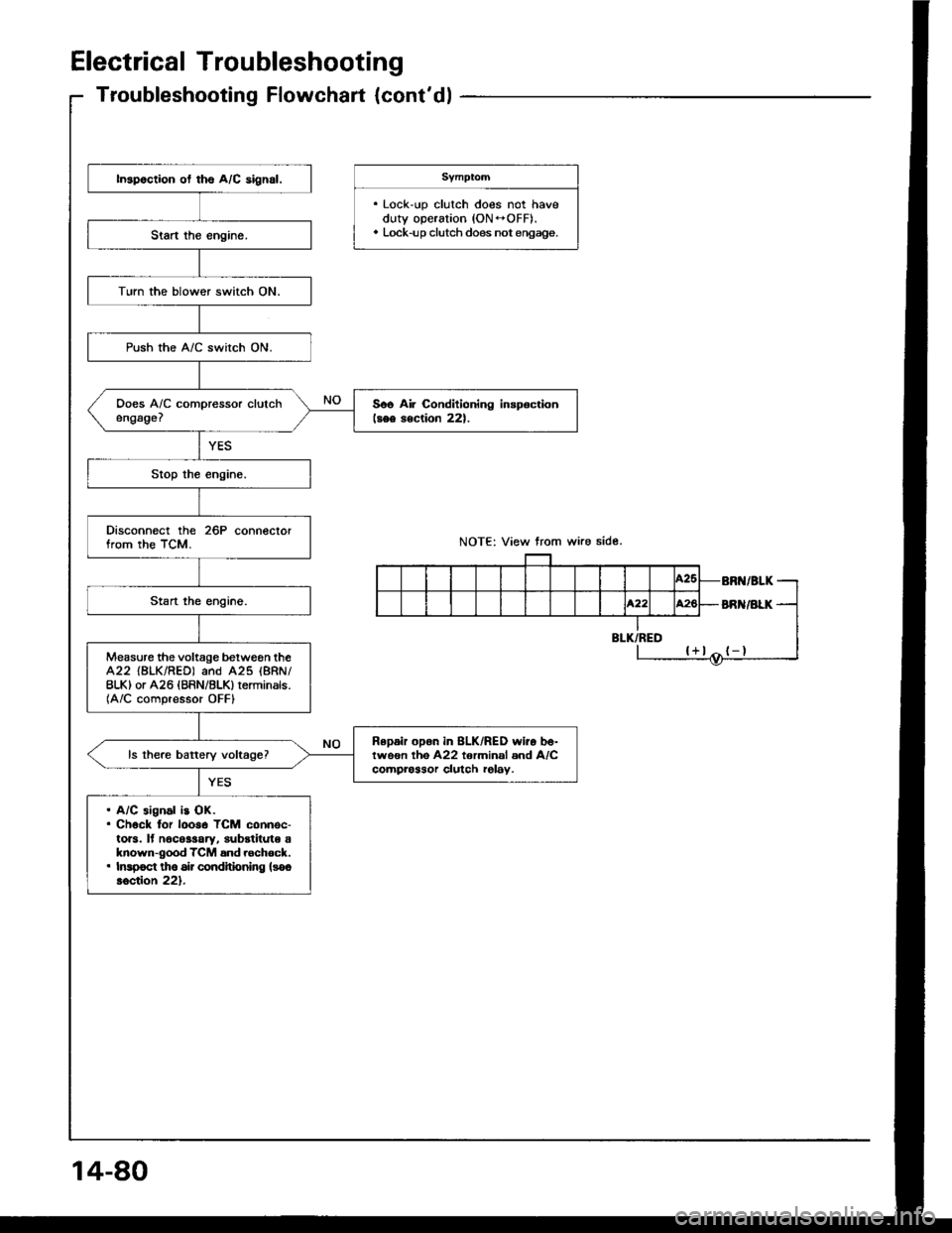
Electrical Troubleshooting
Troubleshooting Flowchart {cont'dl
. Lock-up clutch does not haveduty operation (ON -OFF).. Lock-up clutch does not engage.
In3poction ol ths A/C aign6l.
TLrrn the blower switch ON.
Push the A/C switch ON.
Soe Air Condilioning inspoctionlsee rection 221.
Disconnect the 26P conneclorfrom the TCM.
Measure the voltage between theA22 {BLK/RED) and A25 (8RN/
BLKI or A26 IBRN/BLK) terminals.(A/C compressor OFFI
Repair opon in 8LK/RED wiio b6-twoon lho A22 torminal and A/Ccomprossor clulch rel6y.
. A/C aignal ls OK.. Chock lor looso TCM connec-toB. lf n6co$ary, substitute aknown-good TCM and rschock.. Inrpoct tho 6ir condhioning lsooloction 221.
BR /ALK
Page 473 of 1413
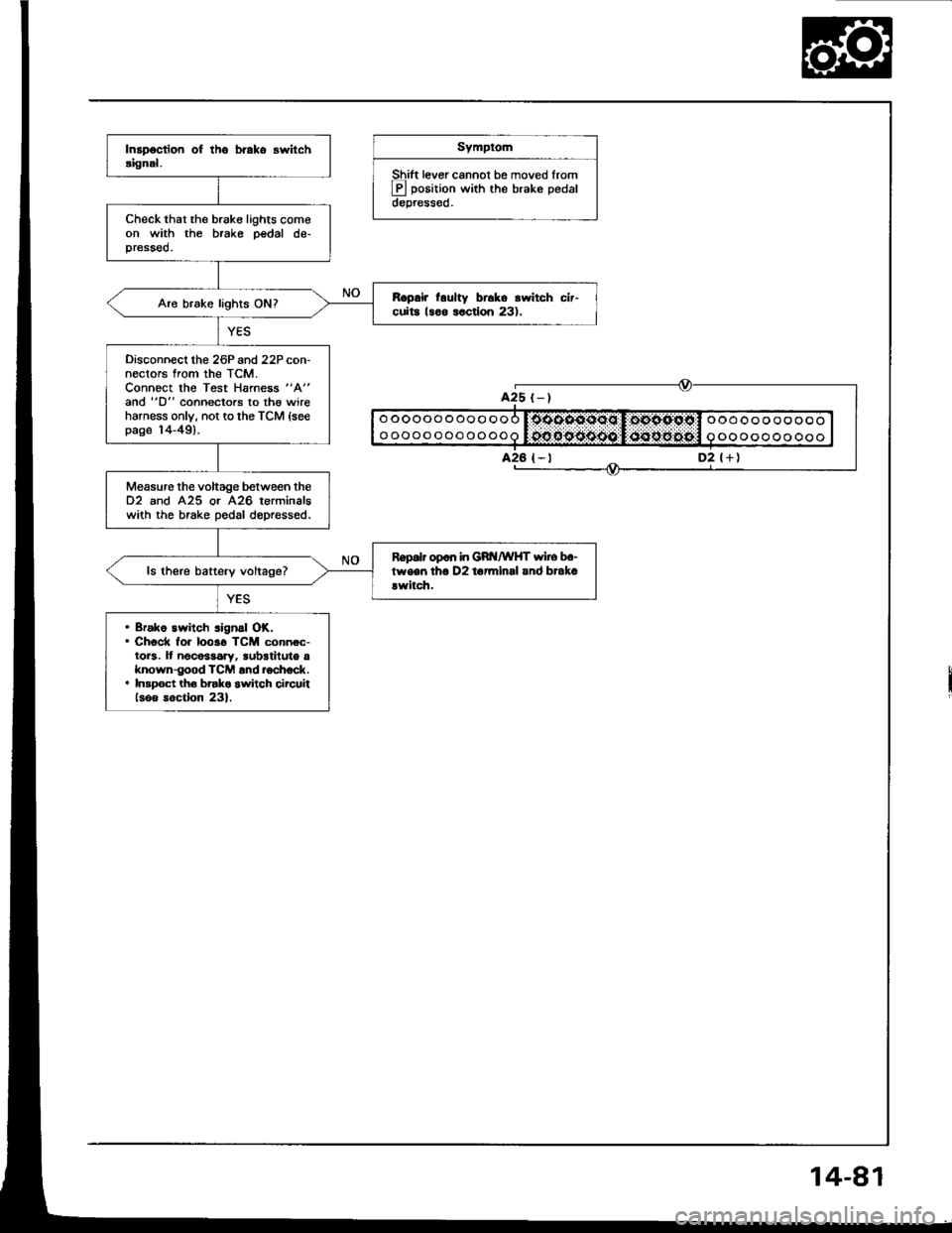
Symptom
Shift lever cannot be moved lrom
E position with the brake pedaldepressed.
Check thar the brake lights comeon with the brake pedal de-pressed.
R.prir l.ulty br6ko rwitch cir-cuita 18o6 lactlon 231.Aro brake lights ON?
Disconnecl lhe 26P and 22P con-nectors from the TCM.Connoct the Test Harness "A"
and "D" coonectors to th€ wireharness only, not to the TCM {seepage 14-49).
Measure the voltage between the02 and 425 or A26 terminalswith the brake pedal dopressed.
Ropalr op6n in GRt{/wHT wiro b.-tween tho D2 to7minsl and brak.!witch.ls there battery voltage?
. Bfako switch signal OK.. Check for 10036 TCM connec-tors. It noco$ary, sub3tiluto aknown-good TCM and ioch6ck.. Insp6ct tho brako switch circuiilsoo soction 23).
oooooooooooo
oooooooooooo
ooooooooooo
oooooooooo
A25 t-)
D2 l+)
Page 474 of 1413
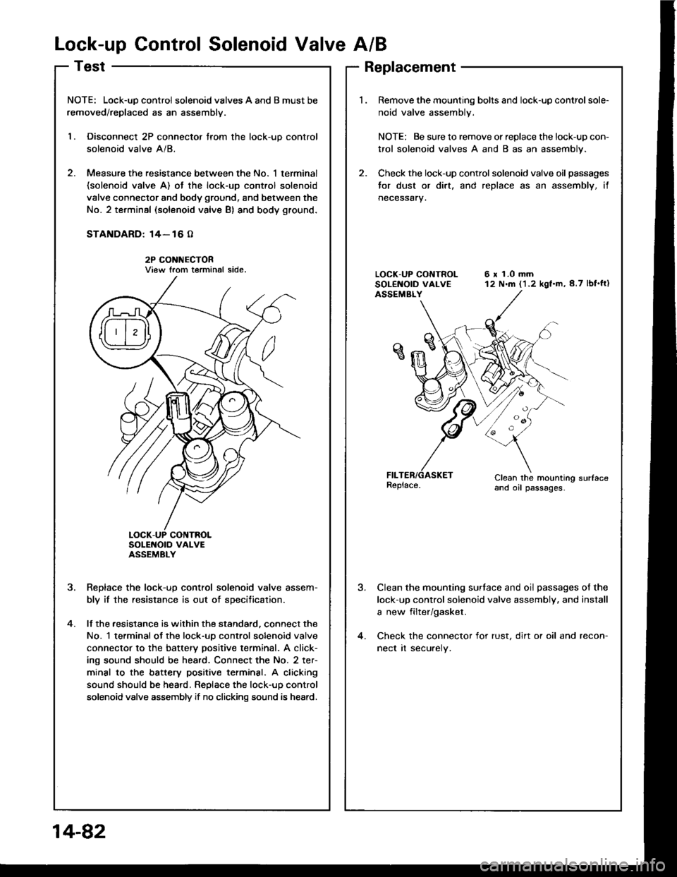
Lock-up Control Solenoid Valve A/B
NOTE: Lock-uD control solenoid valves A and B must be
removed/replaced as an assemblv.
l. Disconnect 2P connector trom the lock-uo control
solenoid valve A/8.
2. Measure the resistance between the No. 1 terminal(solenoid valve A) ot the lock-up cont.ol solenoid
valve connector and body ground, and between the
No. 2 terminal (solenoid valve B) and body ground.
STANDARD: 14- 16 O
2P CONI{ECTORView trom terminal side.
SoLENOTO VAI-VEASSEMBLY
Reolace the lock-uo control solenoid valve assem-
bly if the resistance is out of specitication.
lf the .esistance is within the standard, connect the
No. 1 terminal ot the lock-uo control solenoid valve
connector to the battery positive terminal. A click-
ing sound should be heard. Connect the No. 2 ter-
minal to the battery positive terminsl. A clicking
sound should be heard. Replace the lock-up control
solenoid valve assembly if no clicking sound is heard.
?
4.
Replacement
Remove the mounting bolts and lock-up control sole-
noid valve assembly.
NOTE: Be sure to remove or replace the lock-up con-
trol solenoid valves A and B as an assembly.
Check the lock-up control solenoid valve oil passages
tor dust or dirt. and replace as an assembly, if
neceSsary.
6 x 1.0 mm12 N.m (1.2 kgf.m,8.7 lbf'ft)
Clean the mounting sudaceand oil passages.
Clean the mounting surtace and oil passages of the
lock-up control solenoid valve assembly. and install
a new filter/gasket.
Check the connector for rust, dirt or oil and recon-
nect rt securely.
14-82
Page 475 of 1413
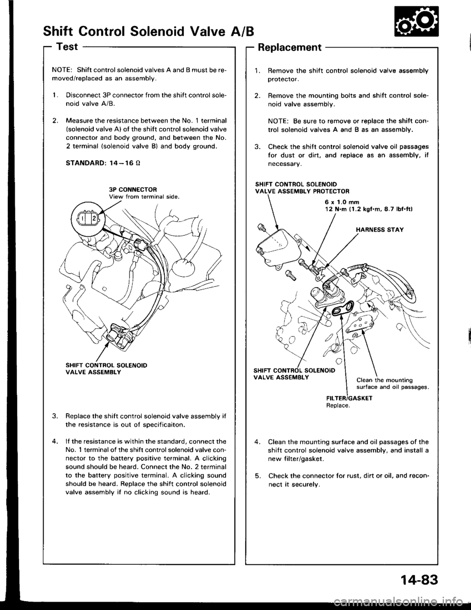
Shift Control Solenoid ValveA/B
Test
NOTE: Shift controlsolenoid valves A and B must be re-
moved/replaced as an assembly.
1.Disconnect 3P connector from the shitt control sole-
noid valve A/8.
Measure the resistance between the No. 1 terminal(solenoid valve A) of the shift control solenoid valve
connecto. and body ground, and between the No.
2 terminal (solenoid valve B) and body ground.
STANDARD: 14- 16 O
SHIFT CONTROL SOLENOIOVALVE ASSEMBLY
Replace the shift control solenoid valve assembly if
the resistance is out oI sDecificaiton.
lf the resistance is within the standard, connect the
No. 1 terminalof the shift controlsolenoid valve con-
nector to the battery positive terminal. A clicking
sound should be heard. Connect the No. 2 terminal
to the battery positive terminal. A clicking sound
should be heard. Replace the shift control solenoid
valve assembly if no clicking sound is heard.
3.
1.Remove the shift control solenoid vaive assembly
protector.
Remove the mounting bolts and shift control sole-
noid valve assembly.
NOTE: Be sure to remove or replace the shitt con-
trol solenoid valves A and B as an assembly.
Check the shitt control solenoid valve oil passages
for dust or dirt, and replace as an assembly, it
necessary.
Clean the mounting surface and oil passages of the
shitt control solenoid valve assembly, and install a
new filter/gasket.
Check the connector for rust, dirt or oil, and recon-
nect it securely.
6 x 1.0 mm12 N'm (1.2 kgl.m,4.7 lbl.ftl
VALVE ASS€MBLYClean the mountingsurface and oil passages.
Replace.
14-83
Page 476 of 1413
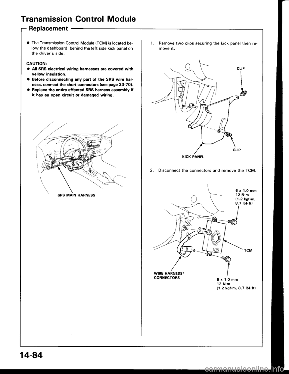
Transmission Control Module
Replacement
I The Transmission Control Module (TCMI is located be-
low the dashboard, behind the lelt side kick panel on
the driver's side.
CAUTION:
a All SRS electrical wiring hahesses are covered withyellow insulation.
a Betore disconnecting any pan ot the SRS wile har-
ness. connect the short connectors lsee page 23-7O).
a Replace the entir6 affected SRS harness ass€mbly if
it has an open circuit or damaged wiring.
1. Remove two clips securing the kick panel then
move it.
2. Disconnect the connectors and remove the TCM.
6 x 1.0 mm12 N'm{1.2 kgf.m,8.7 tbf.Itl
WIRE HARNESS/CONNECTORS6 x 1.0 mm12 N.m(1.2 kgf.m, 8.7 lbt.ftl
KICK PANEL
SRS MAIN HARNESS
14-84
Page 477 of 1413
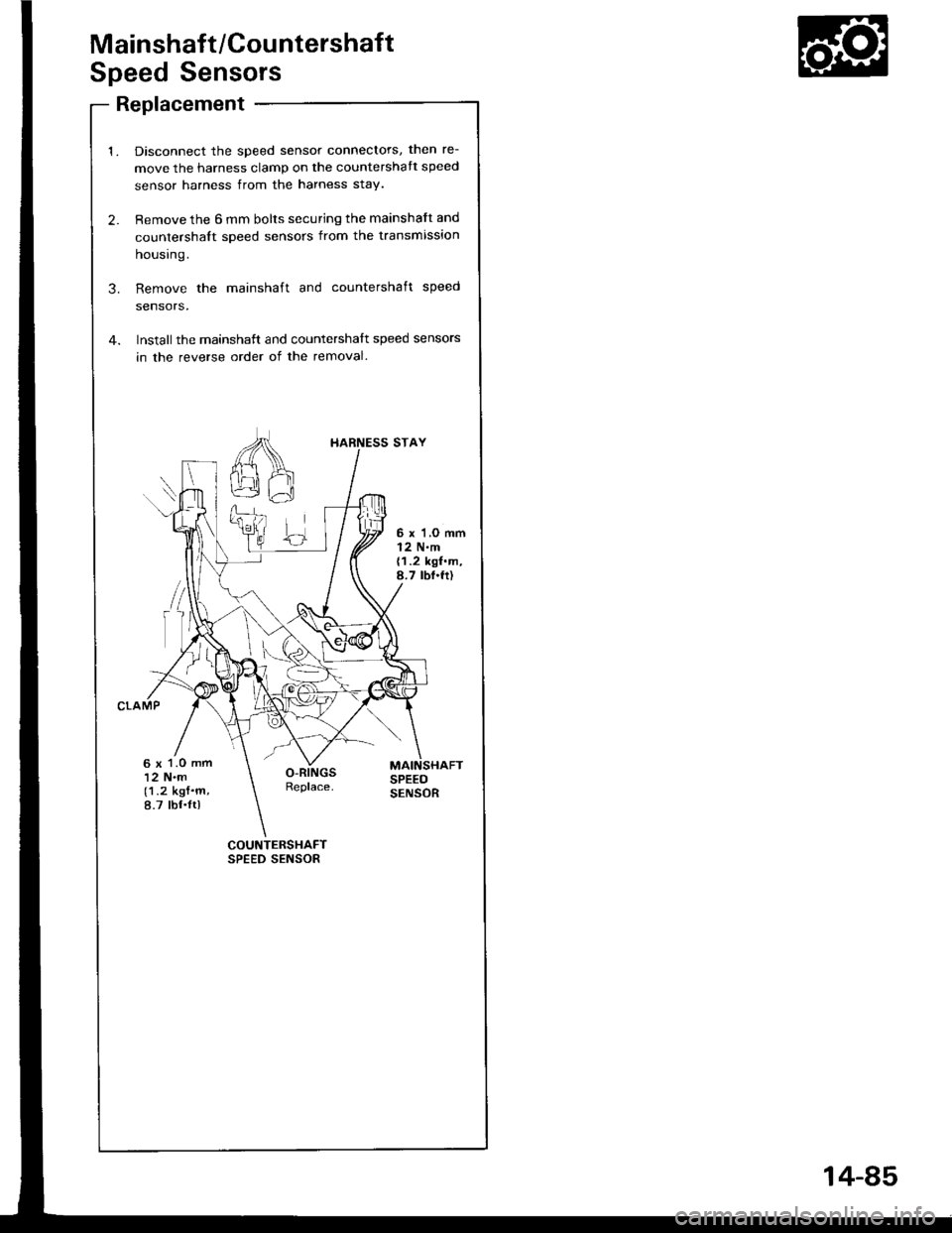
Mainshaft/Countershaft
Speed Sensors
Replacement
Disconnect the speed sensor connectors, then re-
move the harness clamp on the countershatt speed
sensor harness from the harness stay.
Remove the 6 mm bolts securing the mainshaft and
countershalt speed sensors from the transmission
housrng.
Remove the mainshaft and countershaft speed
sensors,
Installthe mainshatt and countershalt speed sensors
in the reverse order of the removal.
COUNTERSHAFTSPEED SENSOR
I{ARNESS STAY
6 x'l,O mml2 N.m{1.2 kgf.m,8.7 tbf.fr)
6 x 1.O mm12 N.m(1.2 kgf.m,8.7 tbf.ltl
14-85
Page 478 of 1413
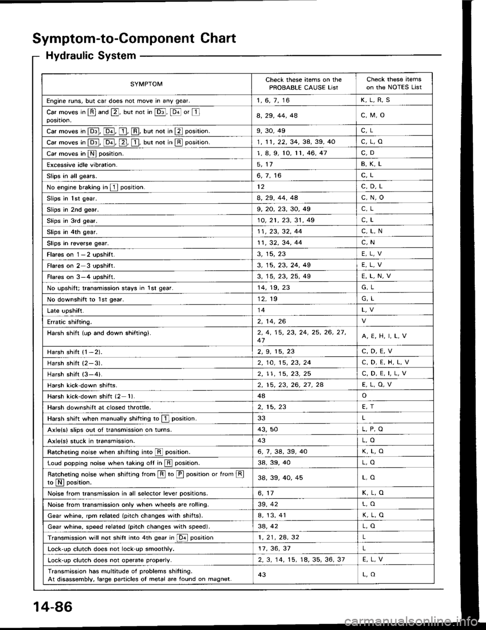
Symptom-to-Component Chart
Hydraulic System
SYMPTOMCheck these items on the
PROBABLE CAUSE ListCheck these items
on the NOTES List
Engine runs, but car does not move in any gear.1, 6, 7, 16K,L,R,S
Car moves in @ and @, but not in @, @ or Iposataon.a, 29, 44. 4ac,M,o
Car moves in E, @, [, @, uut not in E position.9,30,49C, L
car moves in p:1, [o-il, [2-], [!, uut not in E position.1, 11, 22, 34, 38, 39, 40c,L,o
Car moves in N position.1, 8, 9, 10, 11,46,47C,D
Excessive idle vibration.5, 1'1B,K,L
Slips in all gears.6, 7, 16C,L
No engine braking in E position.12C,D,L
Slips in 1st gear.8, 29, 44, 4Ac,N,o
Slips in 2nd gear.9, 20, 23, 30, 49C, L
Slips in 3rd gear.10, 21 , 23, 31 , 49C,L
Slips in 4th gear.11, 23, 32, 44C,L,N
Slips in reverse gear.11,32,34,44C,N
Flares on 1-2 upshilt.3, 15, 23E,L,V
Flareson2 3 upshilt.3, 15, 23, 24, 49E,L,V
Flares on 3-4 upshift.3, 15, 23, 25, 49E,L,N,V
No upshift; transmission stays in 1st gear.14,19,G, L
No downshift to lst gear.12. 19G, L
Late upshift.14
Erratic shitting.2, 14,26
Harsh shift (up and down shiftingl.2, 4, 15, 23, 24, 25, 26, 27,
47A,E, H, I, L,V
Harsh shitt {1-2).2, 9. 15, 23C,D,E,V
Harshshilt (2-3).2, 10, 15, 23, 24C,D,E,H,L,V
Harsh shift (3-4).2,| 1, 15, 23, 25C, D, E, I,L,V
Harsh kick'down shifts.2, 15, 23, 26, 27. 2AE,L,O,V
Harsh kick-down shift 12 1)48o
Harsh downshift at closed throttle.2, 15, 23FT
Harsh shift when manually shifting to E] position.33L
Axle{s} slips out of transmission on turns.43,50
Axlels) stuck in transmission.43L,O
Ratcheting noise when shifting inro E position.6,7,38,39,40K,L,O
Loud popping noise when taking ott in E position.3a,39,40L,O
Ratcheting noise when shifting from E to E position or from Eto N I oosition.38,33,40,45L,O
Noise from transmission in all selector lever positions.6, 11K,L,O
Noise trom transmission only when wheels are rolling.39, 42L,O
Gear whine, rpm related (pitch changes with shitts).a, 13, 41K,L,O
Gear whine, speed rel6ted (pitch changes with speed).38, 42L,O
Transmission will not shift into 4th gear in @ position1,21,24.32L
Lock-up clutch does not lock-up smoothly.17, 36, 37L
Lock-up clutch does not operate properlV.2.3. 14, 15. 18, 35, 36, 37E,L,V
Transmission has multitude of problems shitting.
At disassembly, large particles oI metal are found on magnet.43L,O
14-86
Page 479 of 1413
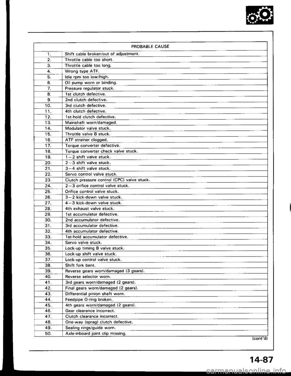
PROBABLE CAUSE
1Shitt cable broken/out of adiustment.
Throttle cable too short.
Throttle cable too long.
Wrong type ATF.
ldle rpm too low/high.
o.Oil pump worn or binding.
7.Pressure regulator stuck.
8.l st clutch detective.
9.2nd clutch detective.
10.3rd clutch defective.
114th clutch defective.
12.1 st'hold clutch defective.
13.Mainshatt worn/damaged.
14.Modulator valve stuck.
Throttle valve B stuck.
lo.ATF strainer clogged.
Toroue converter def ective.
18.Torque converter check valve stuck.'I 9.1-2 shift valve stuck.
2-3 shift valve stuck.
213-4 shift valve stuck.
Servo control valve stuck.
23.Clutch Dressure control (CPC) valve stuck.
2-3 orifice control valve stuck.
Orifice control valve stuck.
26.3-2 kick-down valve stuck.
27.4-3 kick-down valve stuck.
24.4th exhaust valve stuck.
29.1st accumulator detective.
30.2nd accumulator detective.
313rd accumulator defective.
4th accumulator defective.
1 st-hold accumulator defective.
Servo valve stuck.
35.Lock-up timing B valve stuck.
36.Lock-up shift valve stuck.
37.Lock-uo control valve stuck.
38.Shift fork benr.
39.Reverse gears worn/damaged (3 gears).
40.Reverse selectot worn.
413rd gears worn/damaged (2 gears).
Final qears worn/damaged (2 gearsl.
43.Differential Dinion shatt worn.
44.Feedpipe O-ring broken.
45.4th qears worn/damaged (2 gearsl
Gear clearance incorrect.
47.Clutch clearance incorrect.
48.One-way (sprag) clutch defective.
49.Sealinq rings/quide worn.
50.Axle-inboard joint clip missing.
Page 480 of 1413
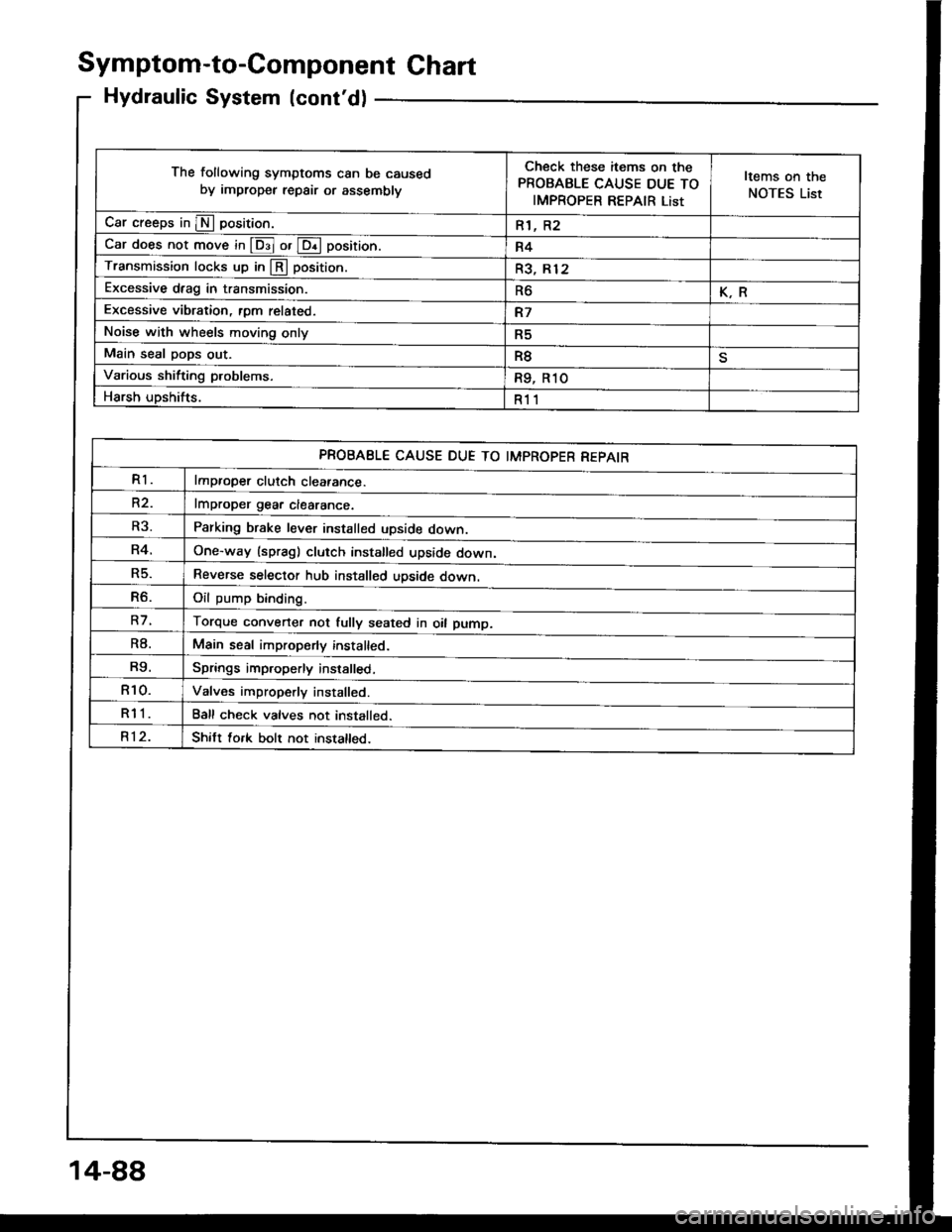
Symptom-to-Component Ghart
Hydraulic System (cont'd)
The following symptoms can be caused
by improper repair or assemblv
Check these items on the
PROBABLE CAUSE DUE TO
IMPROPER REPAIR List
Items on the
NOTES List
Car creeps in E position.R1, R2
Car does not move in @ or @ position.R4
Transmission locks up in @ position.R3, Rl2
Excessive drag in transmission.R6K.R
Excessive vibration, rom related.R7
Noise with wheels moving onlyR5
Main seal pops out.R8
Various shifting problems.R9, R1O
Harsh upshifts.R11
PROBABLE CAUSE DUE TO IMPROPER REPAIR
R1lmproper clutch cleatance.
R2.lmDroDer qear clearance.
Parking brake lever installed upside down.
One-way (spragl clutch installed upside down,
Reverse selector hub installed upside down.
Oil oumo bindind
Torque converter not fully seated in oil pump.
Main seal improperly installed.
Springs improperly installed,
Valves improperly installed.
Ball check valves not installed.
Shitt fork bolt not installed.
R3.
R4.
R5.
R6.
R7.
R8.
R9.
R10.
R11
R12.
14-88