Page 98 HONDA INTEGRA 1994 4.G Repair Manual
[x] Cancel search | Manufacturer: HONDA, Model Year: 1994, Model line: INTEGRA, Model: HONDA INTEGRA 1994 4.GPages: 1413, PDF Size: 37.94 MB
Page 144 of 1413
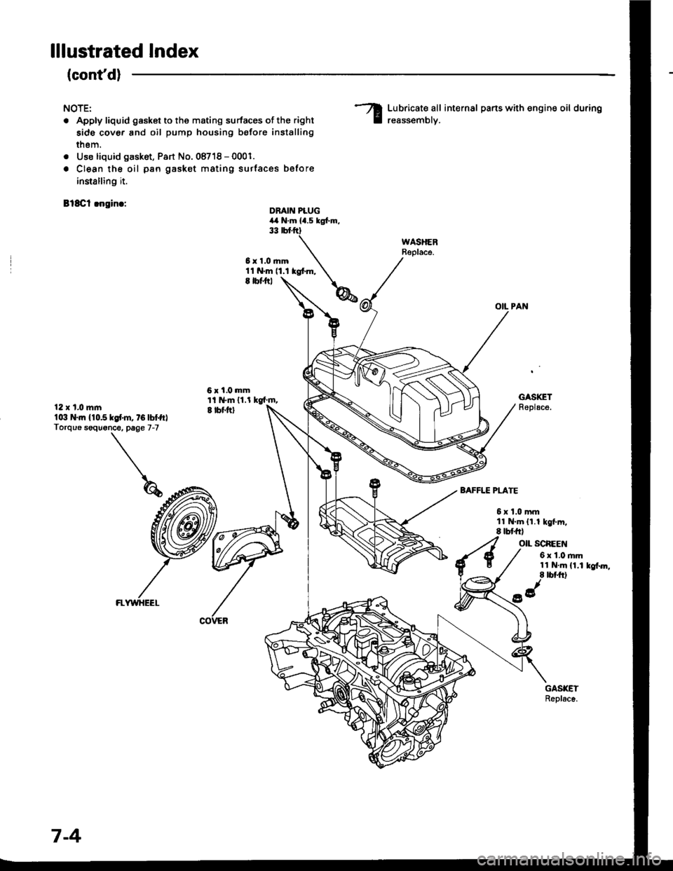
lllustrated Index
(cont'd)
NOTE:
. Apply liquid gasket to the mating surfaces of the right
side cover and oil pump housing before installing
thsm.
. Use liquid gask6t, Part No. 08718 - 0001.
. Clean the oil pan gasket mating surtac€s before
innalling it.
Bl8Cl !ngin.:
Lubricate all internal parts with engine oil during
reassemblv.
OIL PAN
DBAIN PLUG4,a N.m la.s tgl.m.33 rbr.ftt
6x1.0mm11 N.m (1.1 kgt m,E |bfitl
6x1.0mmti l*m 11.l kgf m,I tbf.ftl
GASKETReplace.12 x t.0 mlnlo:t N.|n 110.510f'm, tG lbffrlTorque soquonce. page 7-7
BAFFLE PLATE
6xl.0mmll N.m (1.1 kgt m.8 tbt frl
O|L SCAEEN
6 x 1.0 rim11 N.m (1.1 kgf.m,8 tbt ft)
FLWYHEEL
7-4
Page 145 of 1413
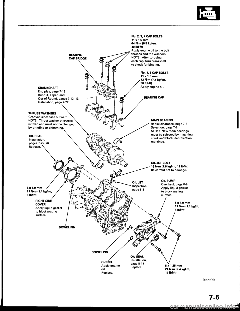
BEARINGCAP BRIDGE
No. a 3, /a CAP BOLTSll x 1.5 mm64 N.m {6.5 kgt m,49 tbf.ftlApply engine oilto tho boltthreads and the washers.NOTE: Aftertorquingeach cap, turn crankshaftto check for binding.
No. 1,5 CAP BOI-TS11 x 1.5 mm73 N.m {7.4 kgf.m,56 tbt'ft|Apply engine oil.
BEARING CAP
CRANKSHAFTEnd play, page 7-12Runout, Taper, andOut-of-Round, pages 7'12. 13Installation, page 7-22
YHRUST WASHERSGrooved sides lace outward.NOTE: Thrust washer thicknessis fixed and must not be chano€d
MAIN BEARINGRadial clearance. page 7 8S6l€ction, page 7-8NOTE: New main bearingsmust be selected by matchingcrank and block identificationmarxrngs.
OIL JEI BOLY16 N.m 11.6 kg{'m, 12lbtftlBe caretul not to damage.
OIL PUMPOverhaul, page 8-9Apply liquid gasket
to block matingsurface.
OIL SEALInstallation,pages 7-25, 26
11 N.m 11.1 kgt m,8 lbf ftl
Replace.
6r1.0mm
OIL JETInspection,page 8-8
OIL SEALInstellelion,page 8-11Replace.
RIGHT SIDECOVERApply liquid gasketto block matingsurface.
6x1.0mm11 N.m {1.18 rbf.ftlkSf.ft,
DOWEL PIN
DOWEL PIN
O.RING.Apply engineorl.Replace.
8 x 1.25 mm24 N.m {2.4 kgt m,17 tbtft)
(cont'd)
7-5
Page 146 of 1413
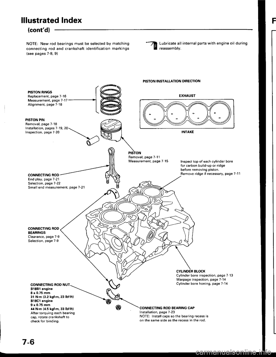
lllustrated IndexF
(cont'd)
NOTE: New rod bearings must be selected by
connecting rod and crankshaft identification
(see pages 7-8,9)
matching
marKrngs
Lubricate all internal parts with engine oil during
reassemorv.
PISTON RINGSReplacement, page 7'16Measurement. page 7-17Alignment, page 7 18
PISTON PINRemoval, page 7-18lnstallation, pages 7 19, 20Inspection, page 7'20
PISTON INSTALLATION DIRECTION
EXHAUST
INTAKE
Removal, page 7'11Measurement, page 7 15Inspect top of each cylinder borefor carbon build-up or ridgobetore removing piston.Remove ridge it necessary, page 7'11CONNECTING ROOEnd play, page 7-21
CONNECTING RODEEARINGSClearance, page 7-9Selection, page 7-9
CONNECTING ROD NUT818B1 ongine8x 0.75 mm31 N.m {3.2 kgf.m,23 lbf ftl818C1 engine9 x 0.75 mma,a N.m (4.5 kgt m, 33 lbf.ft|After torquing each bearangcap, rotate crankshaft tocheck for binding.
r-(,
Selection, page 7-22Small end measurement. page 7-21
BLOCXCylinder bore inspection, page 7 13Warpage inspection, page 7'14Cylinder bore honing, page 7-14
CONNECTING ROD BEARING CAPInstallation, page 7'23NOTE: Install caps so the bearing recess ison the same side as the recess in the rod.
r@
-1@
Page 151 of 1413
7.
8.
11.
9.
10.
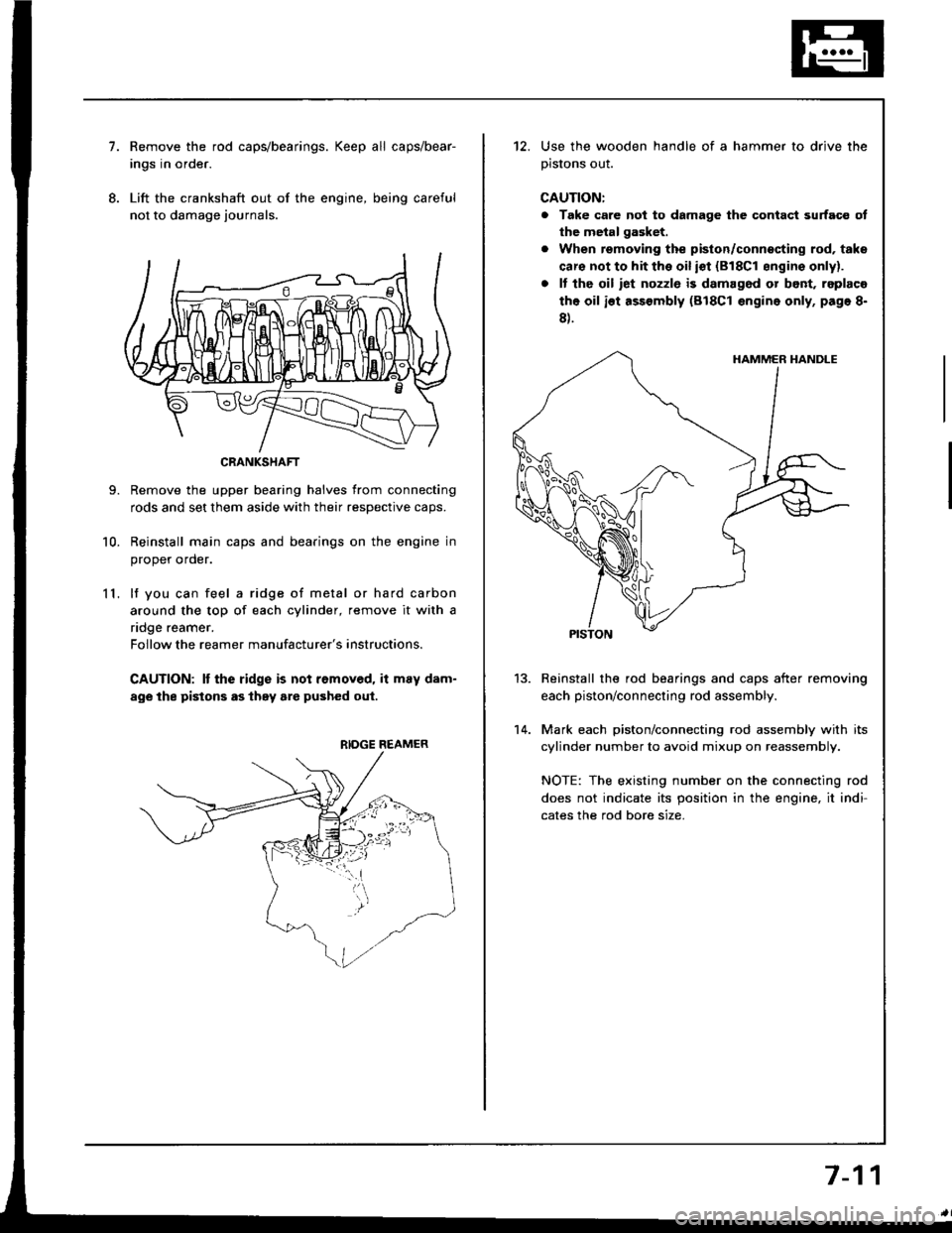
Remove the rod caps/bearings. Keep all caps/bear-
ings in order.
Lift the crankshaft out of the engine, being careful
not to damage journals.
Remove the upper bearing halves from connecting
rods and set them aside with their resDective caDs.
Reinstall main caps and bearings on the engine in
oroDer order.
lf you can feel a ridge of metal or hard carbon
around the top of each cylinder, remove it with a
ndge reamer.
Follow the reamer manufacturer's instructions.
CAUTION: It the ridge is not removed, it may dam-
age the pistons as they are pushed oul.
CRANKSHAFT
RIDGE REAMER
12. Use the wooden handle of a hammer to drive the
prslons ouI.
CAUTION:
a Take care not to damage the contact surfaco ot
the metal gasket.
. When removing the piston/connecting rod, taks
caro not to hit the oil iot {818C1 sngins onlyl.
. It tho oil iet nozzlo is damag6d or bont, replaco
the oil ist assembly (818C1 engine only, page 8-
8).
Reinstall the rod bearings and caps after removing
each piston/connecting rod assembly.
Mark each piston/connecting rod assembly with its
cylinder number to avoid mixup on reassembly.
NOTE: The existing number on the connecting rod
does not indicate its position in the engine, it indi-
cates the rod bore size.
13.
14.
7-11
Page 153 of 1413
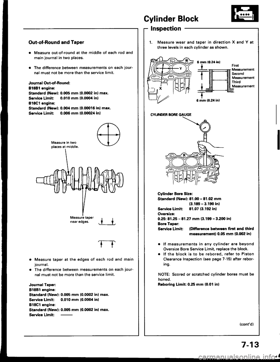
Out-ot-Round and Taper
. Measure out-of-round at the middle of each rod and
main journal in two places.
. The difference between msasurements on each jour-
nal must not be more than the se.vice limit.
Journal Oul-of-Round:
Bt8Bi.ngine:
Strndrrd (Now): 0.(x15 mm (0.0002 inl m!x.
Scrvicr Limit 0.010 mm (o.fixx inl
Bl8Cl cngins:
Strnd.rd {Nowl: 0.004 mm (0.(XD16 inl m!x.
Sorvicc Limit 0.qt6 mm {0.qx!2,1 in}
near edggs..t +
Measure taper at the edges of each rod and main
journal.
The difference between measurements on each jour-
nal must not be more than the service limit.
Journal Tapor:
8l8Bl angino:
Standard (Newl: 0.q)5 mm l0.0(Xl2 inl m.x.
Sorvico Limit 0.010 mm (0.0004 inl
BlSCl ongino:
Standrrd (Now): 0.005 mm (0.0002 inl m8x.
Scrvic€ Limit
frrgtMeaauremonlSecondMoa6urgmontThi.dM063uremgnt
G mm {0.24 in}
CYUNDER BORE GAUGE
Cyllndor Borr Siz.:
Standard (Ncwl: 81.q!- 81.02 mm(3.18, - 3.190 inl
Scrvicr Limh: 81.07 (3.192 in)
Ovar3izc:
O.25t 81.25 - 81.27 mm (3.199 - 3.200 inl
Borc Tlpor:
Scrvice Limit (Ditfcrcncc bctw!.n firtt tnd third
moasurcm.ntl 0.115 mm (0.002 in)
. lf moasur€ments in any cylindsr are beyond
Oversize Bore Service Limit, rsglace the block.
. lf the block is to be rebored, refer to Piston
Clearance Inspection (see page 7-151 after rebor-
ing.
NOTE: Scored or scratched cylinder bores must be
honed.
Rcboring Limil: 0.25 mm (0.01 inl
(cont'd)
Gylinder Block
Inspection
1. Measure wear and taDer in dirsction X and Y at
three levels in each cvlindsr as shown.
6mm
Y
7-13
Page 154 of 1413
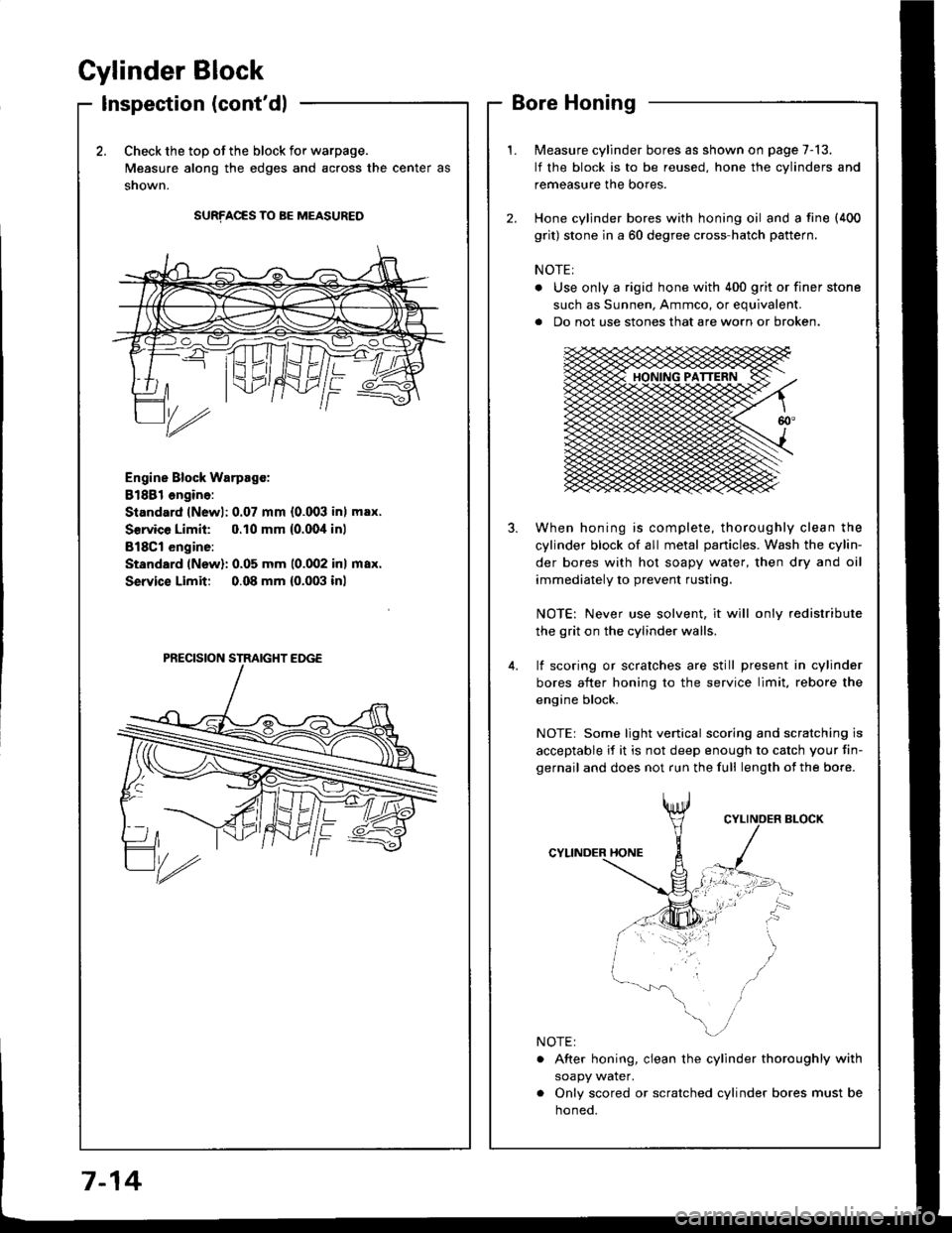
Cylinder Block
Inspection (cont'dl
2.Check the top of the block for warpage.
Measure along the edges and across the center as
snown.
SURFACES TO BE MEASURED
Engine Block Warpsgc:
81881 ongine:
Standard lNewl: 0.07 mm {0.003 inl max.
Service Limil: 0.10 mm {0.00,1inl
B18Cl engine:
Standard (New): 0.05 mm 10.002 inl max.
Service Limit 0.08 mm {0.003 inl
Measure cylinder bores as shown on page 7-13.
lf the block is to be reused, hone the cylinders and
remeasure the bores.
Hone cylinder bores with honing oil and a fine (400
grit) stone in a 60 degree cross-hatch pattern.
NOTE:
. Use only a rigid hone with 400 grit or finer stone
such as Sunnen, Ammco, or equivalent.
a Do not use stones that are worn or broken.
When honing is complete, thoroughly clean the
cylinder block of all metal panicles. Wash the cylin-
der bores with hot soapy water, then dry and oil
immediately to prevent rusting.
NOTE: Never use solvent, it will only redistribute
the grit on the cylinder walls.
lf scoring or scralches are still present in cylinder
bores after honing to the service limit, rebore the
engine block.
NOTEr Some light venical scoring and scratching is
acceptable if it is not deep enough to catch your fin-
gernail and does not run the full length of the bore.
CYLINDER HONE
. After honing, clean the cylinder thoroughly with
soapy water.
. Only scored or scratched cylinder bores must be
noneo.
7-14
Page 155 of 1413
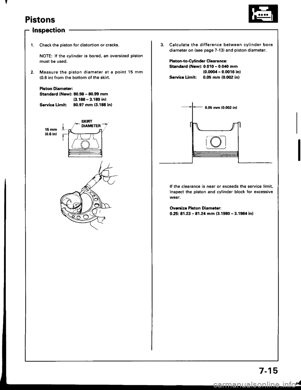
Pistons
Inspection
1. Check the oiston for distortion or cracks.3, Calculate the difference betw€on cvlinder bore
diameter on (see page 7-13) and piston diametsr.
Pbton-io"Cy'indor Clea18nco:
Stsndard (Nrwl: 0.010 - 0.0/O mm
{o.ofira - 0.0016 in}
S.rvic. Limit: 0.05 mm {0.002 in)
NOTE: lf the cylinder is bored, an oversized piston
must be used,
2. Moasur€ the piston diameter at a point l5 mm
(0.6 in) from the bottom of the skin.
Pbion Diamat6r:
Standard lNowl: 80.S - 80.99 mm(3.188 - 3.189 inl
Sorvica Limit 80.97 mm (3.188 in)
lf the clearance is near or €xc€eds the service limit,
inspect the piston and cylinder block for excessive
wear.
Ov.rsizc Pilton Diamcter:
O.25t 81,23 - 81.21|rnm {3.1980 - 3.198'l in)
rKI
7-1
Page 156 of 1413
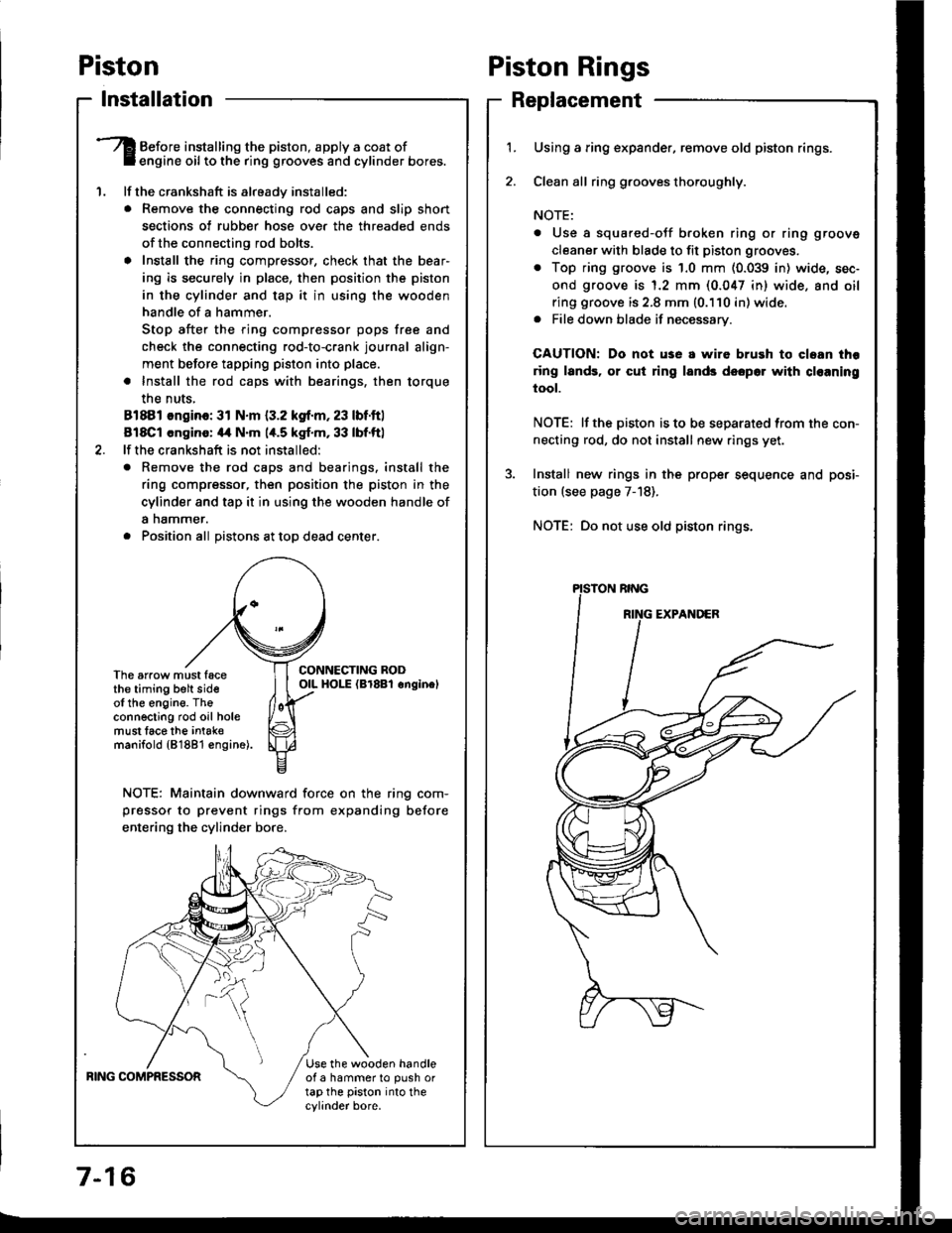
Piston
lnstallation
'1.
Before installing the piston, apply a coat ofengine oil to the ring grooves and cylinder bores.
lf the crankshaft is already installed:
. Remove the connecting rod caps and slip short
sections of rubber hose ove. the threaded ends
of the connecting rod bolts.
a Install the ring compressor, check that the bear'
ing is securely in place, then position the piston
in the cylinder and tap it in using the wooden
handle of a hammer.
Stop after the ring compressor pops free and
check the connecting rod-to-crank journal align-
ment before tapping piston into place.
. Install the rod caps with bearings, then torque
the nuts,
81881 ongino: 31 N.m {3.2 kgf.m, 23 lbf.ftl
818C1 cngino: 44 N'm 1,t.5 kgf.m, 33 lbf.ftl
lf the crankshaft is not installed:
o Remove the rod caps and bearings. install the
ring compressor, then position the piston in the
cylinder and tap it in using the wooden handle of
a nammer.
. Position all Distons at toD dead center.
CONNECTING RODOIL HOI-E (Br8Bl onginelThe arrow must facethe timing belt sideof the engine. Theconnecting rod oil holemust lace the intak€manifold {81881 €ngine).
NOTE: Maintain downward force on the ring com-
pressor to prevent rings from expanding before
entering the cylinder bore,
BING COMPRESSORUse the wooden handleof a hammer to push ortap the piston into thecylinder bore.
Piston Rings
Replacement
1.Using a ring expander, remove old piston rings.
Clean all ring g.ooves thoroughly.
NOTE:
. Use a squared-oJf broken ring or ring groove
cleaner with blade to fit piston grooves.
. Top ring groove is 1.0 mm (0.039 in) wide, sec-
ond groove is 1.2 mm (0.047 in) wide. and oil
ring groove is 2.8 mm (0.110 in) wide.. File down blade if necessary.
CAUTION: Do not use a wire brush to cloan thr
ring lands, or cut ring lands dsopo. with cl€aning
tool.
NOTE: lf the piston is to be separated from the con-
necting rod, do not install new rings yet.
Install new rings in the prope. sequence and posi-
tion (see page 7-18).
NOTE: Do not use old piston rings.
Page 157 of 1413
I
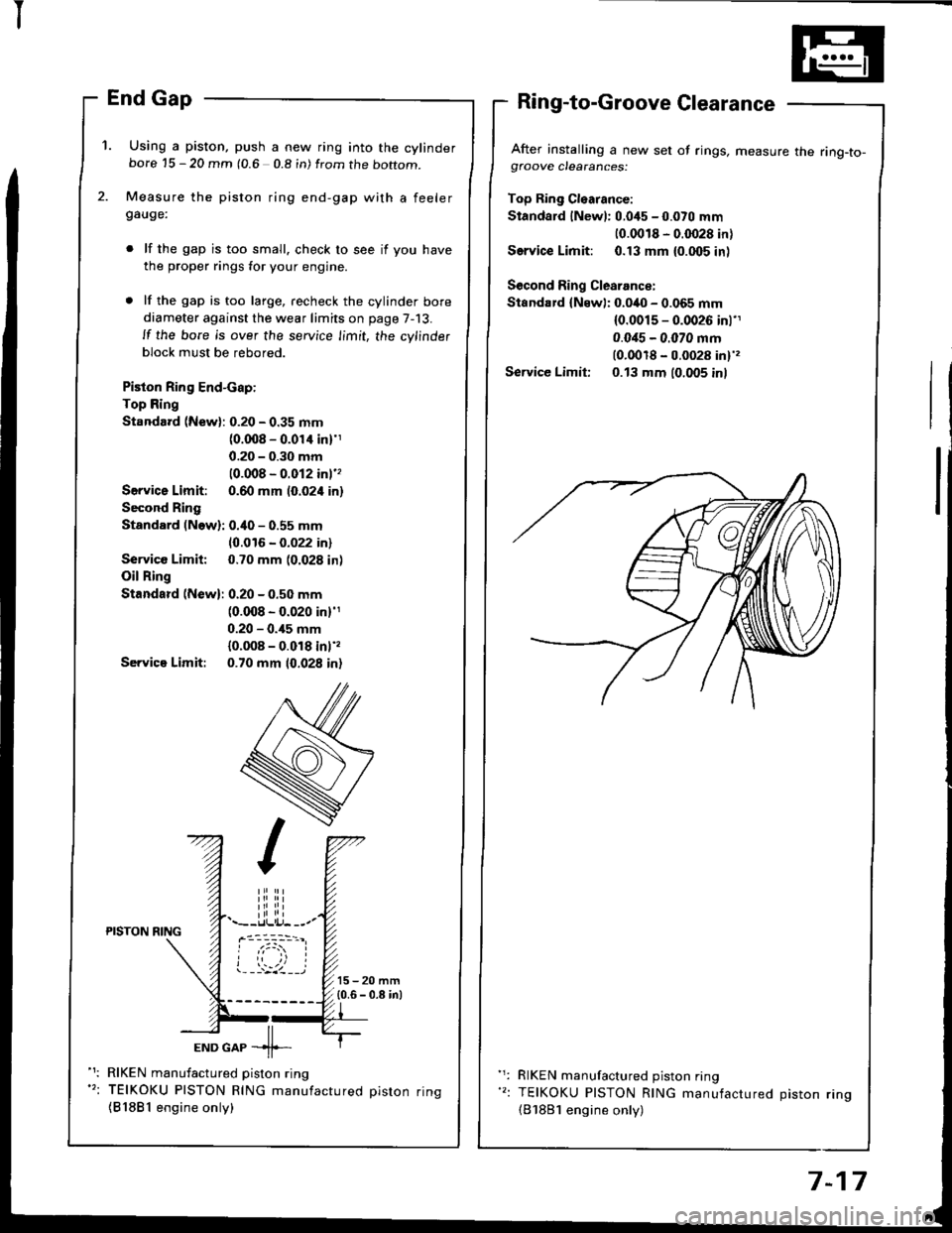
'1. Using a piston, push a new ring into the cylinderbore 15 - 20 mm (0.6 0.8 in) from the boftom.
Measure the piston ring end-gap with a feelergauge:
lf the gap is too small. check to see if you have
the proper rings for your engine.
lf the gap is too large, recheck the cylinder bore
diameter against the wear limits on page 7-13.
ll the bore is over the service limit, the cylinder
block must be rebored.
Piston Ring End-cap:
Top Ring
Standard (New): 0.20 - 0.35 mm(0.008 - 0.01'l inl'1
0.20 - 0.30 mm
10.008 - 0.012 inl''
Servica Limit: 0.60 mm (0.024 in)
Second Ring
Standard (Now): 0.40 - 0.55 mm
10.016 - 0.022 in)
Service Limit: 0.70 mm (0.028 in)
Oil Ring
Standard (New): 0.20 - 0.50 mm(0.008 - 0.020 in)'1
0.20 - 0.,15 mm
{0.008 - 0.018 inl',
Servica Limit: 0.70 mm 10.028 in)
After installing a new set of rings, measure the ring-to-gfoove clearances:
Top Ring Cl€arance:
Standard lNewl: 0.045 - 0.070 mm
10.0018 - 0.0028 in)
Service Limit: 0.13 mm {0.005 inl
Second Ring Clearance:
Standard {Newl: 0.040 - 0.065 mm(0.0015 - 0.0026 inl'1
0.0i15 - 0.070 mm(0.0018 - 0.0028 in)',
Service Limit: 0.13 mm (0.005 inl
iliiii.--r.llli.j- --.-PISTON NING
ioi
---'z llEND GAP -11--
RIKEN manufactured piston ring
TEIKOKU PISTON RING manufactured oiston rinq
{81881 engine only)
RIKEN manufactured piston ring
TEIKOKU PISTON RING manufactured Diston rino(B'1881 engine only)
7-17
Page 161 of 1413
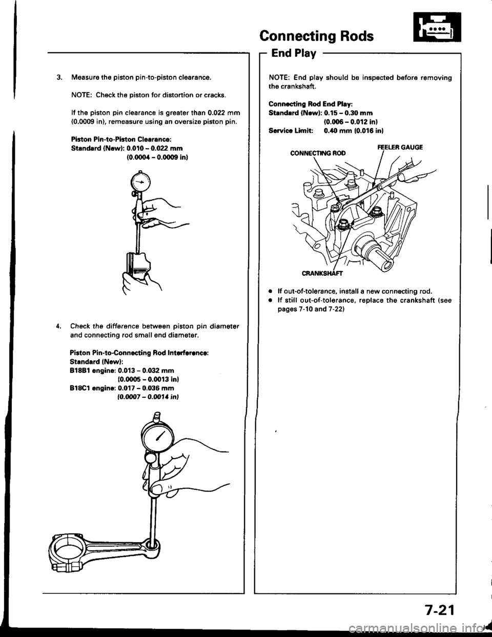
3. Measuro the piston pin-to-piston clearance.
NOTE: Check the Diston for distonion or cracks.
It the piston pin clearance is greater than 0.022 mm(0,0009 in), remeasure using an ovorsize piston pin.
Pbton Pin-to-PLton Cloeranco:
StlndErd (Ncwl: 0.010 - 0.022 mm(0.(xto4 - o.(Xxlg inl
4. Check the difference betwsen piston pin diameter
and connecting rod small end diam€ter.
Pbton Pin-to4onnocting Rod Inlcdaranca:
Strndlrd {Ncw}:
Bl8Bl ongino: 0.013 - 0.G12 mm(0.fiX15 - 0.0013 inl
Bl8Cl cngin.: 0.017 - 0.036 mm
IO.ON1 - O.|,o11 int
Connecting Rods
End Play
NOTE: End play should bs insp€cted before removing
the crankshaft.
Connrcting Rod End Pl.y:
Stlndrrd (Nrwl: 0.15 - o.3o mm(0.(xt6 - 0.012 inl
Scrvict Limit o./to mm (0.016 inl
lf out-of-tolerance, install a new connscting rod.
lf still out-of-to16rance, replace the crankshaft
pages 7-10 and 7-22)
a
a
7-21