Page 98 HONDA INTEGRA 1994 4.G Repair Manual
[x] Cancel search | Manufacturer: HONDA, Model Year: 1994, Model line: INTEGRA, Model: HONDA INTEGRA 1994 4.GPages: 1413, PDF Size: 37.94 MB
Page 163 of 1413
Rotate the crankshaft clockwise, put journals into
connecting rods No. 1 and No. 4, and install the rod
caps and nuts finge.-tight.
NOTE: lnstall caps so the bearing recess is on the
samg side as the .ecess in the rod.
Check rod bearing clsarance with plastigage (see
page 7-9), then tighten the capnuts in 2 steps.
l3t 3t.p: 20 N.m (2.0 kgf.m, rl btfil
2nd 3tep:
81881 cnginc: 31 N.m (3.2 kgf.m, 23 lbf.ft)
818C1 .ngin!: ,14 N.m (4.5 kgt.m,33 lbf.ft)
NOTE: Reference numbers on connecting rod are
for big-end bore tolorance and do NOT indicate the
positioo of piston in the engine.
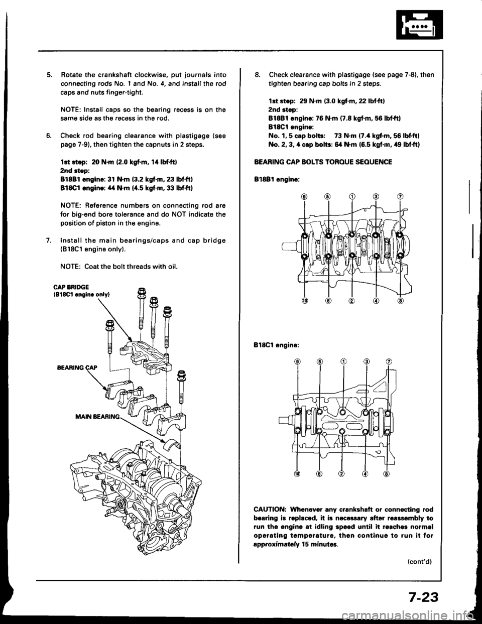
Install the main bearings/caps and cap b.idge(818C1 engine onlyl.
NOTE: Coat the bolt threads with oil.
CAP BRIDGElBlSCl .noin. onlyl
EEARIlTG
8. Check clearsnce with plastigsge (see page 7-8). then
tighten bearing cap bolts in 2 steps.
13t st.p: 29 N.m (3.0 kgf.m, 22 lbt.ftl
2nd 3tsp:
81881 .ngin.: 76 N.m (7.8 kgt.m,56 lbf,ft)
Bl8Ct engine:
No. 1, 5 cap bol$: 73 N.m (7./r kgf'm, 56 lbf,ftl
No. 2, 3, a clp bolbr 6{ N.m (6.5 kgf'm, /r9 lbf,ftl
BEARING CAP BOLTS TOROUE SEOUENCE
Bl88l cngino:
Bl8Cl ongino:
CAUTION: Whenever any crsnkehaft or connocting rod
b.aring is rlphccd. it i5 ncccrsrry aftor rclssombly to
run tho ongino ai idling 3p6ad until it re.chei normrl
opcrating tcmporature, thon continuo to run it fol
spp.oximltoly f 5 minula3.
(cont'd)
7-23
Page 169 of 1413
lllustrated Index
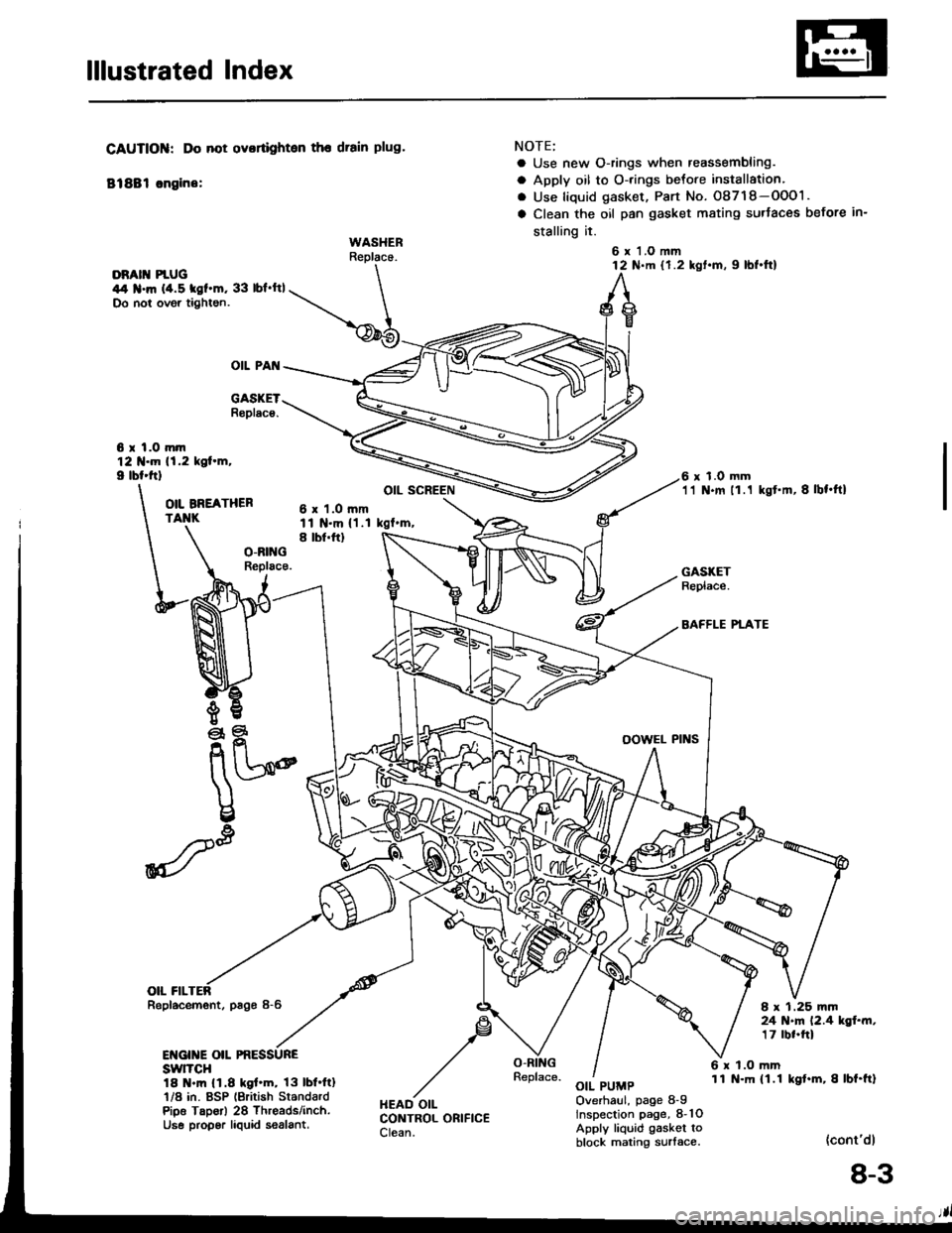
DRATT PIUG \44 .m (4.5 tgf.m, 33 lbf'ftl \Do not ovgr tightgn. \-@5
OIL PAI{
6 r l.O mtn121{.m 11.2 kol.m,I lbl.ttl
CAUTIOIiI: Do not ovortighten the drain plug.
81881 sngine:
WASHERReplace.
O|L BNEATHERTAIIK
eq
nU2o@
\
u
I
#-'
GASKETR6placs,
NOTE;
o Use new O-rings when reassembling.
a Apply oil to O-rings betore installation,
. Use liquid gasket, Part No. O8718-OOO1.
a Clean the oil pan gasket mating surtaces before in-
stalling it.
6 x'l.o mm12 N.m {1.2 kgt.m, 9 lbt.tt)
6 x 1.0 mm'11 N.m 11 .1 kgt'm,8lbt.ftl
6 x 1.O mmll N.m {1.1 kgf'm,
OIL SCREEN
A
,F
HEAD OILCONTROL ORIFICECIean.
I tbt.ftl
OIL FILRepl.cemont, p6gs 8-6
ENGINE OIL PRESSUREswlTcH18 .m 11.8 kgl.m, 13lbl.ftl'l/8 in. BSP lgritish StandardPioo Taporl 28 Threads/inch.Use propgr laquid 56alant.
GASKETReplace.
BAFFLE PTATE
I x 1.25 mm24 N.m 12.4 kgf..n,17 rbr.ftl
6 x 1.O mm11 N-m (1.1 kgt.m,8lbf.ft)OIL PUMPOverhaul, page 8-9lnspection page, 8-1OApply liquid gasket toblock mating surlace.(cont'dl
8-3
Page 170 of 1413
lllustrated Index
(cont'dl
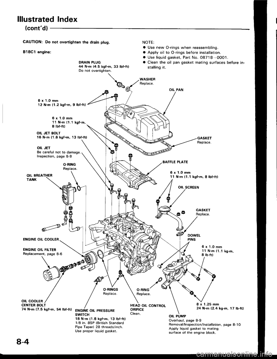
CAUTION: Do not overtighten rhe dlain ptug.
818C1 engine:
NOTE:
a Use new O-rings when reassembling.
a Apply oil to O rings before installation.. Use liquid gasket. Part No. 08718-OOO1.
a Clean the oil pan gasket mating surfaces before in-
stalling it.
OIL PAN
Replace.
6 x 1.0 mm12 N.m 11.2 kgl.m, 9 lbf.ftl
6 x 1.0 mm11 N.m 11.1 kgt.m,S lbf.fil
OIL JET BOLT16 N.m {'1.6 kgf.m, '13 lbf.ft}
OIL JETBe careful not to damage.Inspection, page 8-8
O-RINGReplace.
EAFFLE PLATE
6xl.0mm11 N.m (1.1 kgt.m, I lbt.ft)
OIL SCREEN
GASKETReplace.
6 r '1.0 mml1 N.m (1.18 rb-trlK9-m,
O-RINGReplace.
HEAD OIL CONTROLORIFICEClean.
8 x 1.25 mm24 N.m (2.4 kg-m, 17 lb-ft)ENGINE OIL PR€SSUREswtTcH1A N.m {1.8 kgf.m, 13 lbf.ft)1/8 in. BSP {British StandardPipe Taperl 28 threads/inch.Use proper liquid gasket.
OIL PUMPOverhaul, page 8-9Removal/lnspection/lnstallation, page 8-10Apply liquid gasket to matingsurface ot the engine block.
Il
,--)e6V
ENGINE OIL COOLER
ENGINE OIL FILTERReplacement, page 8-6
OIL COOLERCE TER BOLT74 N.m (7,5 kgf.m, 54 lbf.ft)
DRAIN PLUG44 N.m (4.5 kgf.m, 33 lbt.ftlDo not overtighten.
8-4
Page 174 of 1413
Oil Pressure
Testing
lf the oil pressure warning light stays on with the enginerunning, check the engine oil level. lf the oil level is
correct:
1. Connect a tachometer.
2. Remove the oil pressure switch and install an oil pres-
sure gauge.
3. Stan the engine. Shut it off immediately if the gauge
registers no oil pressure. Repair the problem before
continuing.
4. Allow the engine to reach operating temperatu,e {fancomes on at least twice). The Dressure should be:
Engine Oil Pressure:
At ldle: 70 kPa (0.7 kgf/cmr, 10 psi)
minimum
At 3,OOO lpm: 340 kPa {3.5 kgf/cmz, 50 psi}
minimum
a lJ oil pressure is within speciJications, replace the
engine oil pressure switch and recheck.
a lf oil pressure is NOT within specifications, in-
spect the oil pump (see page 8-1O).
1.2 mm 10.05 in)
'16 N.m (1.6 kgt.m, l2lbt.ftl
Oil Jet
Inspection (B18C1 engine only|
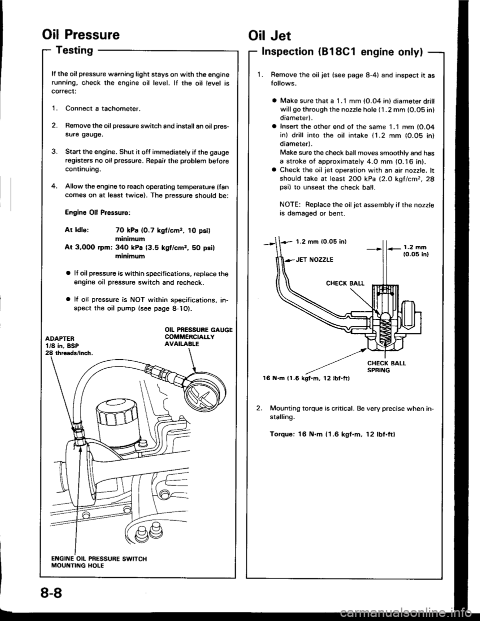
Remove the oil jet (see page 8-4) and inspect it as
follows.
a Make sure that a I .l mm (O.04 in) diameter drill
will go through the nozzle hole {1 .2 mm {O.OS in)
diameterl.
a Insert the other end of the same 1.1 mm (O.O4
in) drill into the oil intake {1.2 rnm {0.05 in}
diameter).
Make sure the check ball moves smoothlv and has
a stroke of approximately 4.0 mm {O. 16 in).a Check the oil jet operation with an air nozzle. lt
should take at least 2OO kPa (2.O kgf/cmr,28
Dsi) 10 unseat the check ball.
NOTE: Replace the oiljet assembly if the nozzle
is damaged or bent.
2. Mounting torque is critical. Be very precise when in-
stalling.
Torque: 16 N.m (1.6 kgt.m, 12lbf.ftl
OIL PRESSURE GAUGECOMMERCIALLYAVAILABI.E
8-8
Page 175 of 1413
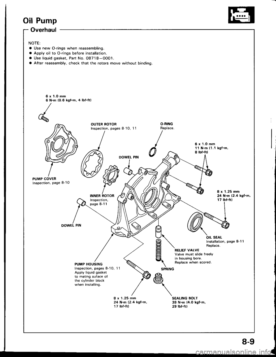
Oil Pump
Overhaul
NOTE:
a Use new O-rings when reassembling.
a Apply oil to O-rings before installation.
. Use liquid gasket, Part No. 08718-OO01.
a After reassembly, check that the rotors move without binding.
6 x 1.0 mm6 N.m 10.6 kgl.m, 4 lbt'ttl
OUTER ROTORInspection, pages I 10, 11O.RINGReplace.
0
6 x 1.O mm11 N.m (1.1 kgf.m,8 tbf.frl
DOWEL PIN
PUMP COVERInspection, page 8-10
INNER ROTORInspect|on,page 8-1 1
8 x 1.25 mm24 N.m (2.4 kgf.m,t7 tbt'ft)
\SPRING
OIL SEALInstallation, Page 8-1 1Replace.
RELIEF VALVEValve must slide treelyin housing bore.Replace when scored.PUMP HOUSINGlnspection, pages 8-10, 11Apply liquid gasketto mating suface oIthe cylinder blockwhen installing.*\
8 x 1.25 mm24 N.m (2.4 kgl.m,17 lbl.Irl
SEALING BOLT39 N'm 14.0 kgf.m,29 tbt.ttt
Page 186 of 1413
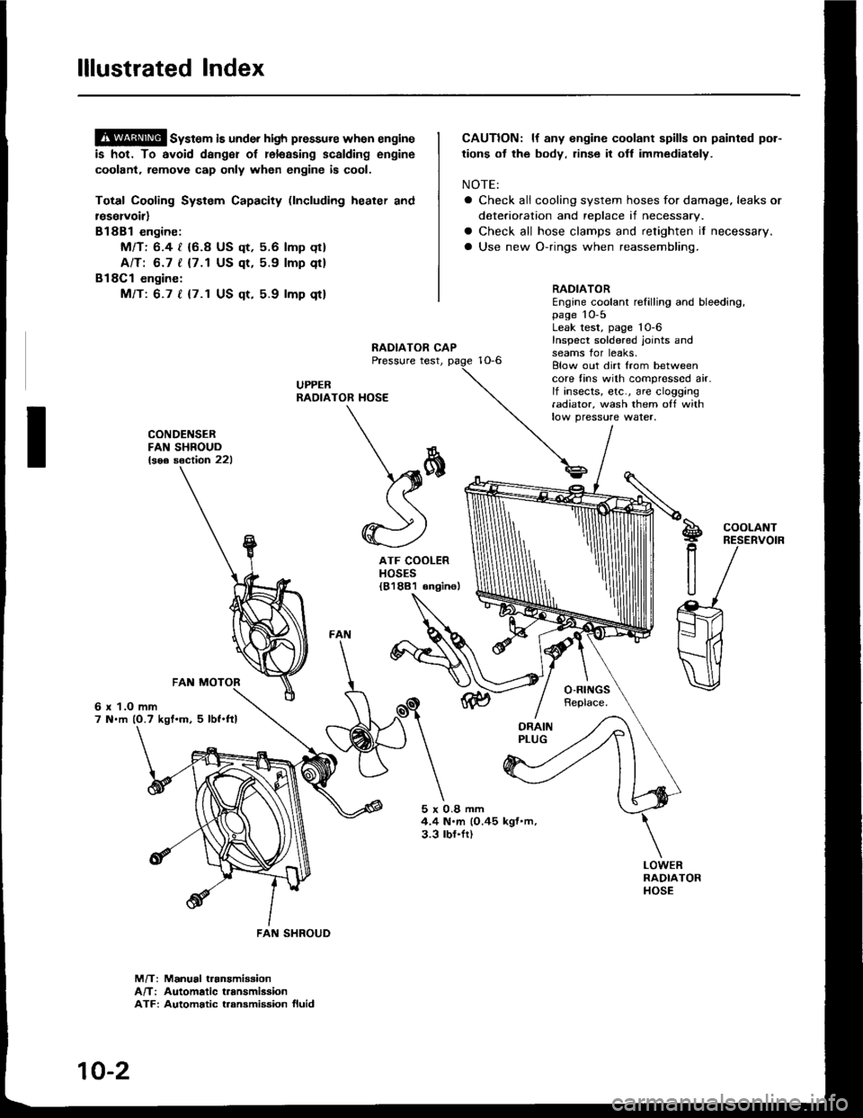
lllustrated Index
@ sy"t". is under high plessure when engine
is hot. To avoid dsnger of relsssing scalding engine
coolant. remove cap only when engine is cool.
Total Cooling System Capacity (lncluding heater and
r€servoirl
Bl8Bl engine:
Mfl: 6.4 | {6.8 US qt, 5.6 lmp qt}
AlTt 6.7 | {7.1 US qt, 5.9 lmp qt}
Bl8Cl engine:
Mfi: 6.7 t {7.1 US qt, 5.9 lmp qt}
CAUTION: lf any engine coolant spills on paint€d por-
tions ot the body, rinse it ofl immediately.
NOTE:
a Check all cooling system hoses for damage. leaks or
deterioration and replace if necessary.
a Check all hose clamps and retighten if necessary.
a Use new O-rings when reassembling.
CONDENSERFAN SHROUD{soe soction 221
6 x 1.O mm7 N.m (O.7 kgt.m. 5 lbf.ftl
ATF COOLERHOSES{81881 6ngine)
RADIATOREngine coolant refilling and bleeding,page 10-5Leak test, page 'l0-6
Inspect soldered joints andseams for leaks.Elow out dirt from betweencore fins with compressed air.lf insects, etc., are clogging.adiator, wash them off withlow pressure water,
S!
P
R
U
COOLANTRESERVOIR
5x0.8mm4.4 N.m (O.45 kgf.m,3.3 lbl.fr)
M/T: Manual t.anamiaaionA/T: Automatic t.ansmiasionATF: Automatic t.ansmission fluid
\*
*)
FAN SHROUD
10-2
Page 192 of 1413
![HONDA INTEGRA 1994 4.G Repair Manual Water Pump
NOTE:
a Use new O-rings and new special bolts when reassembling.
a Use liquid gasket, Part No. O8718-0OO1.
3;iil3 B18c1 onsino:
ECT GAUGE SEDING U]{ITI N.m (0.9 tgf.n, 7 lbftt)Apply liquid HONDA INTEGRA 1994 4.G Repair Manual Water Pump
NOTE:
a Use new O-rings and new special bolts when reassembling.
a Use liquid gasket, Part No. O8718-0OO1.
3;iil3 B18c1 onsino:
ECT GAUGE SEDING U]{ITI N.m (0.9 tgf.n, 7 lbftt)Apply liquid](/img/13/6067/w960_6067-191.png)
Water Pump
NOTE:
a Use new O-rings and new special bolts when reassembling.
a Use liquid gasket, Part No. O8718-0OO1.
3;iil3 B18c1 onsino:
ECT GAUGE SEDING U]{ITI N.m (0.9 tgf.n, 7 lbf'tt)Apply liquid gaskot
to tho threads.
6r1.Omm
ENGI E COOLAI{TTEMPERATURE IECTI SENSORt8 N.m 11.8 kot.m, 13lbt'ttl
1l t{.m ll.1 tgl.m.8.O tbt.ftl
lllustrated Index
WATER PUMPInspectaon,page lO-9
KNOCK SEI{SOR3l N.m {3.2 kgf.m.23 tbf.ftl(8l8Cl .ngin€ onlyl
WATER OUTLETCOVERApply liquid gasket
to mating sudace.
ECT SEI{SOR
6 r 1.0 mm11 N.m l1.l kgl.m,8.O lbl.ftl
BLEED BOLT9.8 N.m (l.O rg[.m. 7.2 lbt'ft|
Bl8Bl cngln :
OUTIET
ECT SIY]TCH22-26 .m 12.2-2.C )l{/l'nt.
16-19 tbr.ftl
o-Rtt{GRoplaco.
o-itltcRoplrco.
8r1.Orxtr12 .|n ll.2 lgt.m,8.7 n{.ftt
6xt.Omm12 N'ft (1.2 kgf..n.8.7 lbt.ft)
10-8
Page 193 of 1413
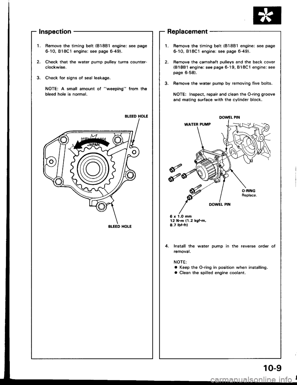
Inspection
Remove the timing belt (81881 engine: see page
6-1O, B18C1 engine: see page 6-49).
Check that the water pump pulley turns counter-
clockwise,
Check for signs ol seal leakage.
NOTE: A small amount ot "weeping" from the
bleed holo is normal,
BLEED HOLE
2.
J.
J.
Replacement
6 r 1.O rnm12 N.m {1.2 kgf.m,4.7 bf.ftl
4. lnstall the water pump in the reverse order
removat.
NOTE:
a Keep the O-ring in position when installing.
a Clean the spilled engine coolant.
Remove the timing belt (818B1 engine: see page
6-10,818C1 engine: see page 6-49).
Remove the camshaft pulleys and the back cover(81881 engine: see page 6-19. B18C1 engine: see
page 6-581.
Remove the water pump by removing five bolts,
NOTE: Inspect, repair and clean the O-ring groove
and mating su.lace with the cylinder block.
DOWEL PIN
BI-EED HOI-E
10-9
Page 195 of 1413
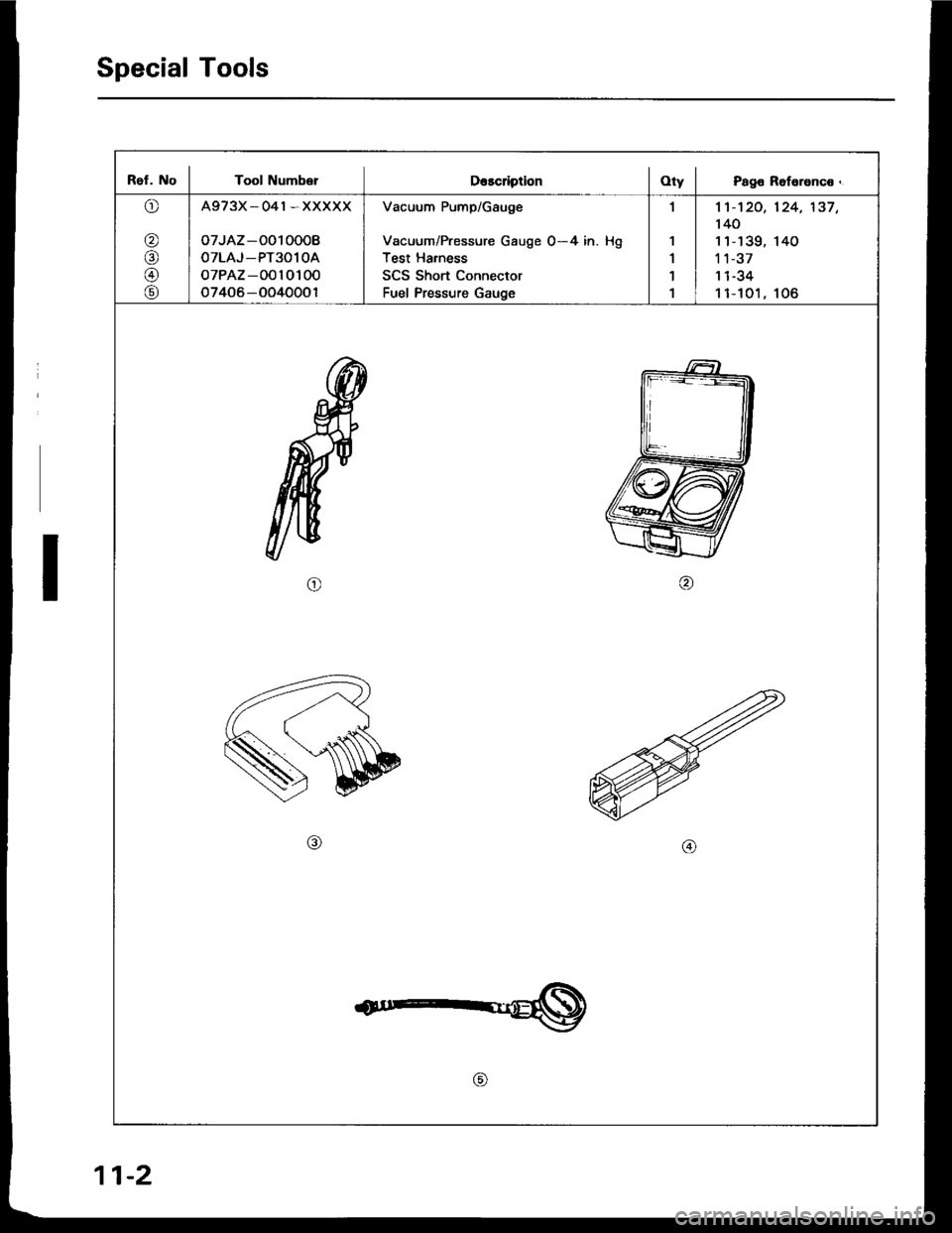
Special Tools
Ref. No I Tool Numb€rDescription I OtV I Page Reference.
o
@
@
@
@
A973X_041*XXXXX
oTJAZ -O010008
OTLAJ_PT3O1OA
oTPAZ-0010100
o7406-OO40001
Vacuum Pump/Gauge
Vacuum/Pressure Gauge 0-4 in. Hg
Test Harness
SCS Short Connector
Fuel Pressure Gauge
,l
1
1'l
1
1't -'t 20,
140
11-139,'t 1-37
I t -J.+
11-t01,
124,'137,
140
106
o
11-2
Page 196 of 1413
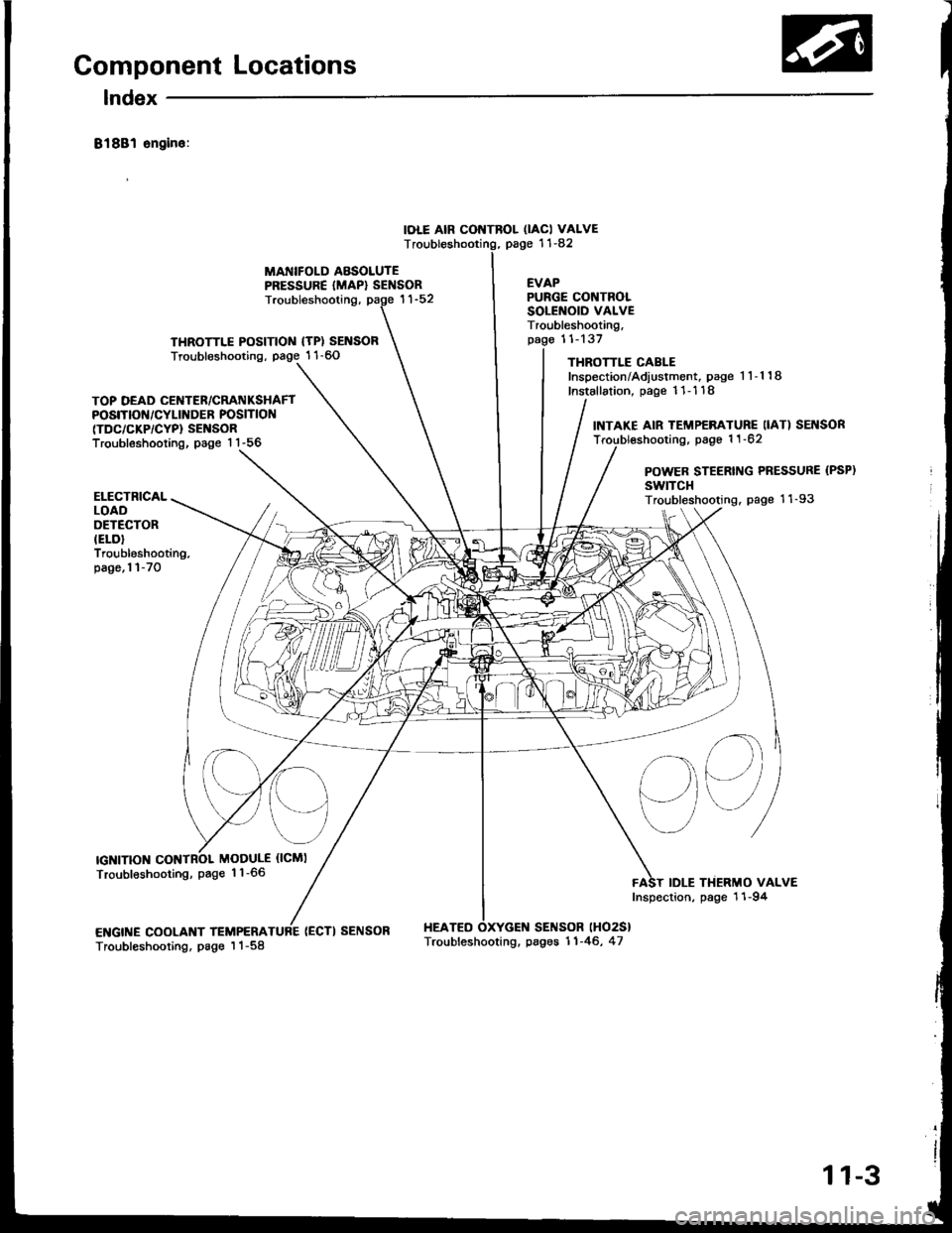
Component Locations
lndex
81881 sngin6:
IOLE AIR CONTROL OACI VALVEpage '11-82T
MANIFOLD ABSOLUTEPRESSURE {MAP} SENSOREVAP
THROTTLE POSITIOIII {TP) SENSORTroubleshooting, page 1 1-60
Troubleshooting,
(ECTI SENSOR HEATEO
PURGE CONTROLSOLENOID VALVETroubleshooting,11-137
THROTTLE CABLEInspection/Adiustment, page 1 1-1 18
Installation, page 11- 1 18
SENSOR lHO2S}
TOP DEAD CENTER/CRATIIKSHAFTPOSITIOf{/CYLINDER POSITION(TDC/CKP/CYP} SENSORTroubleshooting, page 1 1-56
INTAKE AIR TEMP€RATURE IIAT) SEI{SORTroubl€shooting, page 1 1 -62
POWER STEERING PRESSURE (PSP)
swtTcHTroubleshooting. page 11-93
sq
IDLE THERMO VALVEInspection, page 11-94
ELECTRICALLOADOETECTORIELD}Troubleshooting.page,l l-70
IGNITIONMODULE {ICMI
Troubleshooting, page 1 1-66
ENGINE COOLANT TEMPERATroubleshooting, page I 1-58Troubleshooting. pages 11-46, 47
11-3