Page 98 HONDA INTEGRA 1994 4.G Manual PDF
[x] Cancel search | Manufacturer: HONDA, Model Year: 1994, Model line: INTEGRA, Model: HONDA INTEGRA 1994 4.GPages: 1413, PDF Size: 37.94 MB
Page 197 of 1413
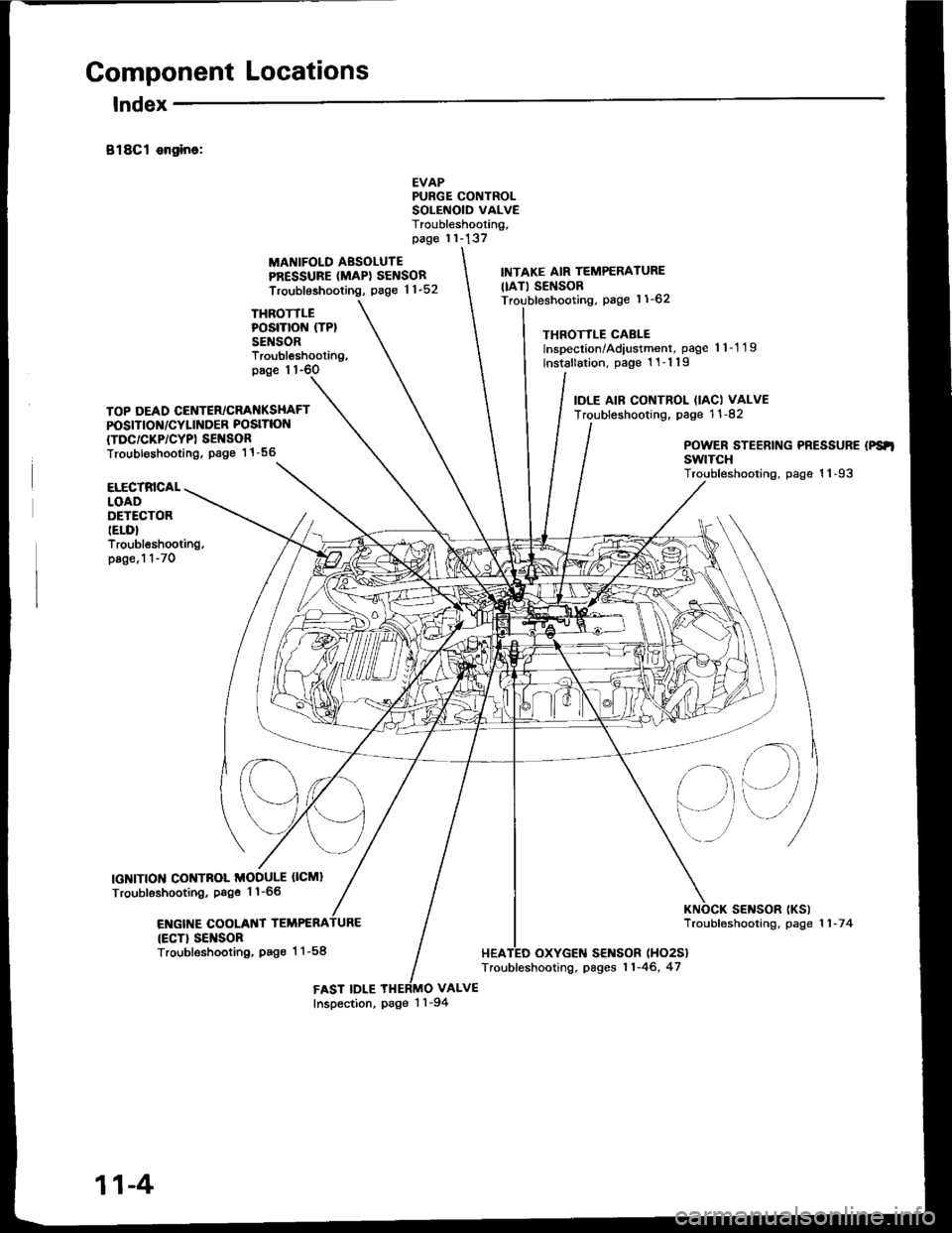
Component Locations
lndex
B18Cl ongino:
THROTTLEPOSITION (TP}
SENSOR
MANIFOLD AESOLUTEPRESSURE (MAPI SENSOR
Troubleshooting, page 1 1-52
EVAPPURGE CONTROLSOLEiIOID VALVETroubleshooting,page 11-137
VALVE
INTAKE AIR TEMPERATURE
IIAT) SENSORpage 11-62
THROTTLE CABLEInspection/Adiustment, page 'l 1-1 19
lnstallation, page 1 1-1 19
IOLE AIF CONTROL (IACI VALVETroubleshooting. page 1 1 -82
Troubleshooting,page 1 1-6O
TOP DEAD CENTER/CRANKSHAFTPOSITION/CYLINDER POSITION
{TDC/CKP/CYPI SEI{SORTroubl€shooting. Page 1 1 -56POWER STEERING PRESSURE (PS'I
swtTcHTroubleshooting, page 1 1-93ELECTRICALLOADDETECTORIELD}Troubleshooting,page.1 1-70
IGNITION CONTNOL MODULE OCMI
Troubleshooting, Psge 1'l-66
ENGIT{E COOLANT TEMPERA
{ECT} SEI{SORTroubleshooting, Pag€ 1 1-58
sElrlsoR tKslTroubfeshooting, page 1 1 -7 4
HEATED OXYGEN SENSOR (HO2S}
Troubleshooting, pages 11-46, 47
FAST IDLEInspection, page 1 'l -94
11-4
Page 198 of 1413
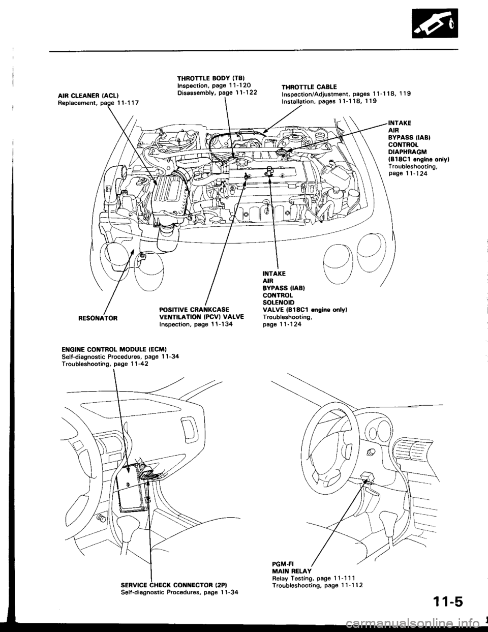
AIR CLEAI{ER IACL)Replacoment,11-117
THROTTLE BODY (T8I
Inspsction, page 1 1-120Disassembfy, page 11'122THROTTLE CABLEInsDection/Adjustment, pages 1 l-'l 18, 1 19
Inslallation, pages 1 1-1 18, 119
POSITIVE CRA KCASEvEt{TtLATtOt{ (PcVl VALVEInspection, psgo 1 l-134
INTAKEAIREYPASS IIABIco TnoLSOLENOIDVALVE (B18Cl .ngino onlylTroubl6shooting,page 1 1-124
INTAKEAIRBYPASS (IABI
co TROLOIAPHRAGM{Bl8C1 ongino onlylTroubleshooting,page 11-124
I
RESONATOR
ENGI]TE CONTROL MODULE {ECM)Selt-diagnostic Procedures, page 1 1-34Troubfeshooting, page 1 1 -42
MAIN RELAYRelay Testing, page 1 1- 111Troubleshooting, pag€ 1 1-112SERVICE CHECX CONNECTOR (2PI
56ll.diagnostic Procedures, page'l 1-34
11-5
Page 199 of 1413
![HONDA INTEGRA 1994 4.G Manual PDF System Description
Index
FUEL FILTERReplacement, page 11- l OB
FUEL II{JECTORSTroubleshooting, page 1 1-102Replacemont, page 1 1-105
FUEL FEED PIPE
FUEL GAUGE SE]IIDING U]{ITTgsting, s€ction 23
FU� HONDA INTEGRA 1994 4.G Manual PDF System Description
Index
FUEL FILTERReplacement, page 11- l OB
FUEL II{JECTORSTroubleshooting, page 1 1-102Replacemont, page 1 1-105
FUEL FEED PIPE
FUEL GAUGE SE]IIDING U]{ITTgsting, s€ction 23
FU�](/img/13/6067/w960_6067-198.png)
System Description
Index
FUEL FILTERReplacement, page 11- l OB
FUEL II{JECTORSTroubleshooting, page 1 1-102Replacemont, page 1 1-105
FUEL FEED PIPE
FUEL GAUGE SE]IIDING U]{ITTgsting, s€ction 23
FU€L
FUEL PUMPT€sting. page 11- 1 10Roplscam€nt. page 11-l 10
FUEL FIIL CAP
FUEL TA KR6placomont,page l1-114
EVAFORATIVE EMISSIONIEVAP} TWO WAY VALVETesting, pag€ 11-140
EVAPORATIVEEMTSStOt{{EVAP} PURGECONTROL DIAPHNAGMVALVETroubleshooting, page'l 1-137
PNESSURE REGUIATORTesting, page 11-106Roplac€m€nt, page 1 1-107
FUEL RAIL
EVAFORATIVC EMISSION(EVAPI COI{TROL CANISTERTroubl6shooting. pag6 1 1-'l 37
FUEL VAFON APE
11-6
Page 224 of 1413
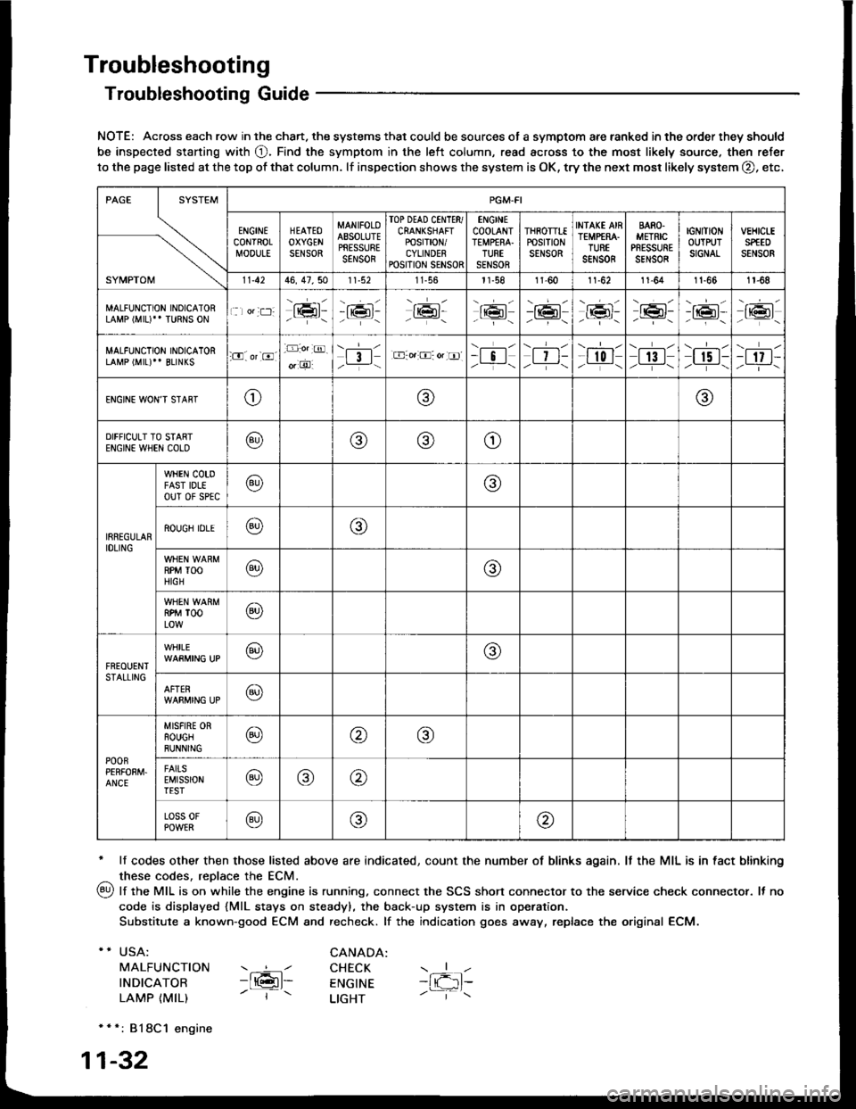
Troubleshooting
Troubleshooting Guide
NOTE: Across each row in the chart. the systems that could be sources of a symptom are ranked in the order they should
be inspected staning with O. Find the symptom in the left column, read across to the most likely source. then refer
to the page listed at the top of that column. lf inspection shows the system is OK, try the next mosr likely system O, etc,
* lf codes other then those listed above are indicated, count the number of blinks again. It the MIL is in fact blinking
^ these codes, replace the ECM.
qy, lf the MIL is on while the engine is running. connect the SCS shon connector to the service check connector. It no
code is displayed {MlL stays on steady), the back-up system is in operation.
Substitute a known-good ECM and recheck. lf the indication goes away, replace the original ECM.
USA:
MALFUNCTION
INDICATOR
LAMP {MIL)
CANADA: ----l CHECK-ltGl- ENGTNE- | - LTGHT
- { -1t-
* * *: 818C1 engine
1-32
SYMPTOM
PGM.FI
ENGINECONTROLMOOULE
HEATEOOXYGENSENSOR
MANIFOLOAESOLUTEPRESSURESENSOR
TOP DEAD CINTTR/CRANKSHAFTPOSTT|ON/CYLINDERPOSITION SENSOR
ENGINECOOLANTTEMPfRA.TURTSENSOR
THROTTTEPOStTtONSENSOR
INfAKE AIRTEMP€RA.TUREsar,rs0R
BARO.METRICPRESSURESENSOR
IGNITIONOUTPUTSIGNAL
vEHtct-ESPfEDSENSOR
11.4246, 47,5011-56l1-581l-6011-6211-641t-661r-68
MALFUNCTION INOICATORLAMP (MIU" TURNS ON1 lor:t:]:lrmr:- i;:i'-tK3t-16l-16l'-\-16l/-----\
-r:+r-
-{"Pr:-o_-16l-.z-\r6t/_-\
MALFUNCTION INOICATORLAMP (MIL)'' BLINKS:O. or-8.-D:o.:@.
o, O'l3l/__-\.E-o.:O: or tr]--i !l/ -i-\| 7 t-/__-\
--l-l-l r0 I/----\| 13 |z_---\
\.--r--l
I r5 t-/.---\-t 17 t-/-]-\
ENGINE WON'T STAffTo@@
DIFFICULT TO STARTENGIN€ WHEN COLO@@(9)o
IRREGULARIDLING
WHEN COTDFAST IDLEouT 0f sPtc@@
ROUGH IDLE@o
RPM TOOHIGH@@
RPM TOOLOW@
FREOUENTSTALLING
WHILE@@
AFTER@
POOnPERFOEM.ANCE
MISFIRE ORROUGHRUNNING@@@
FAITSEMISSIONTEST@@@
Loss 0FPOWER@@@
Page 228 of 1413
Troubleshooting
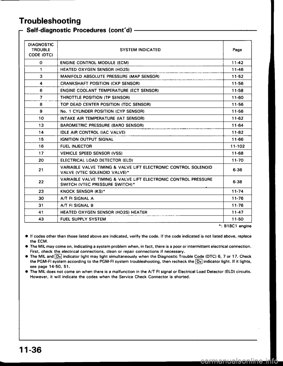
Self-diagnostic Procedures (cont'dl
':818C1 engine
a lf codes other than those listed above are indicated, verifv the code. lf the code indicated is not listed above, replace
rhe ECM.
a The MIL may come on, indicating a system problem when, in fact, there is a poor or intermittent electricalconnection.
First, check the electrical connections, clean or repair connections it necessary.
o The MIL and @ indicator light may light simultaneously when the Diagnostic Trouble Code (DTC) 6, 7 or 17. Check
the PGM-Fl system according to the PGM-Fl system troubleshooting, then recheck the l!! indicator light. ll it lights,
see page 14-5O, 51.
a The MIL does not come on when there is a malfunction in the A/T Fl signal or Electrical Load Detector (ELDI circuits.
However, it will indicate the codes when the Service Check Connector is shorted.
DIAGNOSTIC
TROUBLE
CODE (DTCISYSTEM INDICATEDPsge
oENGINE CONTROL MODULE IECM)11-42
,lHEATED OXYGEN SENSOR IHO25)1 1-46
aMANIFOLD ABSOLUTE PRESSURE {MAP SENSOR)11-52
4CRANKSHAFT POSITION (CKP SENSOR)1 1-56
oENGINE COOLANT TEMPERATURE (ECT SENSOR)11-58
THROTTLE POSITION (TP SENSOR}11-60
ITOP DEAD CENTER POSITION (TDC SENSORI1 1-56
9No. 1 CYLINDER POSITION (CYP SENSOR)1 1-56
10INTAKE AIR TEMPERATURE (IAT SENSOR)11-62
13BAROMETRIC PRESSURE (BARO SENSOR}1|-64
14IDLE AIR CONTROL (IAC VALVE}11-42
tcIGNITION OUTPUT SIGNAL11-66
toFUEL INJECTOR1't-102
17VEHICLE SPEED SENSOR {VSSI11-68
20ELECTRICAT LOAD DETECTOR (ELD)'t 1-70
21VARIABLE VALVE TIMING & VALVE LIFT ELECTRONIC CONTROL SOLENOID
VALVE {VTEC SOLENOID VALVE)'6-36
22VARIABLE VALVE TIMING & VALVE LIFT ELECTRONIC CONTROL PRESSURE
SWITCH (VTEC PRESSURE SWITCHI-6-38
23KNOCK SENSOR {KS}-11-7 4
30A/T FI SIGNAL A11-76
3'rA/T FI SIGNAL B1 1-76
4'lHEATED OXYGEN SENSOR (HO25} HEATER11-47
43FUEL SUPPLY SYSTEM1 1-50
11-36
Page 229 of 1413
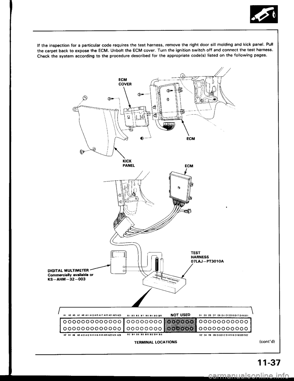
It the inspection for a particular code requires the test harness. remove the right door sill molding and kick panel. Pull
the carpet back to expose the ECM, Unbott the ECM cover. Turn the ignition switch off and connect the test harness
Check the system according to the procedure described for the appropriate code(s) listed on the following pages.
KICKPANEL
TESTHARNESSOTLAJ _PT3OlOA
DIGITAL MULTIMETERCommarcially ovribbla orKS-AHM-32-OO3
NOT USED
TERMINAL LOCATIONS(cont'd)
o oooooooooooo
ooooooooooooo
oo o oo ooo
oooooooo
ooooooooooo
ooooooooooo
11-37
Page 235 of 1413
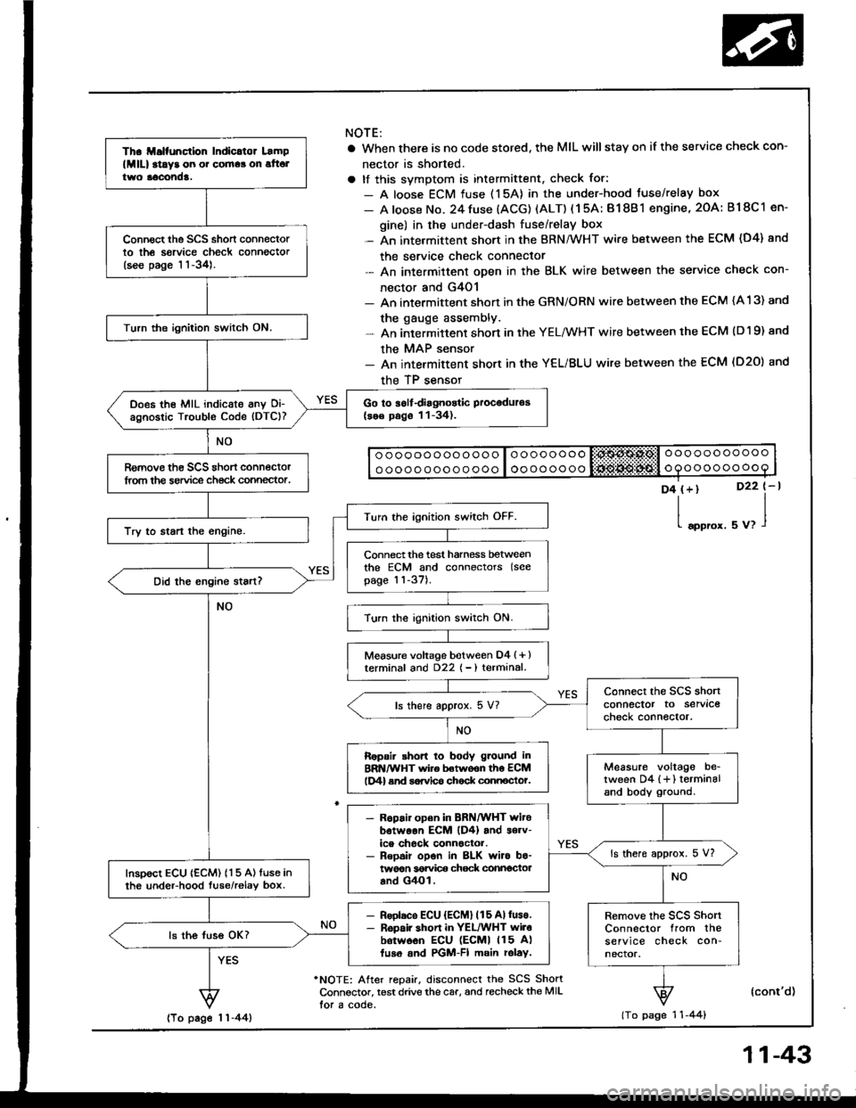
Th. ll.lfunction Indicltor Lamp
lMlll at!y3 on o. cornaa on alt6ltwo aacond!.
Connect the SCS short connectorto th6 sorvice check connector(see page 11-34).
Turn the ignition switch ON.
Go to iolfdiagnostic Proceduros(se€ pago 11-34).Does the MIL indicate anv Oi-agnostic Trouble Code (DTC)?
Romove th€ SCS shon connectorlrom the service ch€ck connector.
Turn the ignition switch OFF.
Try to start the engine.
Connect the test harness betweenthe ECM and connectors (see
page 11-37).
Turn the ignition switch ON.
Measure voltage botween D4 (+ )terminal and D22 { - ) terminal.
connect the SCS shonconnector to servlcecheck connector.ls there approx. 5 V?
Ropair shon to body g.ound inBRN/WHT wire betwoon th6 ECMlD4) end sorvlco chock connocto?.Measure voltage be_tween D4 {+} terminaland body ground.
- R6pair open in BRN/WHT witobotwoon EcM lD4) and s6rv-ice chock connactor.- Repoir opon in BLK wiro bo-twoon 36rvi@ chock connectoaand G4Ol.
ls there approx. 5 V?
InsDoct ECU {ECM) 115 A) tuse inth6 undeFhood luse/relav box.
- Rsolaco ECU {ECM} (15 Allus€.- R6pair shon in YEL/WHT wilobotw6on ECU lEcMl 115 A)fuso and PGM-FI main rolay.
Remove the scs shortConnector from theservice check con-nector.
ls the luss OK?
NOTE:
a When there is no code stored, the MIL willstay on if the service check con-
nector is shorted.
a tf this svmotom is intermittent, check for:
- A loose ECM fuse (15A) in the under-hood tuse/relay box
- A loose No. 24 fuse (ACG) (ALT) ( 1 5A: B1 8B 1 engine, 2OA: B18C 1 en-
gine) in the under-dash fuse/relay box- An intermittent short in the BRN/WHT wire between the ECM (D4) and
the service check connector- An intermittent oDen in the BLK wire between the service check con-
nector and G4O1- An intermittent shon in the GRN/ORN wire between the ECM (A 13) and
the gauge assembly.- An intermittent short in the YELMHT wire between the ECM (D19) and
the MAP sensor- An intermittent short in the YEL/BLU wire between the ECM (D20) and
the TP sensor
o ooooo ooo ooo o loooooooo liii:$A$.Ps,l o oo ooo ooooo
o oooo ooo o o ooo I oooooooooooooooooo
D4 (+)
l"oo,o'.
D22 t-l
uu,l
'NOTE: After repair, disconnect the SCS ShortConnsctor, test drive the car, and recheckthe MIL
lor a code.
(cont'd)
(To page 1 'l -44)lTo page 1 1-44)
11-43
Page 236 of 1413
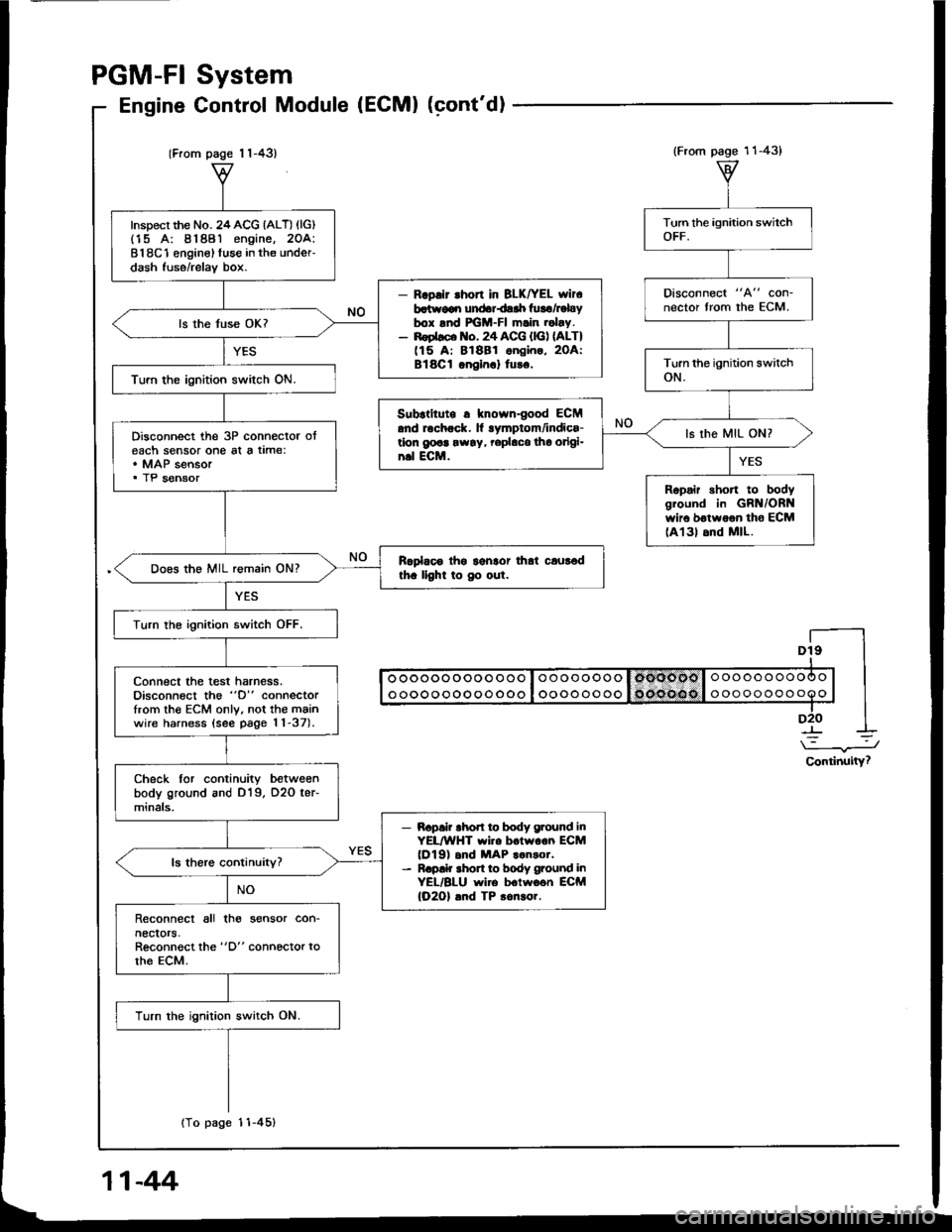
(From page 1 1-43)
Inspect the No. 24ACG {ALT) (lG)(15 A: 81881 engine, 2OA:818C1 enginel fuse in the under-dash fuse/relav box.
- R.pllr .hon in BLK|rEL wlr6batr.v€qr undariair luro/Fbybox lnd FGM-FI m.in .obv.- noebco lto. 24 ACG {lG) nLT)(15 A: 81881 ongin., 2OA:Bl8Cl onein.l tu!6.
ls the fuse OK?
Turn the ignition switch ON.
Disconnect the 3P connector oteach sensor one al a time:. MAP sensor. TP sensor
Rcplaoo thg lgnlor that caur6dth. llght to Oo out.Does the MIL remain ON?
Turn the ignition switch OFF.
connect the test harness.Disconnect the "D" connectorfrom th€ ECM only, not the mainwire harness (see page 11-37).
Check tor continuity betweenbody ground and D19, O2O ter-minals,
- Bapai? rhod ro body g.ound inYEL/WHT wi.e boiwoon ECM(Dl9) .nd MAP ..n3or.- R.p!k shon to body ground inYEL/BLU wire b.lwo6n ECM(O2Ol .nd TP 3on!or.
Reconnect all tho sensor con-necrors,Reconnect the "D" connector torhe ECM.
Turn the ignition switch ON.
{To page 11-45}
System
Control Module (ECMI (cont'dl
PGM-FI
Engine
Dt9I
I oooooooooo ooo I oooooooo I omoool o oooooooooo | |I ooooooooooooo I oooooooo 1o('oe(lo I ooooooooooo | |-lD2O I
\-.J
Continuity?
(From page 11-43)
Disconnect "A" con-nector from the ECM.
Subrtltute r knowngood ECM.nd rochock. ll lymptom/indics-tlon g@a rw!y, rephco tho origi-n.l ECM.
ls the MIL ON?
Ropair short to bodygiound in GRN/ORNwir6 botwoon tho ECMlA131 6nd MlL.
11-44
Page 237 of 1413
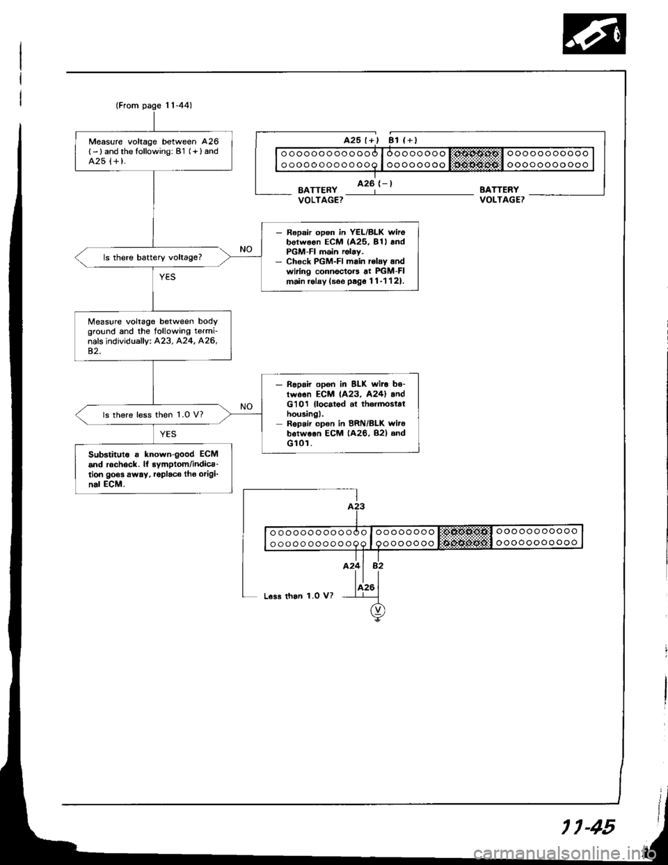
(From page 1l-44)
Measure voltage between 426
{- ) and the following: B'1 (+ } andA25 {+ t.
- Ropsir opon in YEL/BLK wirobotwoon ECM (425, 81l andPGM-FI m6in relay.- Chock PGM-FI main rclay andwiring connectors at PIGM-FImain.olay (soe psg6 11-1121.
ls there battery voltage?
Measure voltage between bodyground and the tollowing termi-nals individually: A23. A24, A26,42.
- noprir opon in BLK wit. b6-twson ECM 1A23, A24l andG'101 {locatod al th6.mostathousingl.Repair opon in BRN/BLK witebotweon ECM (A26, B2l andGl0r.
ls there less then 1.0 V?
Substitut6 r known{ood ECM
and r6chock. lf symptom/indica-tion goos away, roplaco tho origi-nal ECM.
BATTERYVOLTAGET
ooooooooooo
oooooooooooooooooooooo
ooooooooooo
oooooooo
ooooooo
L€ss than 1.0 V?
11-45
Page 239 of 1413
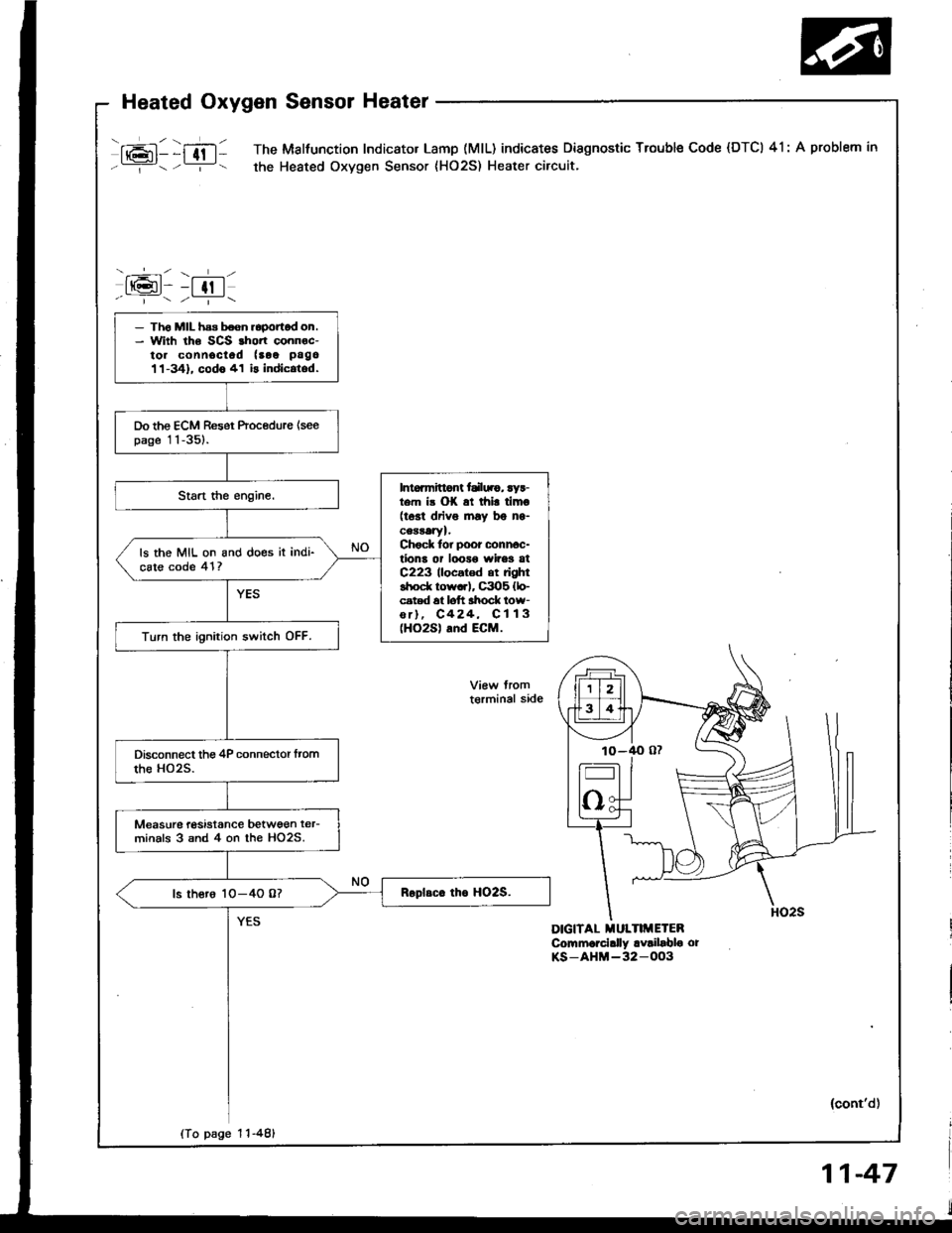
mll )ffltl The Malfunction Indicator Lamp (MlL) indicates Diagnostic Trouble Code (DTCI 41: A problem in
Y- -:- the Heated Oxygen Sensor {HO2S) Heater circuit.
-.----r- \- l-l
tt(gt- -t tt I-r---7r
DIGITAL MULTIMETEBCommorcially availablo orKS-AHM-32-OO3
- Th6 MIL has boen roponod on.- With the SCS rhort connoc-to. connociod (aoe pago
11-341. codo 41 is indic.tod.
Do the ECM Reset Procedure {seepage 11-351.
Intoamittont tdl||.g, ryr-t m i3 OK at thi! timo(tost driv6 lnay bg ns-cearatYl.Chock tor poor conn6c-tions or looro wires atC223 llocatod at rightshod( row..l, C3O5 {lo-cated 6t loft ahock low-or), C424, C113(HO2S) and ECM.
ls the MIL on and does it indi-cste code 41?
Turn the ignition switch OFF.
Measurc tasistance betwgen ter-minals 3 snd 4 on the HO2S.
ls thero 1O-4O 0?
t€rminal side
(To page 1 1-481
(cont'd)