HONDA INTEGRA 1994 4.G Repair Manual
Manufacturer: HONDA, Model Year: 1994, Model line: INTEGRA, Model: HONDA INTEGRA 1994 4.GPages: 1413, PDF Size: 37.94 MB
Page 61 of 1413
il
I
I
I
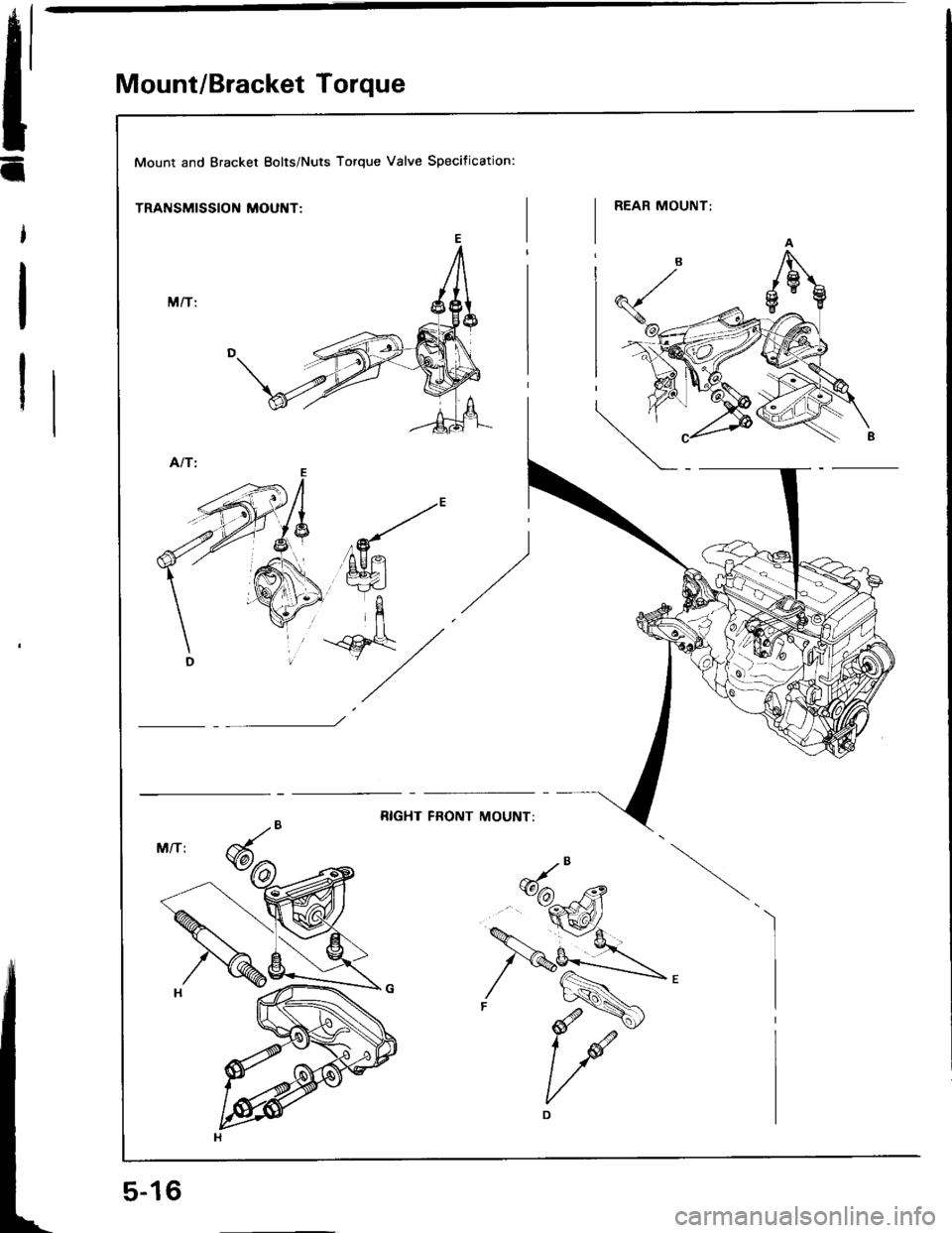
Mount/Bracket Torque
Mount and Bracket Eolts/Nuts Torque Valve Specification:
TRANSMISSION MOUNT:
Page 62 of 1413
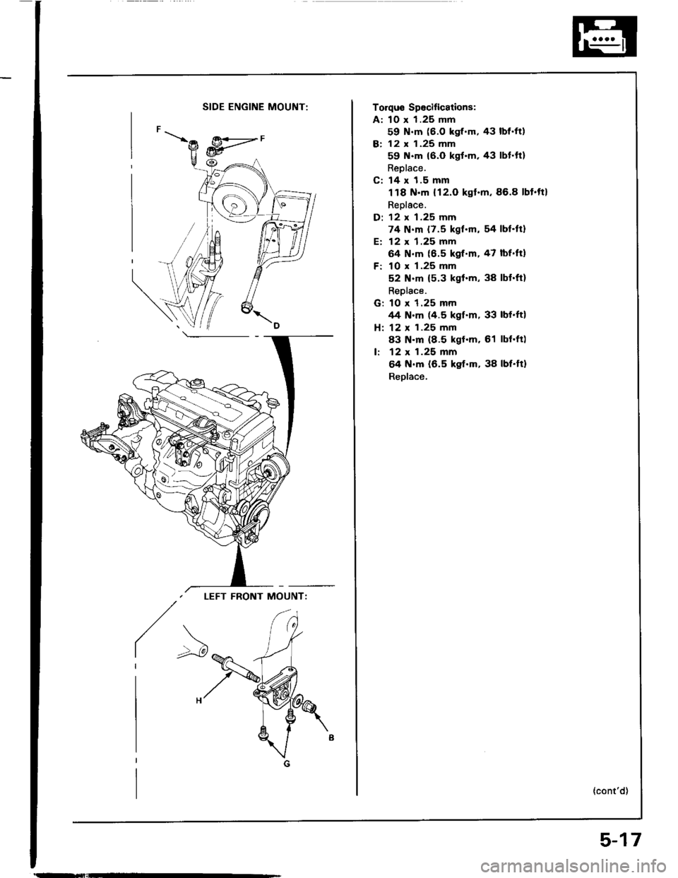
SIDE ENGINE MOUNT:
LEFT FRONT MOUNT:
/>
Torqus Spocifications:
A: 10 x 1.25 mm
59 N.m (6.O kgf.m, 43 lbf.ft)
B: 12 x 1.25 mm
59 N.m {6.0 kgt.m. 43 lbt.ft}
Reolace.
C: 14 x 1.5 mm
118 N.m {12.O kgt.m,86.8 lbt.tt}
Replace.
D: 12 x 1.25 mm
74 N.m {7.5 kgf.m, 54 lbf.tt}
E: 12 x 1.25 mm
64 N.m (6.5 kgf.m, 47 lbf.ftl
F: 10 x 1.25 mm
52 N.m {5.3 kgl.m, 38 lbt.ft}
Replace.
G: 10 x 1.25 mmrt4 N.m (4.5 kgf.m, 33 lbf.ft)
H: 12 x 1.25 mm
83 N.m (8.5 kgt.m. 61 lbl.ft)
lr 12 x 1.25 mm
64 N.m (6.5 kgf.m, 38 lbf.tt)
Reolace.
{cont'd)
5-17
Page 63 of 1413
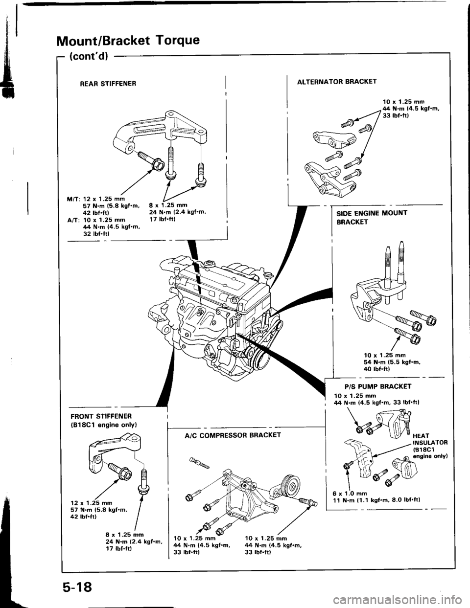
Mount/Bracket Torque
(cont'd)
REAR STIFFENER
M/T: 12 x '1.25 mm57 N.m 15.8 kgf'm,42 rbf.ft)A/T: 10 x 1.25 mm/14 N.m {4.5 kgf.m,32 tbt.ftl
ALTERNATOR BRACKET
10 x 1.25 mm
8x1.25mm24 N.m 12.4 kgf'm,
17 tbt.ftt
lO r 1.25 mm54 N'm (5.5 kgl.m,40 tbf.ft)
FRONT STIFFENER
(B18Cl engin€ onlyl
'12 x 1 .25 mm
f--^,c*;"*".*-
t-*i;
lq
I -4M
- Ghinein"onvt
ddv
HEATINSULATOR(818C1
P/S PUMP BRACKET
10 x 1.25 mm44 N.m (4.5 kgf'm, 33 lbf'ft|
57 N.m 15.8 kgt.m,42 tbf.fr)
8 x 1.25 mm24 N.m (2.4 kgf.m,17 tbf.ft)
10 x 1.25 mm 10 x 1.25 mnl44 N.m {4.5 kgf.m, 44 N.m (4.5 kgf.m,33 rbr.ftt 33 rbr.tt)
SIDE ENGINE MOUNT
BRACKET
5-18
'11 N.m (1.1 kgl'm,8 O lbf'tt)
Page 64 of 1413
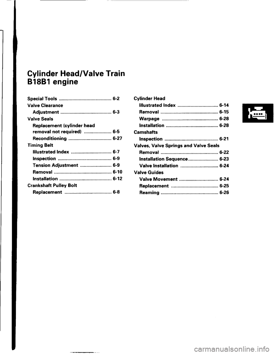
Cylinder Head/Valve Train
81881 engine
Speciaf Tools .............6-2
Valve Clearance
Adiustment ............6-3
Valve Seals
Replacement (cylinder head
removal not required) ..................... 6-5
Reconditioning ......6-27
Timing gelt
lllustrated Index ............................... 6-7
Inspection .............. 6-9
Tension Adiustment ........................ 6-9
Removal .................6-10
Installation .............6-12
Crankshaft Pulley Bolt
Replacement .........6-8
Page 65 of 1413
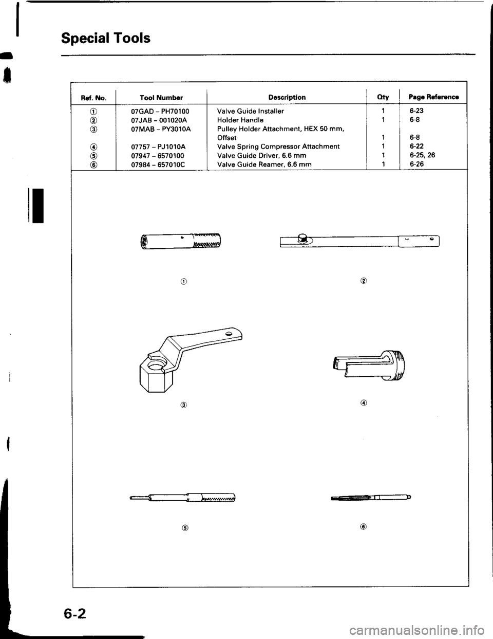
Special Tools
-
t
I
Ref. No. I Tool NumbrrOcacriptionOty I Prgc R.terencc
o
o
o
@
@
07GAD - PH70100
07JAB - 001020A
OTMAB _ PY3O1OA
07757 - PJ 10 toA
07947 - 6570100
07984 - 657010C
Valve Guide lnstaller
Holder Handle
Pulley Holder Attachment, HEX 50 mm,
Offset
Valve Spring Compressor Attachment
Valve Guide Driver, 6.6 mm
Valve Guide Reamer, 6,6 mm
1
1
1
1
1
1
6-8
6-8
6-22
6-25,26
6-26
o@
o
e:=-4-b4altltgtr-l-:ff:-b
@
Page 66 of 1413
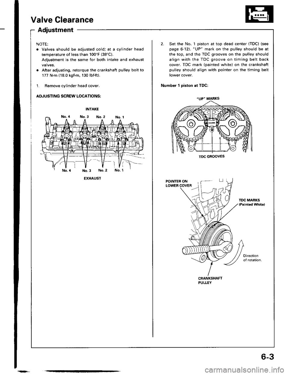
6-3
Valve Clearance
Adjustment
NOTE:
. Valves should be adjusted cold; at a cylinder head
temperature of less than 100'F (38"C).
Adjustment is the same for both intake and exhaust
valves.
. After adjusting, retorque the crankshaft pulley bolt to
177 N.m (18.0 kgim, 130 lbf.ft).
1. Remove cylinder head cover.
ADJUSTING SCREW LOCATIONS:
2. Set the No. 1 piston at top dead center (TDC) (see
page 6-12). "UP" mark on the pulley should be at
the top, and the TDC grooves on the pulley should
align with the TDC groove on timing belt back
cover. TDC mark (painted white) on the crankshaft
pulley should align with pointer on the timing belt
tower cover.
Number 1 Diston at TDC:
INTAKE
EXHAUST
TDC MARKSlPeinted whitel
CRANKSHAFTPULLEY
"UP" MARKS
TDC GROOVES
Page 67 of 1413
Valve Clearance
Adjustment lcont'dl
a
4.
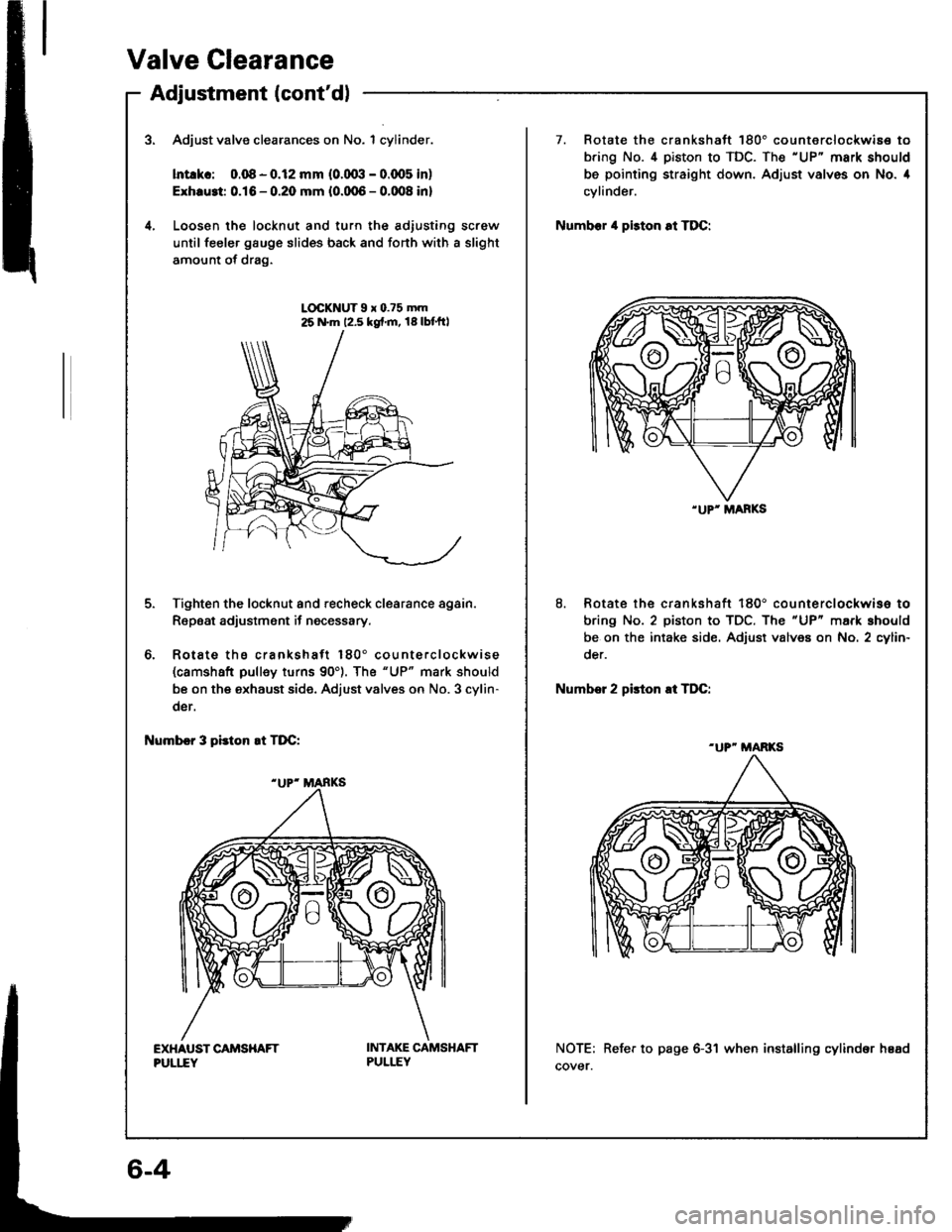
Adjust valve clearances on No. 1 cylinder.
lntlkc: 0.08 - o.l2 mm (o.(Xxl - 0.qr5 in)
Exhru3t 0.16 - 0.20 mm {0.0,05 - 0.008 in}
Loosen lhe locknut and turn the adjusting screw
until feeler gauge slides back and fonh with a slight
amount of drag.
LOCKNUT9x0.?5mm25 N.m 12,5 kgf.m, 18lbt'ft|
6.
Tighten the locknut and recheck clearance again.
Repeat adjustment if necessary.
Rotate ths crankshaft 180" counte.clockwise(camshaft pulley turns 90'). The "UP" mark should
be on the exhaust side. Adjust valves on No. 3 cylin-
der.
I{umbcr 3 pidon !t TDC:
EXHAUST CAITISHAFTPULI,IY
INTAKE CAMSHAFTPULLEY
.UP' MANKS
7. Rotate the crankshaft 180'counterclockwis€ to
bring No. 4 piston to TDC. The'UP" mark should
be pointing straight down. Adjust valves on No. 4
cylinder.
Numb€r il piston at TDC:
8. Rotate the crankshaft 180' co u nie rclockwise to
bring No. 2 piston to TDC. The "UP" mark should
be on the intake side. Adjust valves on No. 2 cylin-
oer.
Numbor 2 pirton !t TDC:
NOTE: Refer to page 6-31 when installing cylindor hEEd
cover.
"UP'MARKS
-UP" MARKS
Page 68 of 1413
Valve Seals
Replacement (cylinder head removal not requiredl
NOTE: Cylinder head removal is not required in this
procedure.
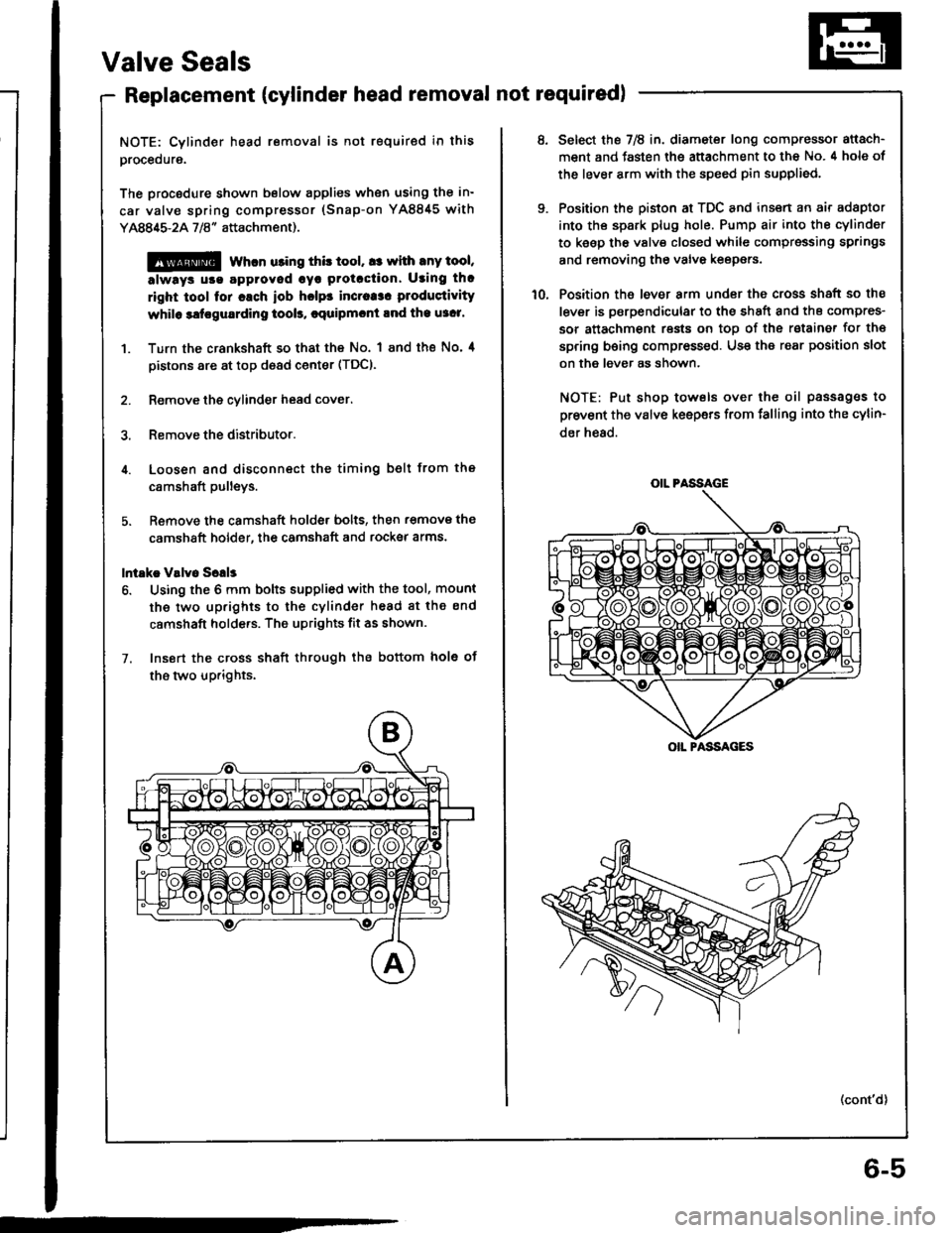
The procodure shown below applies when using the in-
car valve spring compressor (Snap-on YA8845 with
Y AAA$-2A 718" attachment).
@@ whcn u3ing this tool, a: with any tool,
always u!€ agproved cyr Protcction. Using th.
right tool for cach iob hclps incraa3. produstivity
whilo 3ltrgu8rding tool!, cquipmcnt lnd the u3c1'
1. Turn the crankshaft so that the No. I and the No' 4
pistons are at top d€ad center (TDC).
2. Remove the cylinder head cover.
3. Remove the distributor.
4. Loosen and disconnect the timing belt from the
c8mshaft pulleys.
5. Remove the camshaft holde, bolts, then r€move the
camshaft holder, the camshaft and rocksr arms.
lntakc V!lv6 Sclls
6. Using the 6 mm bolts supplied with the tool, mount
the two up.ights to the cylinder head 8t the end
camshaft holde.s. The uprights fit as shown.
7. Insort the cross shaft through the bottom hole ot
the two up.ights.
6-5
OIL PASSAGE
OIL PASSAGES
Select the 7E in. diameter long compressor attach-
ment and fasten the attachment to the No. 4 hole of
the lever arm with the speed pin supplied.
Position the piston at TDC and insert an air adaptor
into th€ spark plug hole. Pump air into the cylinder
to keep the valv€ closed while cgmpressing springs
and removing the valve keepers.
Position the lever arm under the cross shaft so the
lever is psrpendicular to the shEft and ths compres-
sor attachment rests on toD of the rstainer for th€
spring being compressed. Use the rear position slot
on the lever as shown.
NOTE: Put shop towels over the oil passag€s to
prevent the valve keepers from falling into the cylin-
der h€ad.
(cont'd)
Page 69 of 1413
-
'14.
Valve Seals
Replacement (cylinder head removal not required) (cont'dl
'11.Using a downward motion on the lever arm. com-press the valve spring and remove the keepers from
the valve stem. Slowly release pressure on the
spring.
Repeat step l1 for the other valve in that cylinder.
Remove the valve seals (see page 6-22).
Installthe valve seals (see page 6-23).
Install the springs, the retainers and the keepers in
reverse order of removal.
16. Repeat steps 9 to l5 for the other three cylinders.
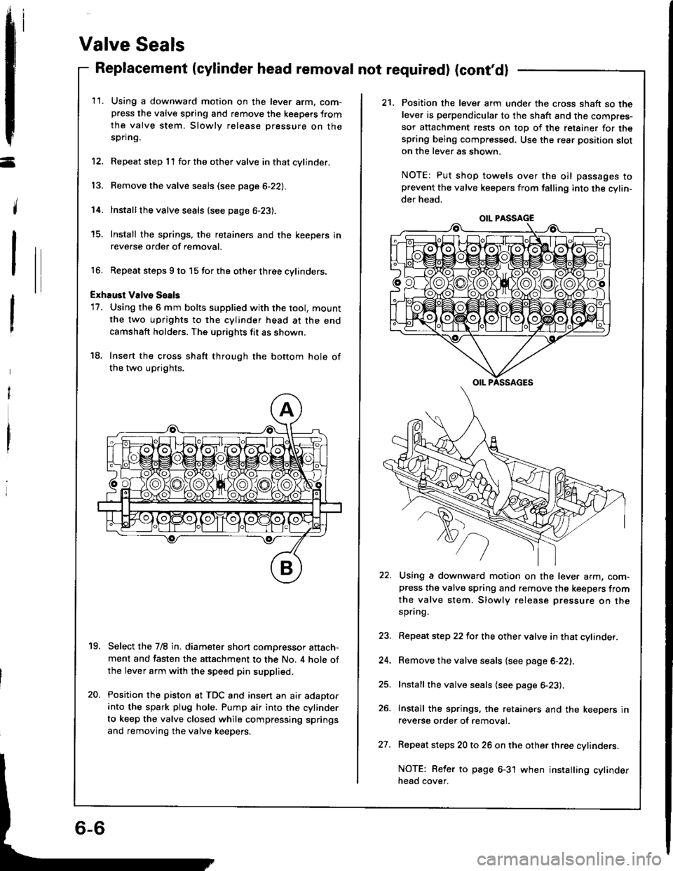
ExhaGt Valvs Soals
17. Using the 6 mm bolts supplied with the tool, mount
the two uprights to the cylinder head at the end
camshaft holders. The uprights fit as shown.
18. Insert the cross shaft through the bottom hole of
the two uprights.
Select the 7/8 in. diameter short compressor attach-ment and fasten the attachment to the No. 4 hole ofthe lever arm with the speed pin supplied.
Position the piston at TDC and insert an air adaptorinto the spark plug hole. Pump air into the cylinder
to keep the valve closed while compressing springs
and removing the valve keepers.
19.
20.
21. Position the lever arm unde. the cross shaft so thelever is perpendicular to the shaft and the compres-
sor attachment rests on top of the retainer for thespring being compressed. Use the rear position sloton the lever as shown.
NOTE: Put shop towels over the oil passages toprevent the valve keepers from falling into the cylin-der head.
Using a downward motion on the lever arm, com-press the valve spring and remove the keepers fromthe valve stem. Slowly release pressure on thespring.
Repeat step 22 for the other valve in that cylinder.
Remove the valve seals (see page 6-22).
Install the valve seals (see page 6-23).
Install the springs, the retainers and the keepers inreverse order of removal.
Repeat steps 20 to 26 on the other three cylinders.
NOTE: Reler to page 6-31 when installing cylinderneao cover.
OIL PASSAGE
27.
Page 70 of 1413
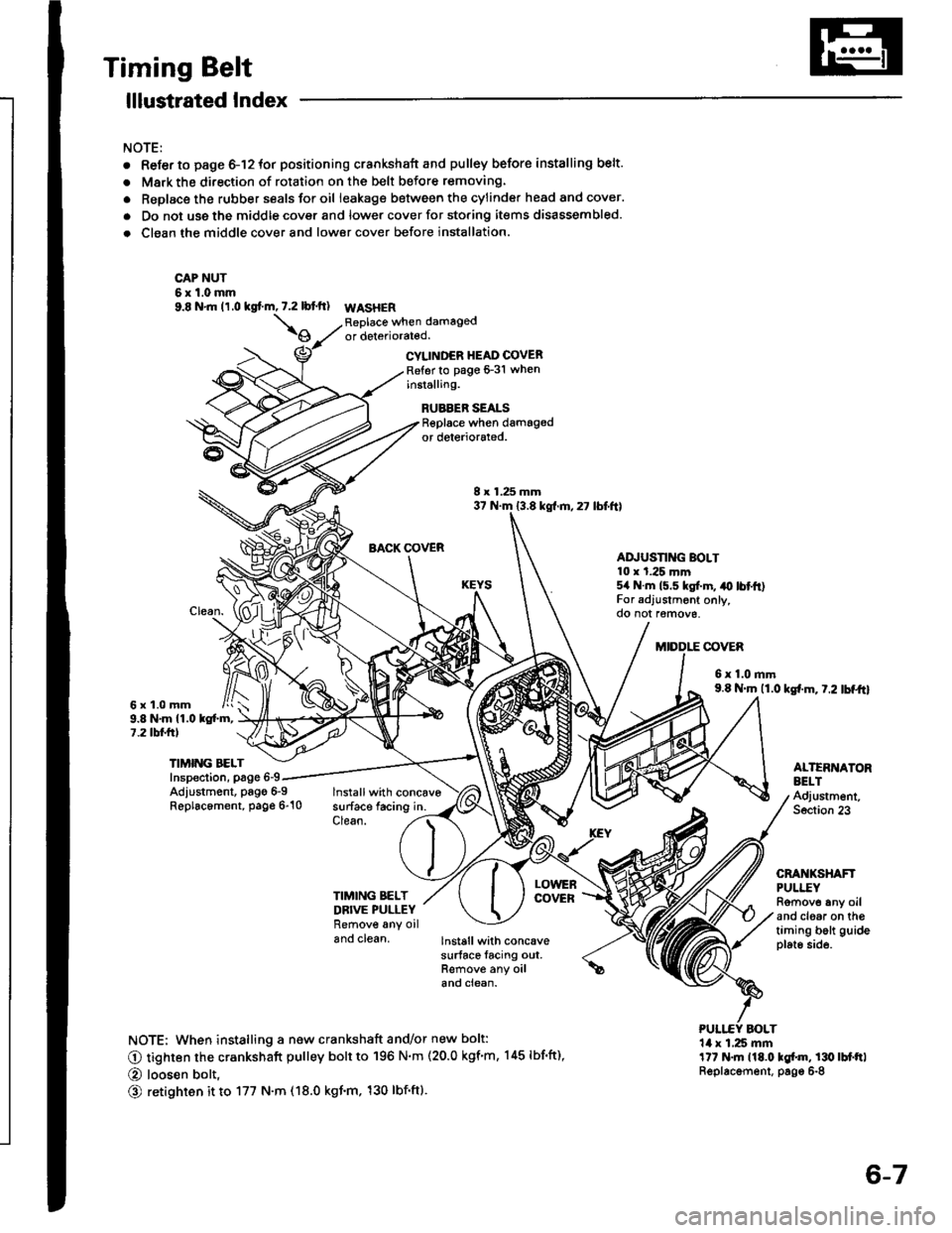
Timing Belt
lllustrated Index
NOTE:
. Refer to page 6-12 for positioning crankshaft and pulley before installing belt.
. Mark the direction of rotation on the belt before removing.
. Replace the rubber seals tor oil leakag€ between the cylinder head and cover.
a Do not uss the middle cover and lower cover for storing itsms disassembled.
. Clean the middle cover and lower cover before installation.
CAP NUT6xl.0mm9.8 N'm (1.0 kgf.m,7.2lbtft) WASHER
\oReplaco when damagedor deteriorated.
6x1.0mm
CYLINDER HEAD COVERRefer to pago 6-31 wheninstalling.
RUBBER SEALSReplace when damagedor deleriorsled.
BACK OOVER
lnstallwith concavesurface facing in.Clean.
8 x 1.25 mm37 N.m 13.8 kgl.m,27 lbf'ft)
AD.'USTING BOLT10 x t.25 mm5/r N.m 15.5 kgl.m, ,o lbtft)For adjustrnent only,do not r€move,
BOLT
COVER
6x1.0mm9.8 N'm (1.0 kg{.m. t.2 lbf.tt}
9.8 N,m 11.0 kg{.m,7.2 lbl.frl
Adlustment, pago 6-9Replacement, page 6"10
TIMIMi BELTInspection, page 6-9ALTERNATORBELTAdjustm6nt,Soction 23
CRANKSHAFTPULI"EYRomov6 any oiland clgaa on thgtiming bolt guideplato side.
TIMING BELTDBIVE PULLEYRemove any oiland clean,
LOWEnCOVER
lnstall with concavesurface facing out,Remove any oilano ctean.
NOTE: When installing a new crankshaft and/or new bolt:
O tighten the crankshaft pulley bolt to 196 N'm (20.0 kgf'm, 145 lbf'ft),
O loosen bolt,
O retighten it to 177 N.m (18.0 kgt.m, 130 lbf'ftl.
'14 x 1,25 mmlt7 t{.m 118.0 kgl.m, 130lbtftlReplacsmenl, page 6-8
6-7