HONDA INTEGRA 1994 4.G Manual Online
Manufacturer: HONDA, Model Year: 1994, Model line: INTEGRA, Model: HONDA INTEGRA 1994 4.GPages: 1413, PDF Size: 37.94 MB
Page 81 of 1413
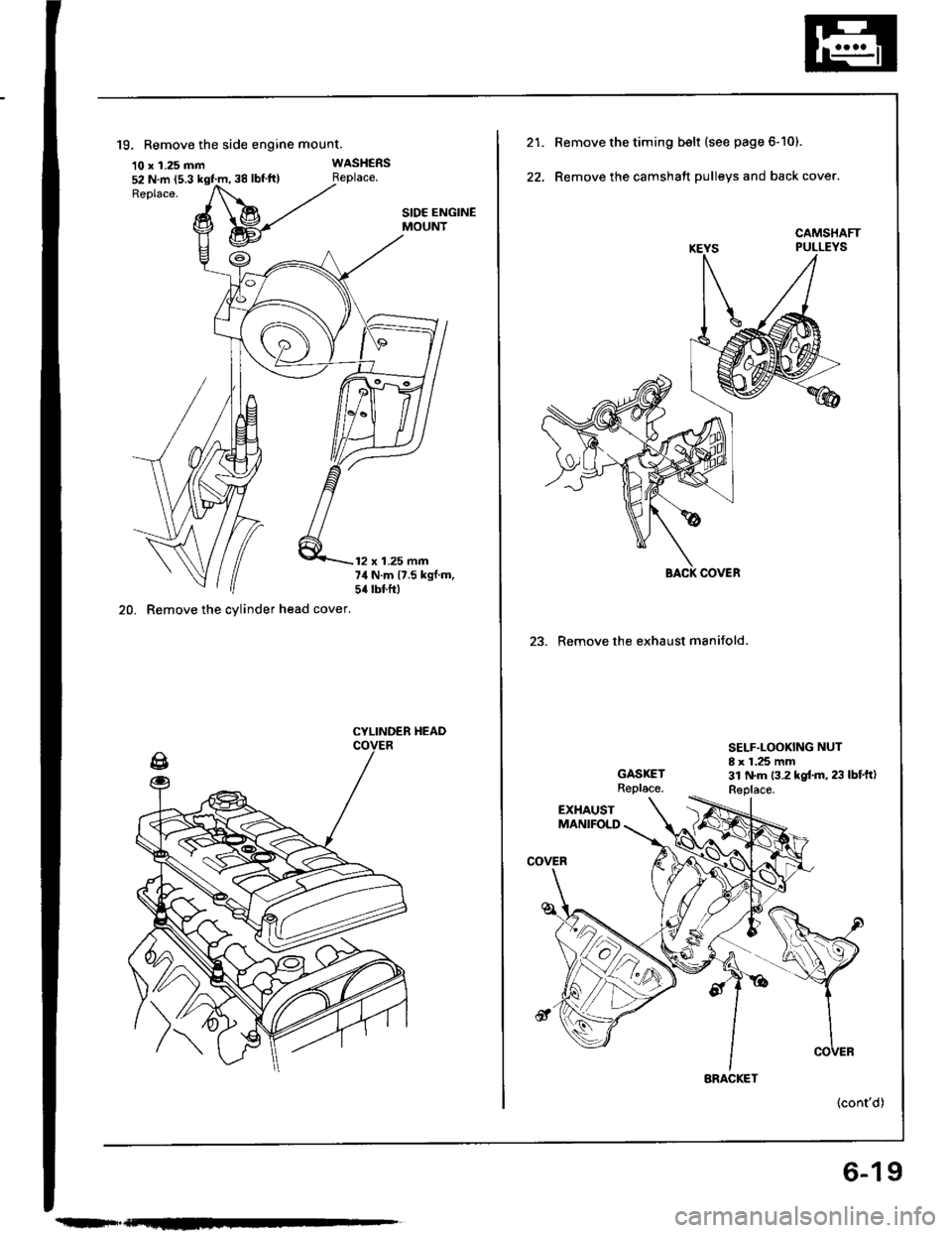
52 N.m (5.3 kgt'm, 38 lbf'ft)
19. Remove the side engine mount.
10 x 1.25 mm
20. Remove the cylinder head cover.
WASHERS
SIDE ENGINEMOUNT
12 x 1.25 mm74 N.m {7.5 kgf.m,5{ rbtftl
CYLINDEB HEAD
Remove the timing belt (see page 6-10).
Remove the camshaft pulleys and back cover.
23. Remove the exhaust manifold.
SELF.LOOKING NUT8 x 1.25 mm
BACK COVER
BRACKET
(cont'd)
6-19
Page 82 of 1413
Cylinder
Removal
Head
(cont'dl
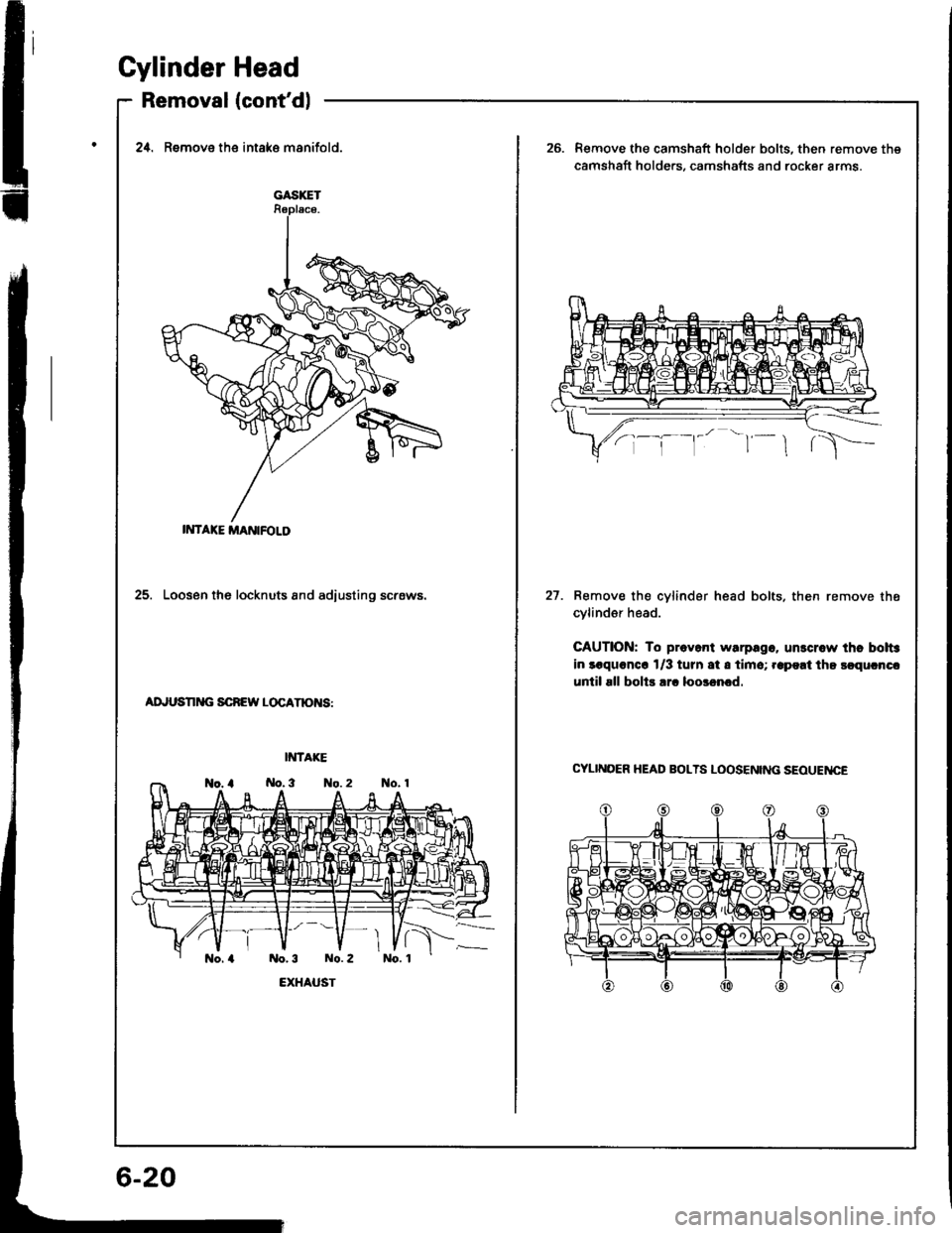
GASXET
IMTAXE MANIFOLD
2,0. Remove the intake msnifold.Remove the camshaft holder bolts, then remove the
camshaft holde.s. camshafts and rocker arms.
25. Loosen the locknuts and adiusting screws.27. Remove the cylinder head bolts. then remove the
cvlindsr head.
CAUTION: To preyant warpago. unlcr.w thc bolt3
in laquoncc 1/3 turn at I tim6; .apeat the $qurnca
until sll boltr arc loosrncd.
ADJUSNNG SCNEW LOCATN)NS:
CYLINOER HEAD BOLTS LOOSENING SEOUENCE
Page 83 of 1413
!
1.
2.
Camshafts
Inspection
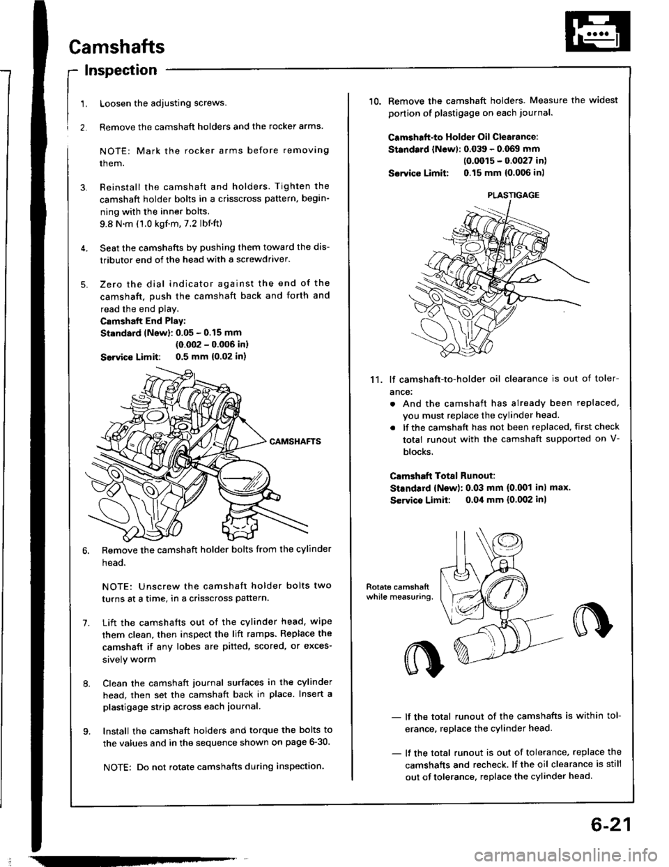
Loosen the adjusting screws.
Remove the camshaft holders and the rocker arms
NOTE: Mark the rocker arms before removing
them.
Reinstall the camshaft and holders. Tighten the
camshaft holder bolts in a crisscross pattern, begin-
ning with the inner bolts.
9.8 N.m (1.0 kgf.m,7.2 lbf.ft)
Seat the camshafts by pushing them toward the dis-
tributor end of the head with a screwdriver.
Zero the dial indicator against the end of the
camshaft. push the camshaft back and forth and
read the end play.
Camshalt End Play:
St.ndard lNow): 0.05 - 0.15 mm
(0.002 - 0.006 inl
Seivice Limit: 0.5 mm {0,02 in)
Remove the camshaft holder bolts from the cylinder
head.
NOTE: Unscrew the camshaft holder bolts two
turns at a time, in a crisscross pattern.
Lift the camshafts out ot the cylinder head. wipe
them clean, then inspect the lift ramps. Replace the
camshaft if any lobes are pitted, scored, or exces-
srvely worm
Clean the camshaft journal surfaces in the cylinder
head, then set the camshaft back in place. Insert a
plastigage strip across each iournal.
Install the camshaft holders and torque the bolts to
the values and in the sequence shown on page 6-30.
NOTE: Do not rotate camshafts during inspection.
-
6-21
10.Remove the camshaft holders. Measure the widest
ponion of plastigage on each journa..
Camshaft-to Holder Oil Clearance:
Standard lNewl: 0.039 - 0.069 mm(0.0015 - 0.0027 in)
Sarvico Limit 0.15 mm {0.006 inl
11. lf camshaft-to-holder oil clearance is out of toler
ance:
. And the camshaft has already been replaced,
vou must replace the cylinder head.
. lf the camshaft has not been replaced, first check
total runout with the camshaft supported on V-
blocks.
Clmshaft Total Runout:
StEndard {New): 0.03 mm (0.001 inl max'
Servico Limit: o.Oil mm {0.002 inl
- lf the total runout of the camshafts is within tol-
erance, replace the cylinder head.
- lf the total runout is out of tolerance, replace the
camshafts and recheck. lf the oil clearance is still
out of tolerance. replace the cylinder head.
PLASTIGAGE
Page 84 of 1413
Valves, Valve Springs and Valve Seals
Removal
1.
2.
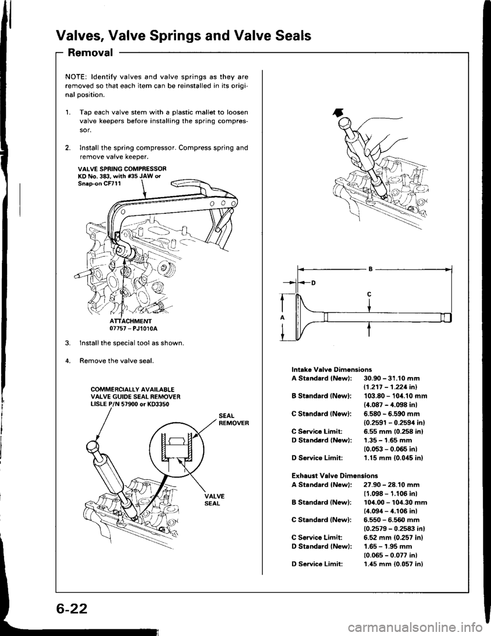
NOTE: ldentify valves and valve springs as they are
removed so that each item can be reinstalled in its oriqi-
nal Dosition.
Tap each valve stem with a plastic mallet to loosen
valve keepers before installing the spring compres-
sor.
lnstall the spring compressor. Compress spring and
remove vatve Keeper.
07757 - PJ10r0A
Installthe special tool as shown.
Remove the valve seal.
COMMERCIALLY AVAILABLEVALVE GUIDE SEAL REMOVERLISLE P/N 5t9d) or KO3350
SEALREMOVER
VALVE SPRING COMPRESSORxo No.3tB. whh r35 JAW o.
lntaks Valvo Dimonsions
A Standard (New): 30.90 - 31.10 mm
|.1.217 - 1.221inl
I Standard (Nowl: 103.80 - 10'1.10 mm
{4.087 - 4.098 inl
C Standard lNow): 6.580 - 6.590 mm
{0.2591 - 0.259/r in}
C Servico Limit 6.55 mm (0.258 inl
D Standlrd (N€w): 1.35 - 1.65 mm
10.053 - 0.065 inl
D Ssrvice Limit: 1.15 mm (0.045 in)
Exhau3t Valve Dim6nsions
A Standard {New): 27.90 - 28.10 mm
11.098 - 1.106 inl
B Standard (Newl: 104.00 - 104.30 mm(4.094 - 4.106 inl
C St.ndard (New): 6.550 - 6.500 mm
10.2579 - 0.2583 inl
C Servico Limit 6.52 mm (0.257 in)
D Standard {New): 1.65 - 1.95 mm
10.065 - 0.077 inl
D Service Limit: 1.,[5 mm (0.057 in)
Page 85 of 1413
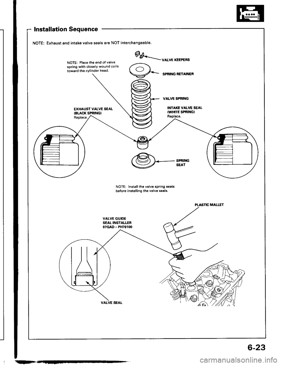
Installation Sequence
NOTE: Exhaust and intake valve seals ate NOT interchangeable.
NOTE: Place th€ 6nd oI valve
spring with closelY wound coils
towrrd th€ cylinder head.
EXHAUST VALVE SEAL{8LACK SPRING}Replace.
NOTE: Installth€ v6lvo spring s€atsbeforo instslling the valv6 sesls.
@/.-uo.**.r..",
SPRNG NETAINER
@*_-.tt*
PLASTIC MALIIT
.tIF"F-
6-23
Page 86 of 1413
Valves, Valve Springs and
Valve Seals
Valve lnstallation
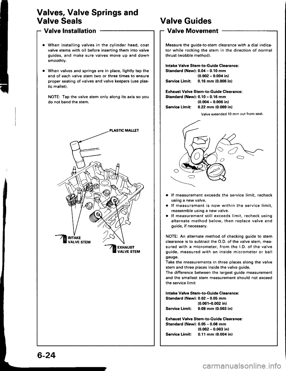
When instaliing valves in the cylinder head, coat
valve stems with oil before insening them into valve
guides, and make sure valves move up and down
smoothlv.
When valves and springs are in place, lightly tap the
end of each valve stem two or three times to snsure
proper seating of valves and valve keepsrs (use plas-
tic mallet).
NOTE: Tap the valve stem only along its axis so you
do not bend the stem.
PLASNC MALI.IT
?ur
Valve Guides
Valve Movement
Measure the guide-to-stem clearance with a dial indica-
tor while rocking the stem in the direction of normal
thrust (wobble method).
lntake Valve Stsm-to-Guide Clearance:
Strndlrd (Newl: 0.0i1- 0.10 mm
(0.002 - 0.004 in)
Ssrvicc Limit: 0.16 mm {0.006 in)
Exhsust Valye Stom-to-Guide Clearance:
Standard {N€w): 0.10 - 0.16 mm
{0.0O'l - 0.006 in)
Slrvica Limit: 0.22 mm {0.000 in)
Valve extended 10 mm out from seat
lf measurement exceeds the service limit, recheck
using a new valve.
lf measurement is now within the service limit,
reassemble using a n€w valve.
lf measurement still exceeds limit, recheck using
alternate method below. then replace valve and
guide, if necessary.
NOTE: An alternate method of checking guide to stem
clearance is to subtract the O.D. of the valve stem, mea-
sured with a micrometer. from the l.D. of the valve
guide, measured with an inside micrometer or ball
gauge.
Take the measurements in three places along the valve
stem and three places inside the valve guide.
The diiference between the largest guide measurement
and the smallest stem measurement should not exceed
the service limit
lntake Valve Stom-to-Guide Clearance:
Standard (Newl: 0.02 - 0.05 mm(0.001-0.002 in)
Service Limit 0.08 mm (0.003 in)
Exhaust Valve Stom.to.Guid€ Clearanco:
Standard (Newl: 0.05 - 0.08 mm(0.002 - 0.003 inl
Srrvico Limit 0.ll mm 10.00't inl
6-24
Page 87 of 1413
I
Replacement
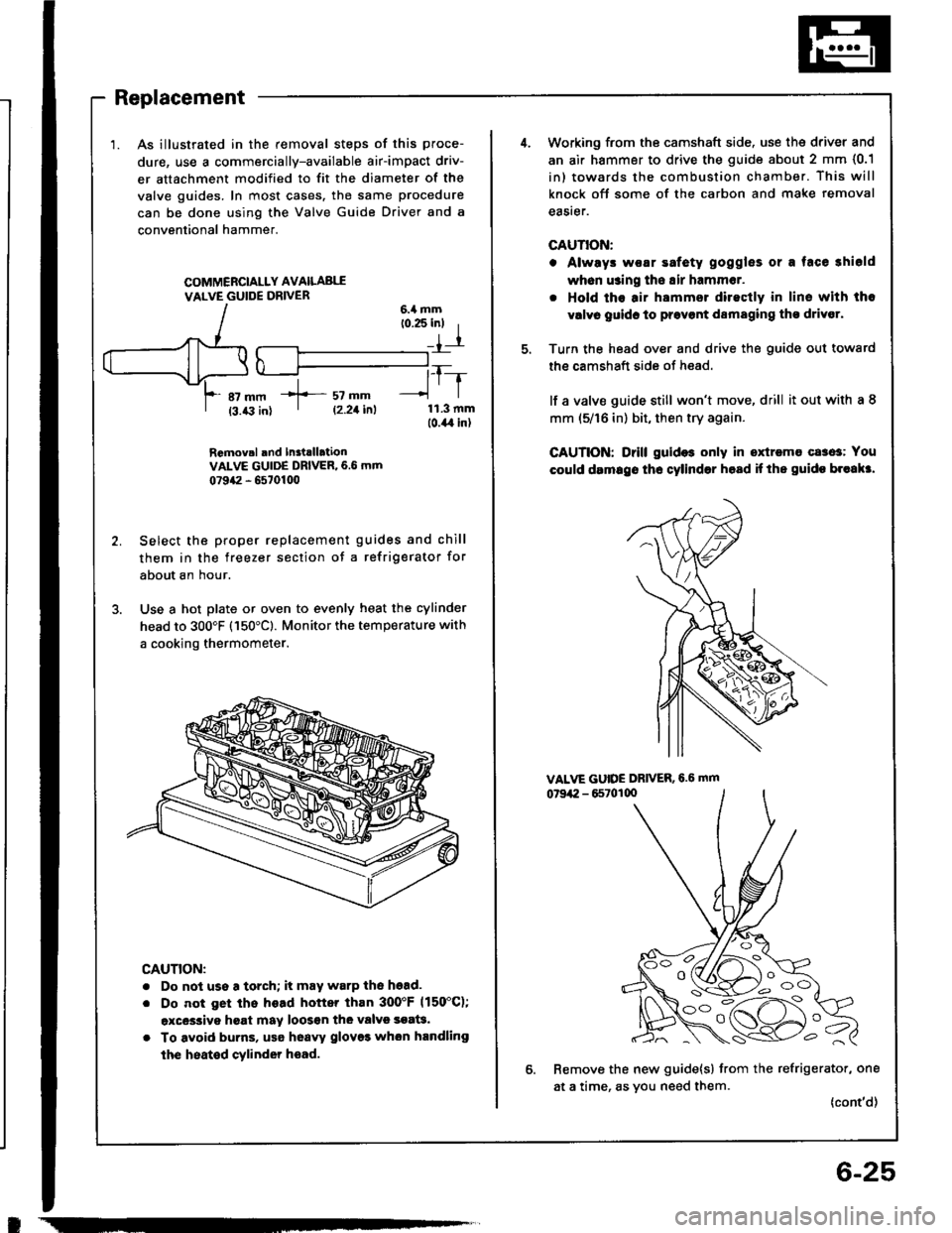
1. As illustrated in the removal steps of this proce-
dure, use a commercially-available air-impact driv-
er attachment modified to fit the diameter of the
valve guides. In most cases. tho same procedure
can be done using the Valve Guide Driver and a
conventional hammer.
COMMERCIALLY AVAILABI,I
VALVE GUIDE DRIVER
RGmov.l rnd In3tlllationVALVE GUIDE DRIVER, 6.6 mm
0?942 - 6570100
Select the proper replacement guides and chill
them in the freezer section of a refrigerator for
about an hour.
Use a hot plate or oven to evenly heat the cylinder
head to 300'F (150'Cl. Monitor the temperature with
a cooking thermometer.
CAUTION:
. Do not use a torch; it may warP the hgad.
. Do not get ths head hottq than 3OO'F 1150"C);
excessive hgat may loos€n thG valvs soat3.
. To avoid burns, usa hoavy glov93 whon handling
the heated cylinder hoad.
-----T_-
lrl
11.3 mmlo.il,l in)
f sz --| 12.21i^l
6-25
4.Working from the camshaft side. use the driver and
an air hammer to drive the guide about 2 mm {0.1
in) towards the combustion chamber. This will
knock oft some of the carbon and make removal
eaSrer.
GAUTIOiI:
o Alwrys woar safety goggles or a face shiold
wh6n using tho Eir hammer.
. Hold ths air hammsr directly in lins with the
vrlvr guidc to prsvont damaging tho drivor.
Turn the head over and drive the guide out towatd
the camshaft side of head.
lf a valve guide still won't move, drill it out with a 8
mm (5/16 in) bit, then try again.
CAUTION: Drill guid$ only in oxtremo cases: You
could drmrgo tho cylinder hosd if ths guido br"akr.
VALVE GUIDE DRIVER,6.6 mm
07942 - 65701q)
Remove the new guide{s} from the refrigerator, one
at a time, as you need them.
{cont'd)
OO ",
O (V /rl -1-- ) o
Page 88 of 1413
Valve Guides
Replacement {cont'd}
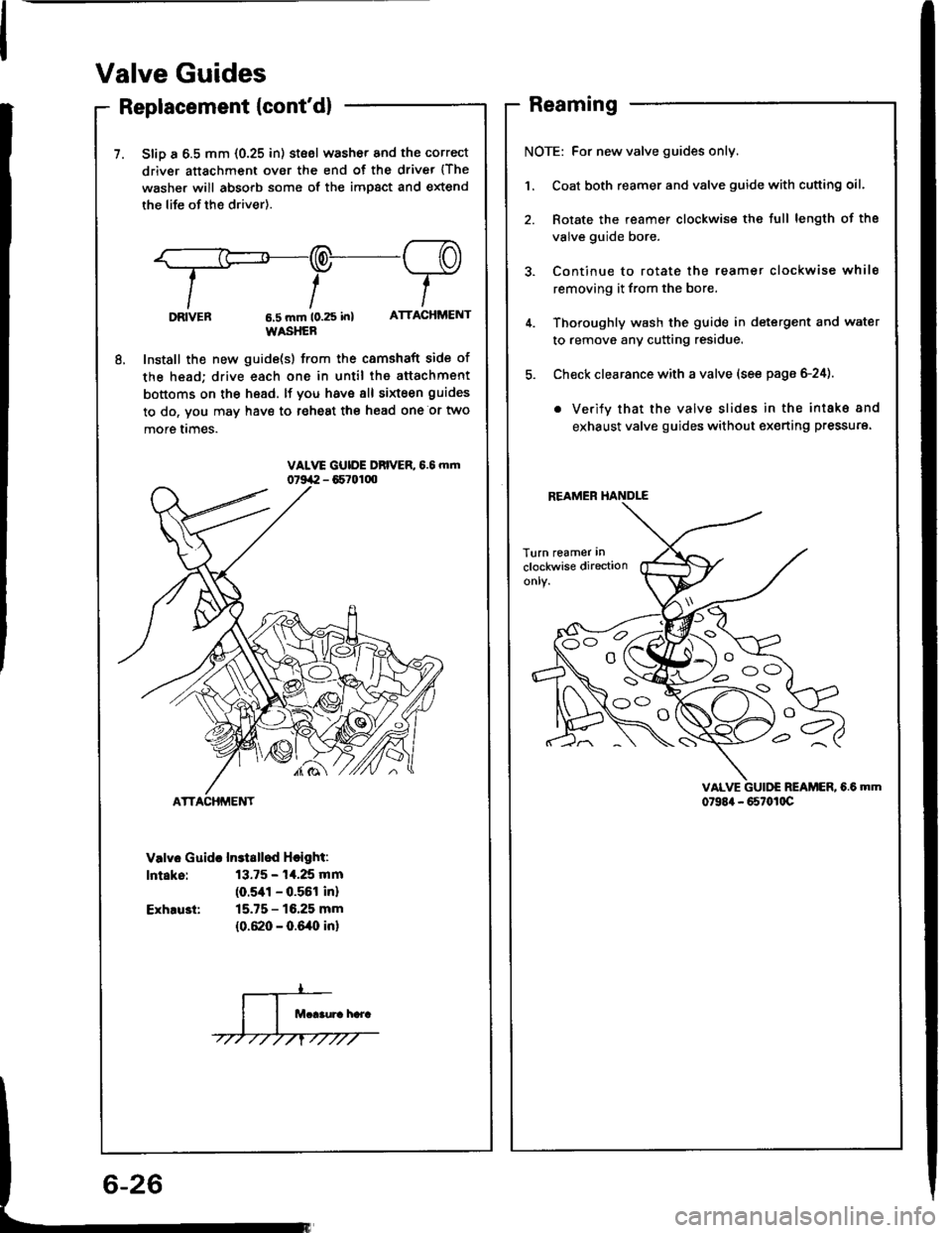
7. SliD a 6.5 mm {0.25 in) stsel washor and the correct
driver attachment over the end of the driver {The
washer will absorb some of the impact and extend
the life of the driver).
.,F-q-re
tt-T-IIttlDRVEn 6,5 mm t0.25 in) ATTACHMENT
WASHER
8, Install the new guide(s) from the camshaft side of
the head; drive each one in until the attachment
bottoms on the head. lf you have 8ll sixteen guides
to do, vou may have to reheat the head one or two
more I|mes.
Valv6 Guida Instsllod Hcight:
lntaks: 13.75 - 14.25 mm
(o.sal - 0.561 inl
Exhru3t: 15.75 - 16.25 mm
{0.620 - 0.640 in}
Reaming
NOTE: For new valve guides only.
Coat both reamer and valve guide with cutting oil.
Rotate the reamer clockwise the full length of the
valve guide bore.
Continue to rotate the reamet clockwise while
removing it from the bore.
Thoroughly wash the guide in detergent and water
to remove any cutting residue.
Check clearance with a valve (see page 6-24).
. Verify that the valve slides in the intake 8nd
exhaust valve guides without ex€rting pressure.
VALVE GUII'E REAMER, 6.6 MM
079E4 - 667ot0c
REAMER HANDLE
s
Page 89 of 1413
Valve Seats
ACTUALSEATINGSUBFACE
VALVESEAT
PRUSSIAN
Reconditioning
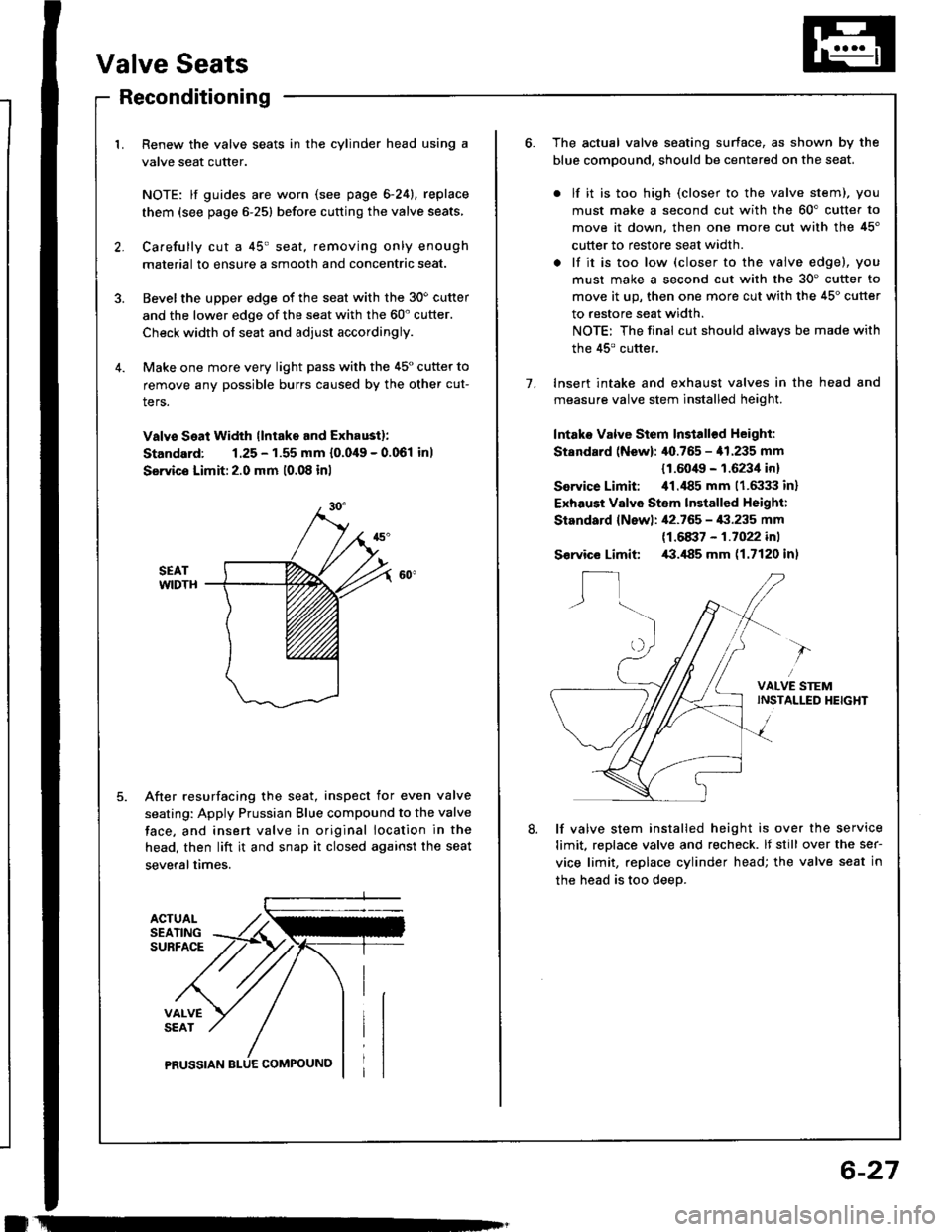
1. Renew the valve seats in the cylinder head using a
valve seat cutter.
NOTE: lf guides are worn (see page 6-24), replace
them (see page 6-251 before cutting the valve seats,
2. Carefully cut a 45' seat, removing only enough
material to ensure a smooth and concentric seat.
3. Bevel the upper edge of the seat with the 30o cutter
and the lower edge of the seat with the 60' cutter.
Check width of seat and adjust accordingly.
4. Make one more very light pass with the 45" cutter to
remove any possible burrs caused by the other cut-
ters.
Valvo Seat Width llntake and Exhaustl:
Standard: 1.25 - 1.55 mm {0.049 - 0.061 inl
Servics Limit:2.0 mm 10.08 inl
SEATWIDTH
After resurfacing the seat, inspect for even valve
seating: Apply Prussian Blue compound to the valve
face, and insert valve in original location in the
head, then lift it and snap it closed against the seat
severaltimes.
!
6-27
7.
The actual valve seating surface, as shown by the
blue compound, should be centered on the seat.
. lf it is too high (closer to the valve stem), you
must make a second cut with the 60" cutter to
move it down, then one more cut with the 45'
cutter to restore seat width.
. lf it is too low (closer to the valve edgel, you
must make a second cut with the 30' cutter to
move it up, then one more cut with the 45" cutter
to restore seat width.
NOTE: The final cut should always be made with
the 45' cutter.
Insert intake and exhaust valves in the head and
measure valve stem installed height
Intako Valve Stem Install€d Height:
Standard (New): /$.765 - '11.235 mm
{1.604It - 1.6234 in}
Service Limit: ill.il85 mm (1.6:133 inl
Exhaust Valvo Stem lnstalled Height:
Standard {Newl: ,12.765 - i|:|.235 mm
11.6a37 - 1.1022 in1
Service Limit /B.il85 mm (1.7120 inl
lf valve stem installed height is over the service
limit, reDlace valve and recheck. lf still over the ser-
vice limit, replace cylinder head; the valve seat in
the head is too deeo.
8.
Page 90 of 1413
t
Gylinder Head
Installation
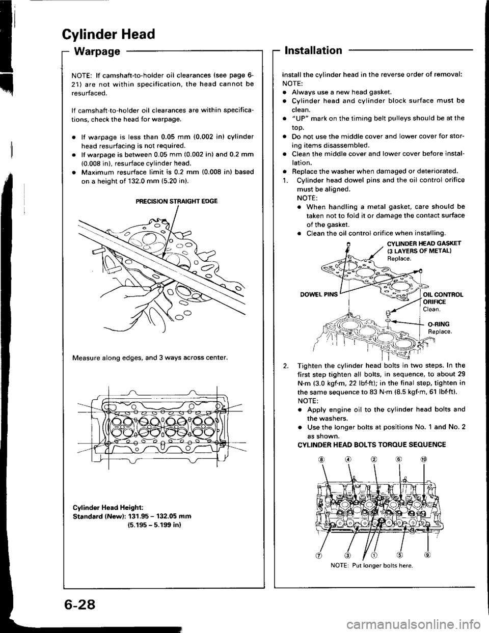
Installthe cylinder head in the reverse order of removal:
NOTE:
. Always use a new head gasket.
. Cylinder head and cylinder block surface must be
ctean.
. "UP" mark on the timing belt pulleys should be at the
top.
. Do not use the middle cover and lower cover for stor-
ing items disassembled.
. Clean the middle cover and lower cover before instal-
lation.
. Replace the washer when damaged or deteriorated.'1. Cylinder head dowel pins and the oil control orifice
must be aligned,
NOTE:
. When handling a metal gasket, care should be
taken not to told it or damage the contact surface
of the gasket.
. Clean the oil control orifice when installing.
CYLINDER HEAD GASKET
{3 LAYERS OF METALIReplace.
OOWEL PINSorl coNtnolORIFICEClean.
O.RINGReplace.
Tighten the cylinder head bolts in two steps. In the
Jirst step tighten all bolts, in sequence, to about 29
N.m {3.0 kgf.m, 22 lbl.ltJ; in the final step, tighten in
the same sequence to 83 N.m (8.5 kgf.m, 61 lbf'ft).
NOTE:
. Apply engine oil to the cylinder head bolts and
the washers.
. Use the longer bolts at positions No. 1 and No. 2
as shown.
CYLINDER HEAD BOLTS TOROUE SEOUENCE
@o@@@
NOTE: lf camshaft-to-holder oil clearances (see page 6-
21) are not within specitication, the head cannot be
resurfaced.
lf camshaft'to-holder oil clearances are within specifica-
tions, check the head for warpage.
lf warpage is less than 0.05 mm (0.002 in) cylinder
head resurtacing is not required.
lf warpage is between 0.05 mm (0.002 in) and 0.2 mm
(0.008 in), resurface cylinder head.
Maximum resurface limit is 0.2 mm (0.008 in) based
on a height of 132.0 mm (5.20 in).
Measure along edges, and 3 ways across center.
Cylinder Hoad Height:
Standard (New): 131.95 - 132.05 mm
{5.195 - 5.191t in}
PRECISION STRAIGHT EOGE
Put longer bolts here.