HONDA INTEGRA 1994 4.G Service Manual
INTEGRA 1994 4.G
HONDA
HONDA
https://www.carmanualsonline.info/img/13/6067/w960_6067-0.png
HONDA INTEGRA 1994 4.G Service Manual
Trending: Dashboard wire harness, hose, air conditioning, tire type, Fuel pump relay, differential, oil type
Page 41 of 1413
@
,6\
a,\
@
o@
@
@
o
@
@
@
4-3
\.___ _
Page 42 of 1413
Maintenance Schedule
r.r r l{H F*
z
=
338
scE-ts.8
.969
.96;!
-:=i
3.es96i
.g6
?o
;:x
;;;;
ci cj
8888OOEte
-q-.!E
rttlE
; t:9;!'.!srn=
-F
9;5b
E69!
iE
t93
tEi3 aas
!gt; >9
?;P
3 H:
".8
F!
Ep:;
Pti-EEbE
3 E;
ia!E5;!!
;Ei*E9EE
i;
9H";
:=33*xA.it>11
4+!?9-zc;c;.... : :
-o E E
d(,--
EEoN
ii ii x(,(9 6-zz0
6
P
'i
=
];;
Poa
Eqn
8oo8"j n
-=
SE
Fit9*-
=z
dE
I9
l3t6
IPIE
lr.
::
e
6
9
gE
q
6I
.s
a
,9
E
FE
E
E
EE
EE
EE
EE
E
EEI
EE
E
E
E..ll
:E
q
tl
EI
rl
.l
'!l
-9
D
2 | -ti
;t;
-l-
___l_
.t
o
i
oo
E
.E
=
tifl
lil
.g
I.9
:q !.EE €6F 5;i
rI ii:
EE ::Ec =96 9-a;
p3 F;E |i
a9 E.rb5e !
E 5_ c
;e:fii
irPt;
E iEF:=:6--:O!P9 E: oli o
E
*t
j:
o.9
-c5
.EP8::
Ee
.PE
a
I
!-
-9
g
I
4-4
Page 43 of 1413
E-.i a
2l,.ii
.49Po:.:
e66
.9
3
E
-9
-
!
F
.g
.9
.>
E
.9
.9a
.9
,8.
Eo,E
F:,!
E
+>
9E!6
9.t
ol
.
-9
-9
.
-9
E E; E:
-'."': !:;&6('+.9i:
€ E;; g;!
! E;3;: E':+d6d6-
s!i;:;g
E
t
E
E
E
6
-gE
Ea
;
4-5
Page 44 of 1413
Maintenance Schedule
*
8"i8dq60-t
I 6 .: d
i i:E ;
€EEEE
i E9i !
# i€i EF 5]T EE !.P; Pr Ei5 6
i"!;i*
EEFii'F
€;E?Bsii
iii;iiig
!;6 9:€;g
;+€ +fF; i
(9
f
aE.i
3si
!:-E
ZE
3ii
.;-
! i..i
i 3E g
i ;i:
I .+3 !
E i 3EE
ET E'"EE F
;E : iin;
E:i ::::i
a a: i,l --6- 6ig6i ::ElE€=.E! a : o e i c !.
6i.s !.fl .f FE€
E:E gE!EE;F
3 !.s Ft a d a,i.;
-
!
,
I
I
gpU6;f,
II
tt-
I
B
iI
tl
z
!i
€'
9€
it
{t
8s6]o5
P.: E
i;i
5:E
e
!
rE39 EE:31
EEE5+ !
99,?
6E
s!6:bi
99
35d'i
:!lca4
it;
\z
]
5
.9
a
o
IIE
E
,4
E
q
R
..6
a;iEdE
3
e
€
!ic.5.9 ,.F3
o*3
.=E
6Z.]
5
'i
p
i
4-6
Page 45 of 1413
Engine
Engine Removal/lnstallation ...''........ 5-1
Cylinder Head/Valve Train ..'............ 6-1
Engine Block ..........7-1
Engine Lubrication ......... 8-1
Intake Manifold/Exhaust System ...... 9-1
Cooling ....... 1O-1
Page 46 of 1413
Engine Removal/lnstallation
Special Tools ........ .".....5-2
Engine Removal/lnstallation ..."........ 5-3
Mount/Bracket Torque ..' 5-16
Page 47 of 1413
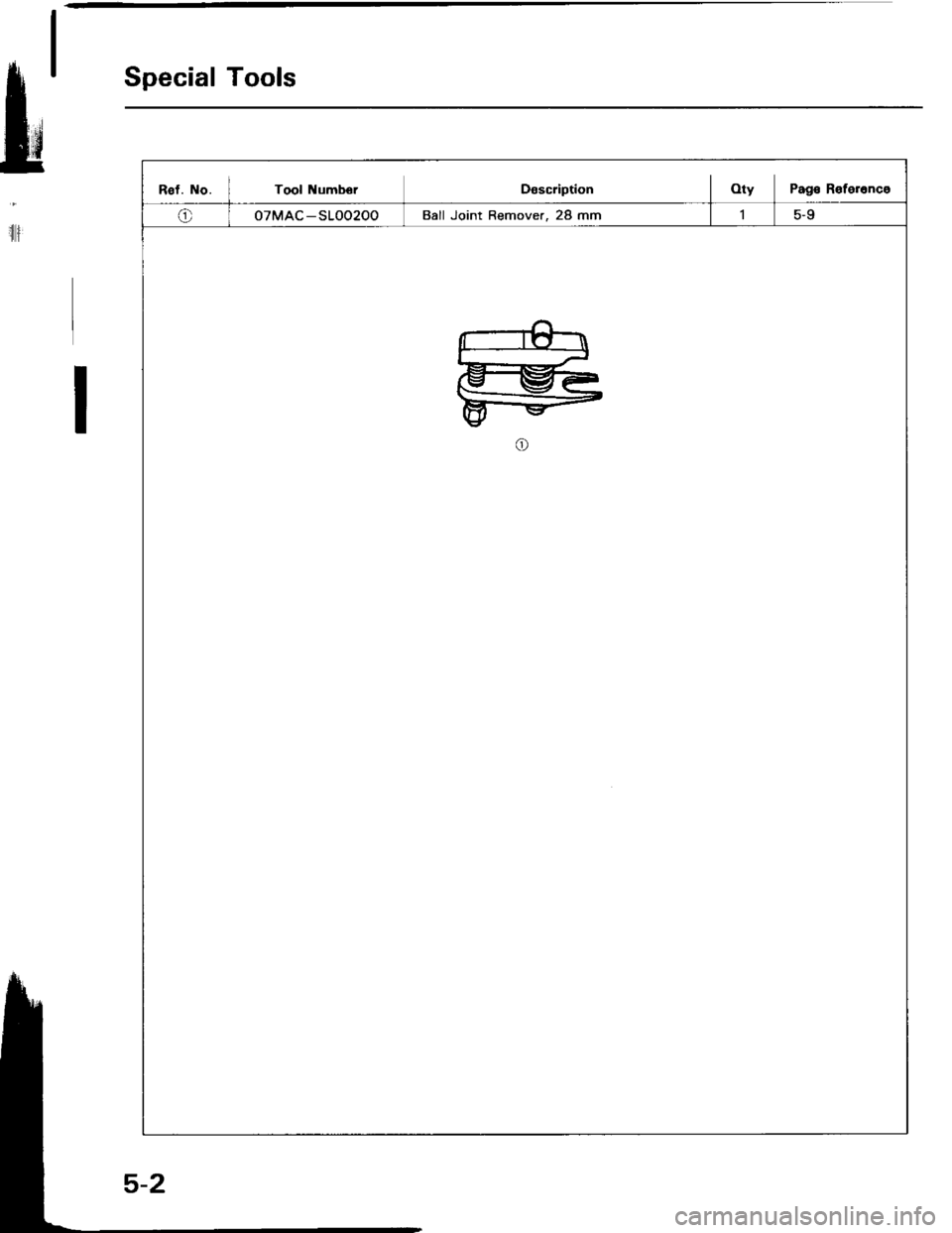
Special Tools
Rst. No. I Tool NumborDascriptionOty Pag€ R€terenco
o07MAC-SLOO200Ball Joint Remover, 28 mm
ru
il
Page 48 of 1413
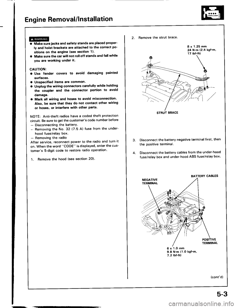
Engine Removal/lnstallation
@a Make sure jacks and safety stands aro placed ploper-
ly and hoisl brackots arg attachod to the correct po-
sitions on tho engine (se€ ssction 1).
a Mak€ sure tho car willnot roll off stands and tallwhile
you are wotking under it'
CAUTION:
a Use fendet covals to avoid damaging painted
sudaces.
r Unspecified itsms alo common
a Unplug tho widng connectots carefully while holding
the couplor and tha connector portion to avoid
oamage.
a Mark all wiring and hoses to avoid misconnection.
Also, be sulo that thsy do not contact other wiring
or hoses, or interfere with oth€l parts.
NOTE: Anti-theft radios have a coded theft ptotection
circuit. Be sure to get the customer's code number beJore
- Disconnecting the batterY.
- Removing the No. 32 (7.5 A) fuse from the under-
hood tuse/relay box.- Removing the radio
Atter service, reconnect power to the radio and turn it
on. When the word "CODE" is displayed, enter the cus-
tomer's 5-digit code to restore radio operataon.
1. Remove the hood (see section 2O).
2. Remove the strut brace
8 x 1.25 mm24 N.m (2.4 kgf.m,17 rbt.ft)
Disconnect the battery negative terminal lirst. then
the positive terminal.
Disconnect the battery cables from the undel-hood
fuse/relay box and under-hood ABS fuse/relay box.
6 x l.O mm9.8 N.m (1 .O kgf'm,7.2 rbl.ftl
{cont'd)
STRUT ERACE
BATTERY CABLES
5-3
Page 49 of 1413
Engine Removal/lnstallation
m
(cont'd)
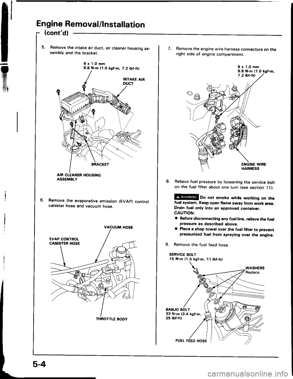
Remove the intake air duct, air cleaner housing as-semblv and the bracket.
6 x 1.O mm9.4 N.m {l.O ksf.m, 7.2 tbf,ftl
Remove the evaporative emission (EVAp) controlcanister hose and vacuum hose.
VACUUM HOSE
THROTTI.E BODY
7. Remove the engine wire harness connectoE on theright side of engine compartment.
8. Relieve fuel pressure by loosening the service bolton the tuel filter about one turn {see section 1 1).
@ oo not amoke whito working on thofuel system. Keep open flame away trom wo.k arsa.Drain fuel only into an approved container.CAUTION:
a Before disconnocting any fu€l line. reliovo the tuolpressule as doscribed above.a Place a shop towel ov61 the fu6l filter to prevontprossurized tuel from spraying ovel tho aogine.
9. Remove the fuel feed hose.
SERVICE BOLT15 N.m (1.5 kgt.m, 11 tbt.ftl
BAITJO EOLT33 N.m 13.4 kgt.m,25 tbt.ftt
6 x'l.O mm9.8 N-m ll.0 kgt.m.
Page 50 of 1413
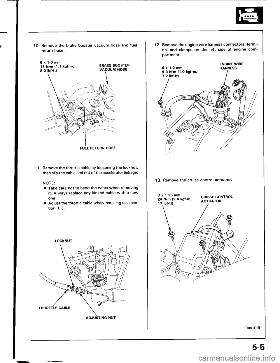
1O. Remove the brake booster vacuum hose and fuel
return hose.
6 x 1.O mm11 N.m {1.1 kgl'm,8.O rbt.ltl
BRAKE BOOSTERVACUUM HOSE
't 1.
BETURN HOSE
Remove the throttle cable by loosening the locknut.
then slip the cable end out of the accelerator linkage.
NOTE:
a Take care not to bend the cable when removing
it. Always replace any kinked cable with a new
one,
a Adjust the throttle cable when installing (see sec-
tion 1 1).
LOCKNUT
AOJUSTING NUT
5-5
't2.Remove the engine wire harness connectors, termi-
nal and clamps on the left side ot engine com-
oartment.
6 x 1.0 mm9.8 N.m {1 .O kgf.m,7.2 tbt.ftl
ENGINE WIREHABNESS
13. Remove the cruise control actualor.
CRUISE CONTROLACTUATOR
8 x 1.25 mm24 N.m (2,4 kgl.m,17 lbf.Irl
Trending: Engine harness, oil viscosity, driver seat adjustment, caliper, gas type, engine oil capacity, Starter cut relay
![HONDA INTEGRA 1994 4.G Service Manual Maintenance Schedule
*
8"i8dq60-t
I 6 .: d
i i:E ;
€EEEE
i E9i !
# i€i EF 5]T EE !.P; Pr Ei5 6
i"!;i*
EEFiiF
€;E?Bsii
iii;iiig
!;6 9:€;g
;+€ +fF; i
(9
f
aE.i
3si
!:-E
ZE
3ii
.;-
! i..i
i 3E HONDA INTEGRA 1994 4.G Service Manual Maintenance Schedule
*
8"i8dq60-t
I 6 .: d
i i:E ;
€EEEE
i E9i !
# i€i EF 5]T EE !.P; Pr Ei5 6
i"!;i*
EEFiiF
€;E?Bsii
iii;iiig
!;6 9:€;g
;+€ +fF; i
(9
f
aE.i
3si
!:-E
ZE
3ii
.;-
! i..i
i 3E](/img/13/6067/w960_6067-43.png)


