body HONDA INTEGRA 1994 4.G Manual PDF
[x] Cancel search | Manufacturer: HONDA, Model Year: 1994, Model line: INTEGRA, Model: HONDA INTEGRA 1994 4.GPages: 1413, PDF Size: 37.94 MB
Page 511 of 1413
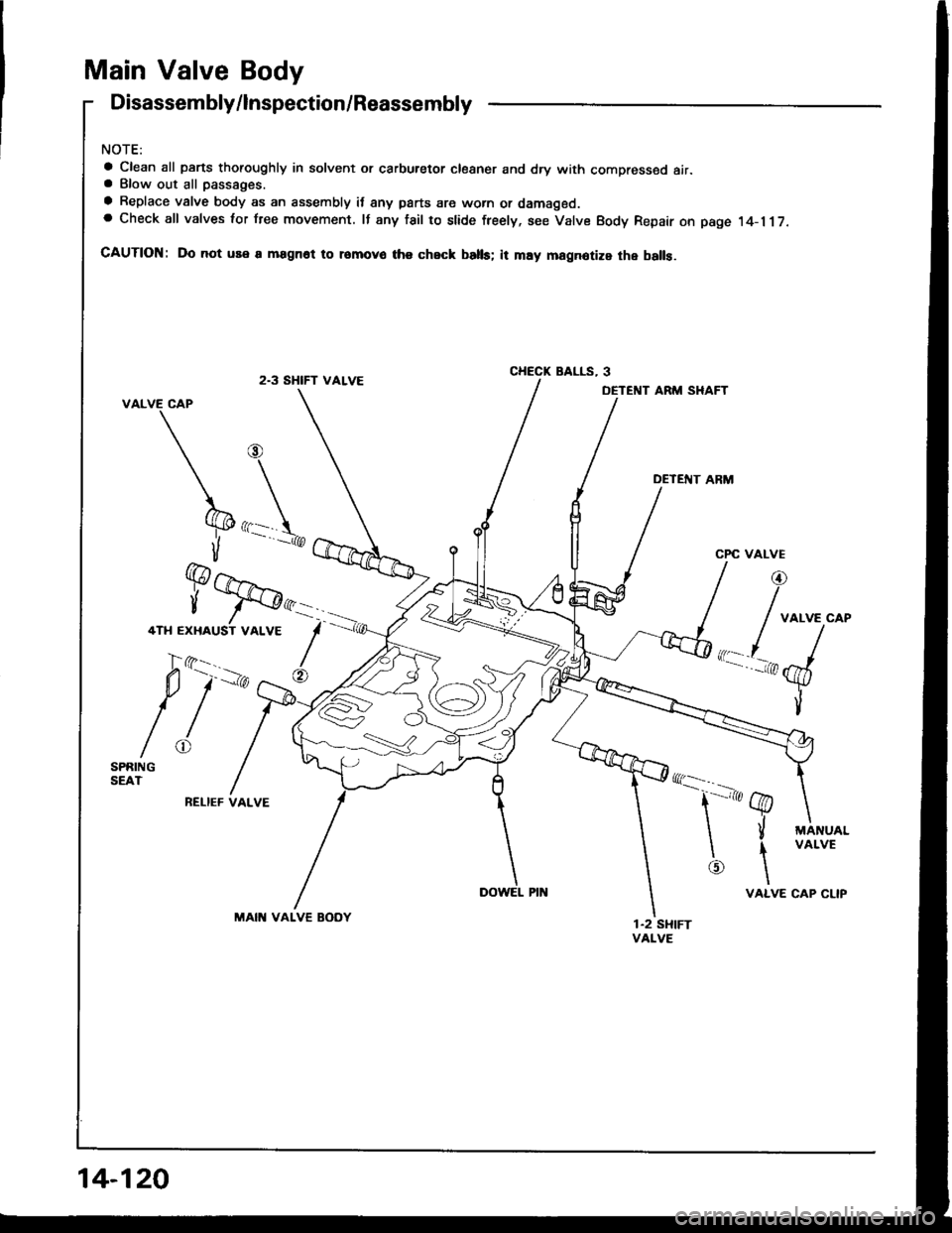
Main Valve Body
Disassembly/lnspection/Reassembly
NOTE:
a Clean all parts thoroughly in solvent or carburetor cloaner and dry with compressed air.a Blow out all passaoes.
a Replace valve body as an assembly it 8ny parts are worn or damaged.a Check all valves lor free movement. lf any fail to slide freely, see Valve Body Repair on page 14-117.
CAUTION: Do not use a magnot to romovo ths check batb; it may magnotize the balls.
2.3 SHIFT VALVECHECK BALLS, 3
DETENT ARM SHAFT
DETEfIT ARM
RELIEF VALVE
MAIN VALVE BODY
rrl \.
i
@
FJST VALVE
'-ir, ,^r
q---
t'-'t @
\il
\f
@\
VALVE
MANUALVALVE
CAP CLIP
14-120
Page 513 of 1413
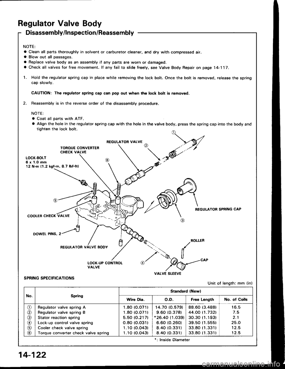
Regulator Valve Body
Disassembly/lnspection/Reassembly
NOTE:
a Clean all pans thoroughly in solvent or carburetor cleaner, and dry with compressed ait.a Blow out all passages.
a Replace valve body as an assembly it any parts are worn or damaged.a Check all valves for free movement. lf any fail to slide freely, see Valve Body Repair on page 14-117.
1. Hold the .egulator spring cap in place while removing the lock bolt. Once the bolt is removed. release the spring
cap slowlv.
CAUTION: The .egulator spring c8p can pop out whsn the lock bolt is removod.
2. Reassembly is in the reverse order of the disassembly procedute.
NOTE:
. Coat all pans with ATF.
a Align the hole in the regulator spring cap with the hole in the valve body, press the spring cap into the body andtighten the lock bolt.
LOCK.BOLT6 x 1.0 mm12 N.m (1.2 kgl.m, 8.7 lbf.ftl
REGULATOR SPRING CAP
COOLER CHECK
OOWEL PINS, 2
ROLLER
SPRING SPECIFICATIONS
Unit of length: mm (in)
../
I',.-2" ll"%=
VALVE SLEEVE
t,-V
,*6t'"
REGULATOR VALVE
REGULATOR VALVE BODY
No.Spring
Standard (New)
Wiro Dia.o.D.Free LonglhNo. of Coils
o/a
@
\9/
Regulator valve spring A
Regulator valve spring B
Stator reaction spring
Lock-up control valve spring
Cooler check valve spring
Torque converter check valve spring
1.80 (O.O71)
1.80 (0.071)
5.50 (O.2171
o.80 (o.o31)
1 .10 (0.043)
1 .10 (O.O43t
14.70 (O.5791
9.60 (0.378)'26.40 (1.O39)
6.60 (O.260)
8.40 (O.331)
8.40 (0.331)
88.60 (3.488t
44.OO t't.7321
30.30 (1 .1 93t
39.50 (1.555)
33.80 (1 .331 I
33.80 (1 .331 )
16.5
2.1
25.O'l2.5
12.5
14-122
lnside Diameter
Page 514 of 1413
NOTE:
a Clean all paris thoroughly in solvent or carburetor cleaner, and dry with compressed air.
a Blow out all passages.
a Replace valve body as an assembly it any parts are worn or damaged.
a Check all valves tor free movement. lf any fail to slide fre€ly, see Valve Body Repair on page 14-117.
a Coat all parts with ATF before reassembly.
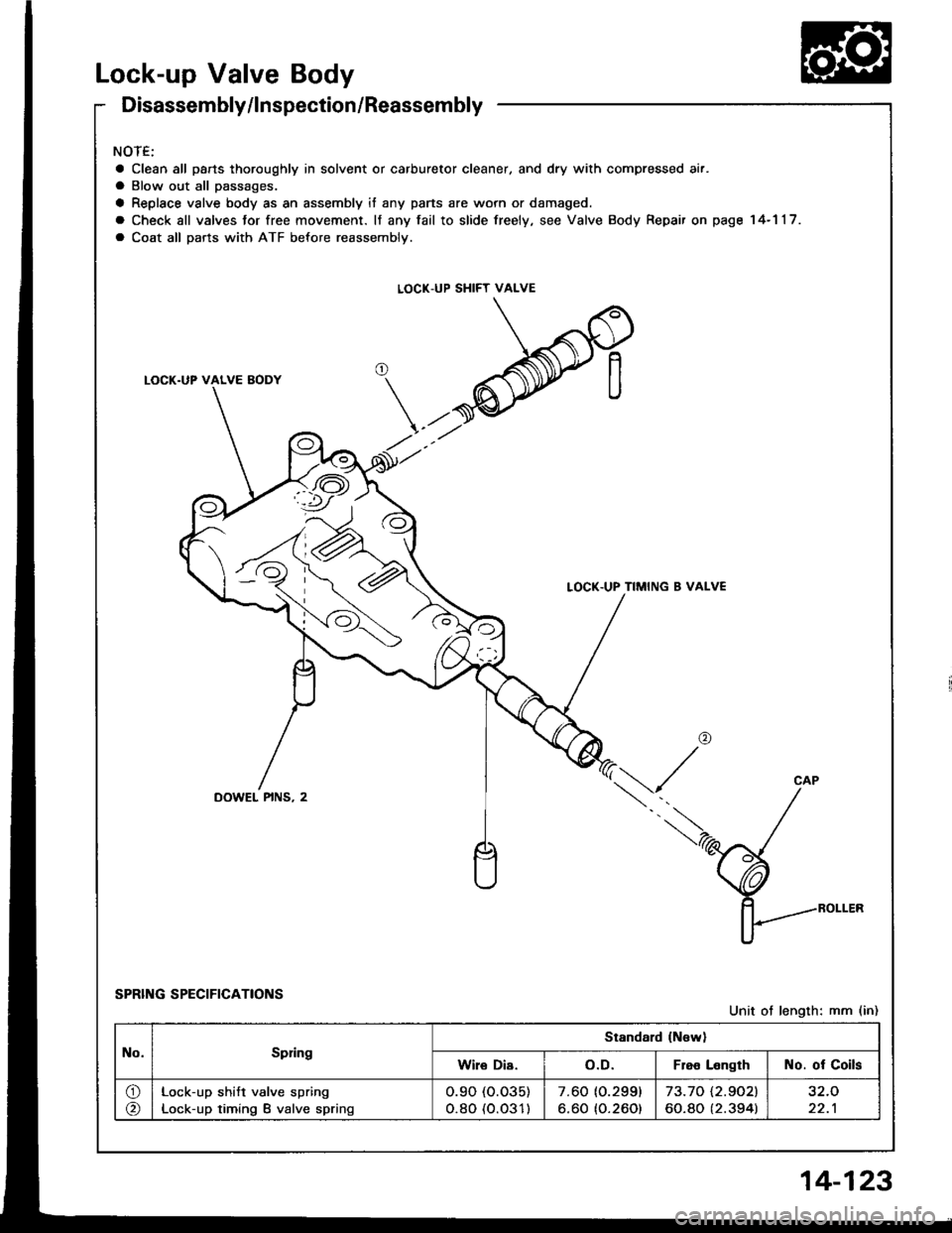
LOCK-UP SHIFT VALVE
LOCK.UP TIMING 8 VALVE
,ar
\,/
SPRING SPECIFICATIONS
CAP
Unit ot length; mm (in)
No.Spring
Standard {Nsw}
Wile Di8.o.D.Flee LengthNo. of Coils
o
@
Lock-up shift valve spring
Lock-up timing B valve spring
o.90 (o.035)
o.80 (o.031)7.60 (0.299)
6.60 {O.260)
73.70 i.2.9021
60.80 (2.394)32.O
22.1
Disassembly/lnspection/Reassembly
14-123
Page 515 of 1413
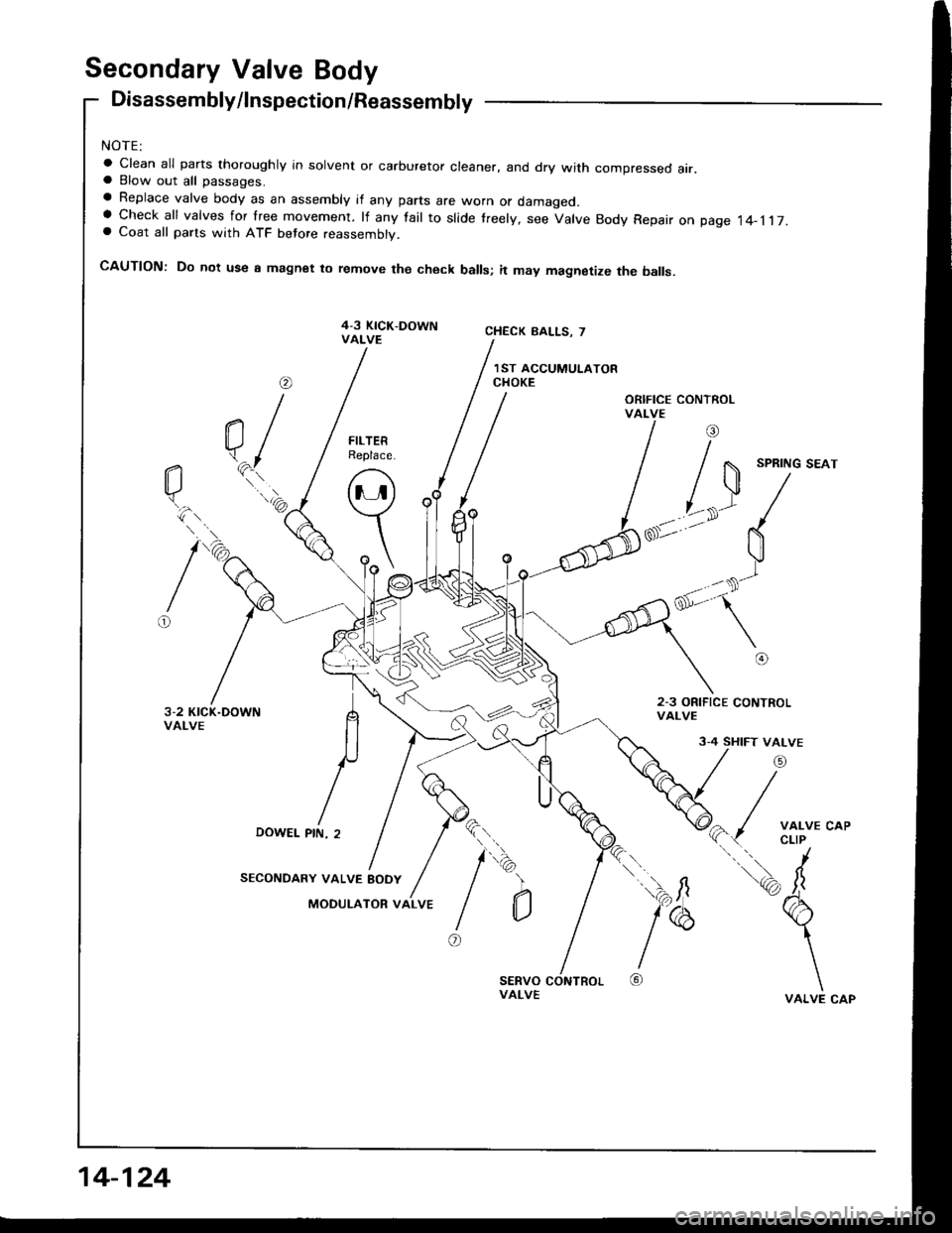
Secondary Valve Body
Disassembly/lnspection/Reassembly
NOTE:
a Clean all parts thoroughly in solvent or carburetor cleaner. and dry with compressed air.a Blow out all passages.
a Replace valve body as an assembly if any parts are worn or damageo.a check all valves for lree movement. rf any fair to sride treery, see varve Body Repair on page 14-1r7.a Coat all parts with ATF betore reassembly.
CAUTION: Do not use a magnet to remove the check balls; it may magnetize the balls.
@
a/\.^l"i\'.'.)
CHECK BALLS. 7
1ST ACCUMULATORCHOKE
\ll /
'-
o{
v-)--
\
@
,r/
a- / xii;.
trd
\VALVE
');fi
l"
@
SPRING SEAT
3-4 SHIFT VALVE
DOWEL
SECONDARY VALVE EODY
MODULATOR VALVE
nle
PIN, 2
2.3 ORIFICE CONTROLVALVE
\i\
I
o
b
)
a
14-124
Page 517 of 1413
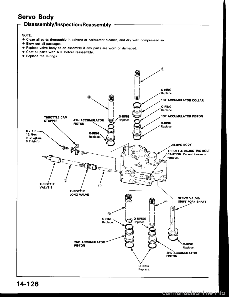
Servo Body
Disassembly/lnspection/Reassernbly
NOTE:
a Clean all pSrts thotoughly in solvent or carbu.etor cleaner, and dry with compressed air.a Blow out all passages.
a Replace valve body as an assembly it any parts are worn or damageo.a Coat all parts with ATF before resssemblv.a Replace the O-rings.
\P
@
Replace.
THROTTLE CAMSYOPPER
O-RINGReplace.4THPISTON
6 r 1.O mm12 N.m(1.2 kgf.m,8.7 rbt.ftl
SERVO BODY
THROTTLEVALVE B
I
o
THROTTLE ADJUSTIIIIG BOLTCAUTION: Do not loo3on or
O-RINGReplace.
3RD ACCUMULATORPISTON
i'rlll
V8;lilSl
LONG VALVE
14-126
Page 546 of 1413
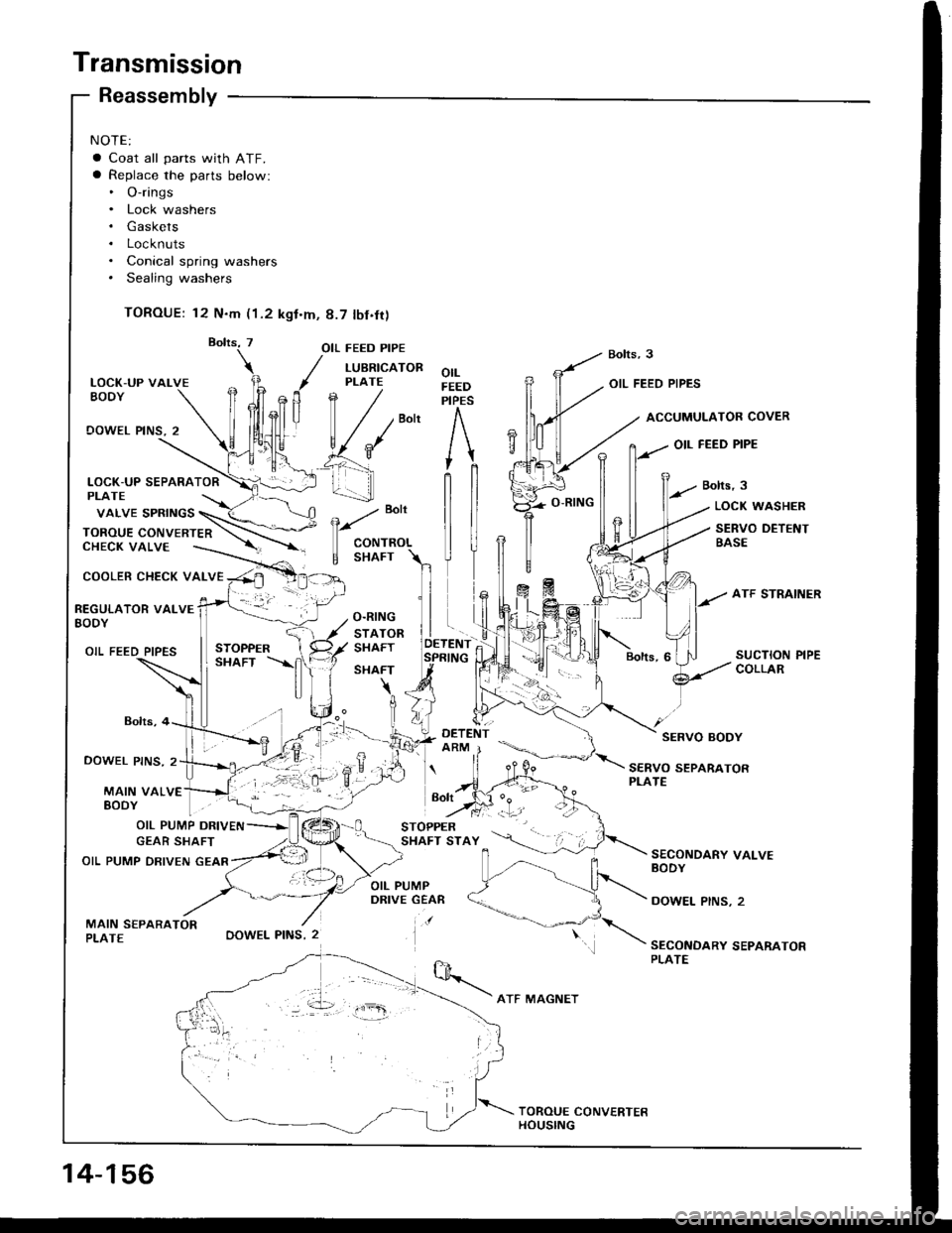
Transmission
NOTE:
a Coat all parts with ATF.a Replace the parts below:. O-rings. Lock washers. Gaskets. Locknuts. Conical spring washers. Sealing washers
TOROUE: 12 N.m (1.2 kgt.m, 8.7 tbf.fr)
LOCK-UP VALVEEODY
OOWEL PINS, 2
COOLER CHECK VALVE
Reassembly
Bolts,4
DOWEL PINS. 2
MAIN VALVE
OIL FEED PIPE
/ LUBRTcAToR
, PLATE
fln /
| / /""n
v{*' e'f _\
_! 1.-...-]]
-. :-,.
OOWEL PINS, 2
orLFEEDPIPES
OIL FEED PIPES
ACCUMULATOB COVER
OIL FEED PIPE
Bolts,3
e
"o't
CONTROL
E SHAFT
LOCK WASHER
SERVO DETENTBASE
REGULATOR VALVEBODY
OIL FEED PIPES
SERVO BODY
SERVO SEPARATORPLATE
EoDY | . "1-
OIL PUMP DRIVEN
GEAR SHAFT
OIL PUMP DRIVEN GEAR
MAIN S€PARATORPLATE
SECONDARY VALVEBODY
DOWEL PINS, 2
SECONDARY SEPARATORPLATE
vaLVE spRtNGS \_(< \
ToRou E coN vE RTE n \-\.--CHECK VALVE ----.-. --'r -
Bolt
14-156
ATF MAGNET
Page 547 of 1413
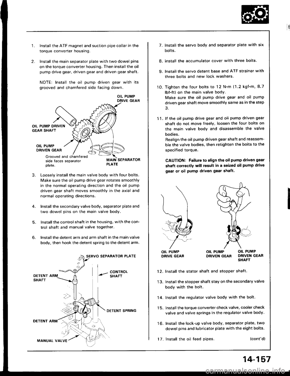
2.
1.Install the ATF magnet and suction pipe collar in the
torque converter nousrng.
Install the main separator plate with two dowel pins
on the torque converter housing. Then install the oil
pump drive gear, driven gear and driven gear shalt.
NOTE| Install the oil pump driven gear with its
grooved and chamtered side facing down.
OIL PUMPDRIVE GEAR
OIL PUMPORIVEN GEAR
Grooved and chamferedside faces separatorplate.
J.Loosely install the main valve body with Iour bolts.
Make sure the oil pump drive gear rotates smoothly
in the normal operating direction and the oil pump
driven gear shaft moves smoothly in the axial and
normal operating directaons.
Install the secondary valve body, separator plate and
two dowel pins on the main valve body.
Installthe control shaft in the housing, with the con-
trol shatt and manual valve togelher.
Install the detent arm and arm shatt in the main valve
body, then hook the detent spring to the detent arm.
SERVO SEPARATOR PLATE
--- 8ixli"'
6.
36
DETENTSHAFT
DETENT ARM
MANUAL VALVE
DETENI SPRING
17. Install the oil feed pipes.
14-157
E'.:
7. Install the servo body and separator plate with six
bolts.
8. lnstall the accumulator cover with three bolts
9. lnstall the servo detent base and ATF strainer with
three bolts and new lock washers.
10. Tighten the four bolts to 12 N.m (1.2 kgf'm, 8.7
lbf.ft) on the main valve body.
Make sure the oil pump drive gear and oil pump
driven gear shaft move smoothly same as in the step
11. lf the oil pump drive gear and oil pump driven gear
shaft do not move freelY. loosen the four bolts on
the main valve body and disassemble the valve
bodies.
Realign the oil pump driven gear shaft and reassem-
ble the valve bodies, then retighten the bolts to the
specified torque,
CAUTION: Failure to align the oil pump d1iv6n gear
shaft corroctly will result in a seized oil pump drivo
geal of oil pump drivon gear shatt.
l\
(...l
=..�N
L,1ffi#
j-*/:
OIL PUMPDRIVE GEABOIL PUMP OIL PUMPDRIVEN GEAR DRIVEN GEARSHAFT
12. Install the stator shaft and stopper shatt.
13. Install the stopper shatt stay on the secondary valve
body with the bolt.
14. Install the regulator valve body with the bolt.
1 5. Install the torque converter check valve, cooler check
valve and valve springs in the requlator valve body.
16. Install the lock-up valve body, separator plate, two
dowel pins and lubricator plate with the eight bolts.
(cont'dl
Page 623 of 1413
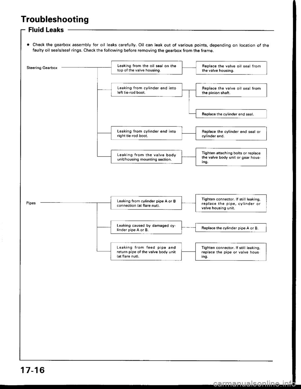
Troubleshooting
Fluid Leaks
Check the gearbox assembly for oil leaks carefully. Oil can leak out of various points. depending on location of thefaulty oil seals/seal rings. Check the following before removing the gearbox from the frame.
Steering GearboxLeaking from the oil seal on thetop of the valve housing.Roplace the valve oil seal fromthe valve housing.
Leaking from cylinder end intoleft tie'rod boot.Replace the valve oil seal lromthe pinion shaft.
Reolace the cvlinder end seal.
Leaking from cylinder end intoright tie rod boot.
Tighten attaching bolts or replacethe valve body unit or gear hous-Ing.
Leaking from the vslve bodyuniVhousing mounting soction.
Tighten connector. It still leaking.replace the pipe, cylinder orvalve housing unil.
Leaking from cylind6r pipe A or Bconnection (at tlare nut).
Leaking caused by damaged cy-linder pipe A or B.Replace the cylinder pipe A or B.
Leaking from feed pip6 andreturn pipe of the valve body unit(at flare nut).
Tighten connector. lI still leaking,replace the pipe or valve housIn9,
17-16
Page 628 of 1413
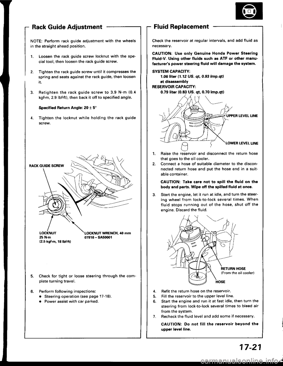
NOTE: Perform rack guide adjustment with the wheels
in the straight ahead position.
Loosen the rack guide screw locknut with the spe-
cialtool, then loosen the rack guide screw.
Tighten the rack guide screw until it compresses the
spring and seats against the .ack guide, then loosen
it.
Retighten the rack guide screw to 3.9 N.m {0.4
kgf'm, 2.9 lbf.ft), then back it off to specified angle.
Specified R6turn Angle: 20 t 5"
Tighten the locknut while holding the rack guide
screw.
1.
6.
RACK GUIDE SCREW
25 N.m12.5 kgf.m, 18lbtftl
L(rcKNUT WRENCH, 40 mm07916 - SAs(xtOl
Check for tight or loose steering through the com-
plete turning travel.
Perform following inspections:
. Steering operation (see page 17-18).
. Power assist with car parked.
Check the reservoir at regular intervals. and add fluid as
necessary.
GAUTION: Use only Genuine Honda Power Stosring
Fluid-V. Using othsr fluids such as ATF or other manu-
facturer's power stoering fluid will damags ths systcm,
SYSTEM CAPACITY:
LO6 litor (1.12 US. qt, 0.93 lmp.qtl
at disasssmbly
RESERVOIR CAPACITY:
0.79 lit6r (0.8:l US. qt, 0.70 lmp.qt)
UPPER LEVEL UNE
LOWER LEVEL LINE
,l
Raise the reservoir and disconnect the return hose
that goes to the oil cooler.
Connect a hose of suitable diameter to the discon-
nected return hose and put the hose end in a suit-
able container.
CAUTION: Tako caro not to 3pill tho tluid on tho
body and parts. Wipe off the spilled tluid at onqe.
Start the engine. let it run at idle. and turn the steer-
ing wheel from lock-to-lock several times. When
fluid stops running out of the hose, shut off the
engine. Discard the fluid,
Refit the return hose on the reservor.
Fill the reservoir to the uDoer level line.
Start the engine and run it at fast idle, then turn the
steering from lock-to-lock several times to bleed air
f.om the system.
Recheck the fluid level and add some if necessary.
CAUTION: Do not lill the roservoir beyond tho
uppgr lovel line.
7.
Page 629 of 1413
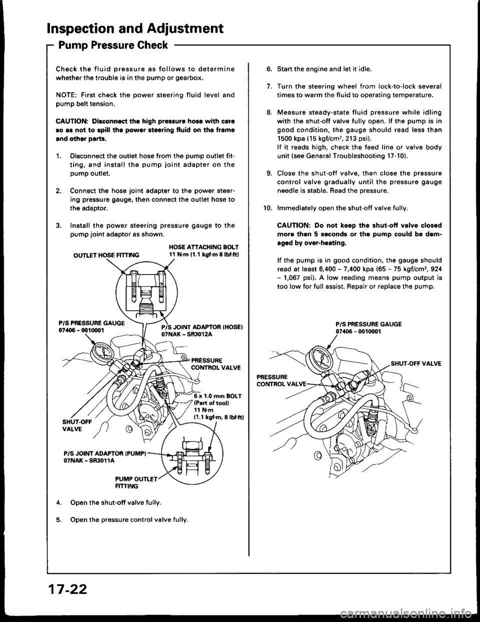
lnspection and Adjustment
Pump Pressure Check
Check the fluid pressure as follows to determine
whether the trouble is in the pump or gearbox.
NOTE: First check the power steering fluid level and
pump belt tension,
CAUnON: Dilconn€st the high pros3uro ho3s with cale
!o e3 not to spill tho powor stooring fluid on th6 lramo
lnd olhor parG.
1. Disconnect the outlet hose from the oumo outlet fit-
ting, 8nd install the pump joint adapter on the
pump outlet.
2, Connect the hose joint sdapter to the power steer-
ing pressure gauge, then connect the outlet hose to
the adaotor.
3. Instsll the power steering pressure gauge to the
pump joint adaptor as shown.
OUTLET HOSE FlTnNG
HOSE ATTACHING BOLT1l Nm11.1 kg{ m 8lbf.ftl
6 x 1.0 m.n BOLT{P!rt of tooll11 N.m11.1 kgtm,8lbf.ftl
P/S JOINT ADAPTOR IPUMPIo?NAK - SmolrA
PUMP OUTI.TTFITIING
Open the shut-off valve fully.
Open the pressure control valve fully.
17 -22
1.
Start the engine and let it idle.
Turn the stee.ing wheel from lock-to-lock several
times to warm the fluid to operating temperature.
Measure steady-state fluid pressure while idling
with the shut-off valve fully open. lf the pump is in
good condition, the gauge should read less than
1500 kpa (15 kgf/cm,,213 psi).
lf it reads high, check the feed line or valve body
unit (see General Troubleshooting l7-10).
Close the shut-off valve. then close the pressure
control valve gradually until the pressure gauge
needle is stabl6, Read the pressure.
lmmediately open the shut-off valve fully.
CAUTION: Do not keep the shut-ott valvs closod
moro thgn 5 soconds or th9 pump could b6 dam"
agod by over-h6ating,
lf the pump is in good condition, the gauge should
read at least 6.400 - 7,400 kpa (65 - 75 kgIlcm,,924- 1,067 psi). A low reading means pump output is
too low for full assist. Repair or replace the pump.
10.
P/S PRESSURE GAUGE