ac circuit HONDA INTEGRA 1994 4.G Workshop Manual
[x] Cancel search | Manufacturer: HONDA, Model Year: 1994, Model line: INTEGRA, Model: HONDA INTEGRA 1994 4.GPages: 1413, PDF Size: 37.94 MB
Page 4 of 1413
,,
SUPPLEMENTAL RESTRAINT SYSTEM (SRS}
The Integra SRS includes a driver's airbag, located in the steering wheel hub. ln addition, all mod€ls excepi tna
Rs model for canada have a front passenger's airbsg located in the dashboard above the glove box, InformaUon
necessary to safely service the SRS is included in this servica Manual. ltems marked with an sstorisk (r) on thr
contents page include, or are located near, SRS components. Servicing. disassembling or roplacing thea6 ltems
will require special precautions and tools, and should thoreiore be done by an authorhed Acura dealer.
' To avoid rondering ths sRS inoporativo, which could lard to porronll Injury or darth In thc cvant ot. r.yr.
trontal collision, all sRs sorvico work must be pcrformcd by !n ruthorizcd Acu.! daerrr,
' lmpTopor 3orvica proceduroa, including inco.roct r.movd r d Installation of tha SRS, could Lld to pc[onc Inlu-
ry caussd by unintsntional activation ot tho airbags.
' All sRs oloctrical wiring harnoa$! aro coverod with yallow In3ulatlon, Rcbtcd componcnts arc bcrtad In tha
stoering Golumn, front console, dsrhboa.d, and darhboard lowor plnol, lnd in thc d$hbolrd abovc tha gaov!
bor. Do not uas oloctdcal te$ oquipmont on thaaa citcuhs.
NoTE: The original radio has a coded thett protection circuit. Be sure to get the customer's code numb6r b€lore* disconnecting the battery.
- removing the No. 32 (7.S A) fuse Jrom the undsr-hood fuse/relay box.
- removing the radio.
After service, reconnect power to the radio and turn it on. When the word ,,CODE,, is displayed, enter the cus_
tomer's 5-digit code to restore radio oDerauon.
Page 48 of 1413
Engine Removal/lnstallation
@a Make sure jacks and safety stands aro placed ploper-
ly and hoisl brackots arg attachod to the correct po-
sitions on tho engine (se€ ssction 1).
a Mak€ sure tho car willnot roll off stands and tallwhile
you are wotking under it'
CAUTION:
a Use fendet covals to avoid damaging painted
sudaces.
r Unspecified itsms alo common
a Unplug tho widng connectots carefully while holding
the couplor and tha connector portion to avoid
oamage.
a Mark all wiring and hoses to avoid misconnection.
Also, be sulo that thsy do not contact other wiring
or hoses, or interfere with oth€l parts.
NOTE: Anti-theft radios have a coded theft ptotection
circuit. Be sure to get the customer's code number beJore
- Disconnecting the batterY.
- Removing the No. 32 (7.5 A) fuse from the under-
hood tuse/relay box.- Removing the radio
Atter service, reconnect power to the radio and turn it
on. When the word "CODE" is displayed, enter the cus-
tomer's 5-digit code to restore radio operataon.
1. Remove the hood (see section 2O).
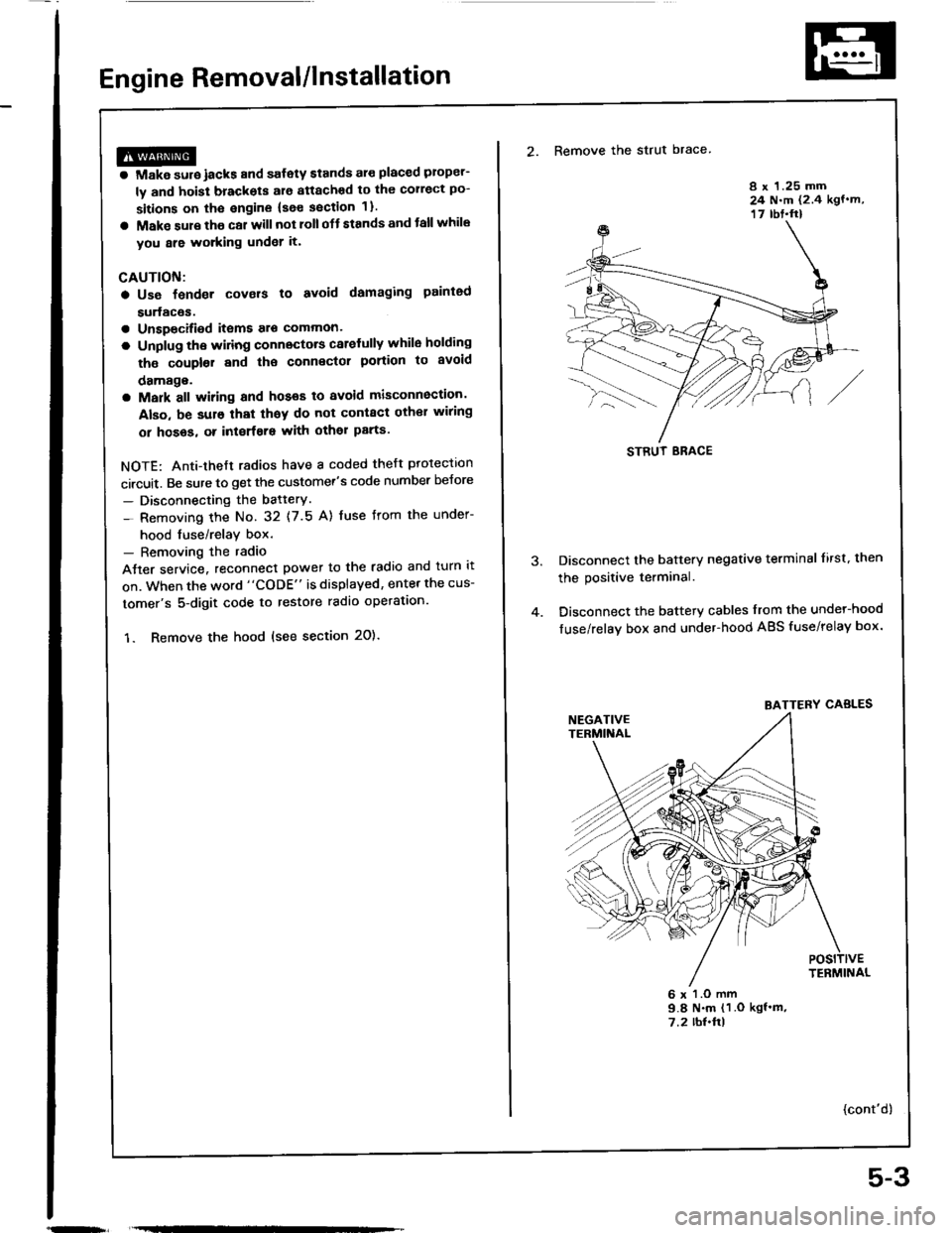
2. Remove the strut brace
8 x 1.25 mm24 N.m (2.4 kgf.m,17 rbt.ft)
Disconnect the battery negative terminal lirst. then
the positive terminal.
Disconnect the battery cables from the undel-hood
fuse/relay box and under-hood ABS fuse/relay box.
6 x l.O mm9.8 N.m (1 .O kgf'm,7.2 rbl.ftl
{cont'd)
STRUT ERACE
BATTERY CABLES
5-3
Page 78 of 1413
Gylinder Head
Removal
I
t
Engine removal is not required for this procedure.
CAUTION: To avoid damaging tho cylinder head, wait
until tho ongino coolant temporature drops bolow 100"F
{38"C) beforo loo36ning the rotainin0 bolts.
NOTE:
. Inspect the timing belt before removing the cylinder
neao.
. Turn the crankshaft pulley so that the No. 1 piston is
at top dead center (TDCI (page 6-12).
. Mark all emissions hoses before disconnecting them.. Anti-theft radios have a coded theft protection circuit.
Be sure to get the customer's code number before.- Disconnecting the battery.- Removing the No. 32 (7.5 A) fuse irom the under-
hood fuse/relay box.- Removing the radio.
After service, reconnect oower to the radio and turn it
on.
When the word "CODE" is displayed, enter the cus-
tomer's 5-digit code to restore radio operation.
1. Disconnect the negative terminalfrom the battery.
2. Drain the engine coolant (see page 10-5).
. Remove the radiator cap to speed draining.
3. Relieve fuel pressure (see Section 1 1).
@ Do not smoke whils working on tusl
systom, keep opon flame or spark away trom work
area. Drain fuol only inlo an approvod containsr.
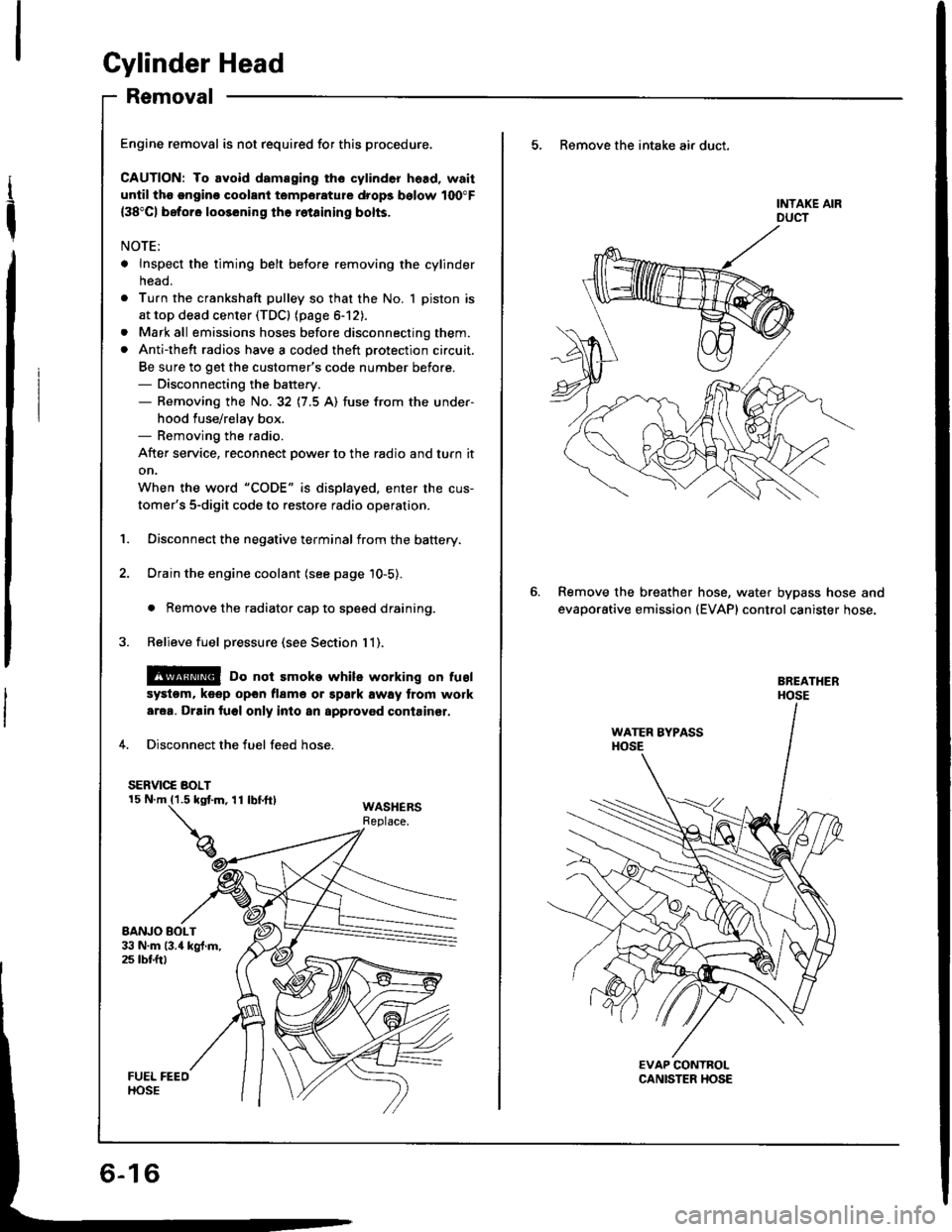
4. Disconnect the fuel feed hose.
SERVIC€ BOLT
WASHERSReplace.
5, Remove the intake air duct.
Remove the breather
evaporative emission
hose, water bypass hose and(EVAP) control canister hose.
Page 99 of 1413
wEc
6-38
Troubleshooting Flowchart - VTEC Pressure Switch
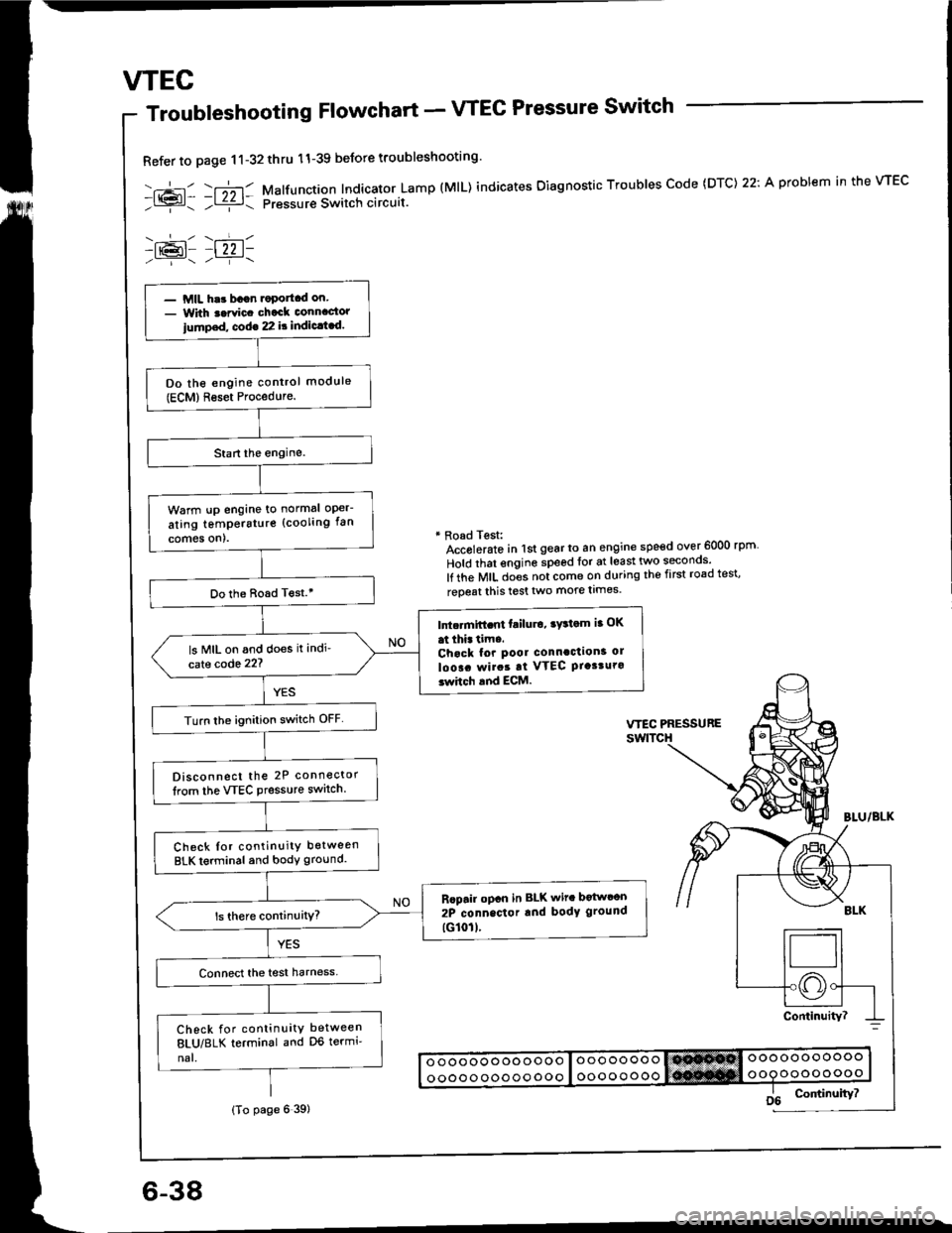
Refer to page 11-32thru 11-39 beJore troubleshooting'
-.+- -r";-r- Malfunction Indicator Lamp (MlL) indicates Oiagnostic Troubles Code (DTC) 22: A problem in the VTEC- l{{?l- ;l ziz r: pressur€ Switch circuit.
-lr@l- |22 1-
* Road Test:Accolerato in lst gear to an engine speed over 6000 rpm
Hold that engine speed for at least two seconos'
lf the MIL does not come on during the first road test'
reoeat this test two more limes.
- MIL har bagn.oportcd on.- With t.rvic. chack connactor
iump.d, cod€ 22 it indic.t.d.
Do the engine control module(ECM)Reset Procedure.
Warm !p engine to normal oper-
ating temperstur€ (cooling fan
comes on).
Do the Boad T€st.'
Intc.mift.nt failu.o, ry3tom ia OK
at thi. tim..Chack for pool connaction3 ol
loo!. rvirat at VTEC Ptasturo3whch and ECM.
ls MIL on and does it indi'
cate code 22?
Turn lhe ignition switch OFF
Disconnect the 2P connector
lrom the VTEC Pressure switch.
Check Ior continuity between
BLK terminal and body ground.
Rcpair opcn in BLK wit. botwcon
2P connector rnd body ground
tG101l.
Check for continuity between
8LU/8LK terminal and D6 termi'
nal.
(To page 6 39)
Page 116 of 1413
Cylinder Head
Removal
Engine removal is not required or this procedure.
CAUTION: To avoid damaging tho cylinder head, wail
u[tilths.nginc coolant tsmperaturo drops bolow 100"F(38'Cl bafore loos6ning tho retaining bolts.
NOTE;
. Inspect the timing belt before removing the cylinder
head.
Turn the crankshaft pulley so that the No. 1 piston is
at top dead center (TDc) {page 6-51).
Mark all emissions hoses betore disconnecting them.
Anti-theft radios have a coded theft protection circuit.
Be sure to get the customer's code number before- Disconnecting the battery.- Removing the No.32 (7.5 A) fuse trom the under-
hood fuse/relay box.- Removing the radio.
After service, reconnect power to the radio 8nd turn it
on.
When the word "CODE" is displaved. enter the cus-
tomer's 5-digit code to restore radio operation,
Disconnect the negative terminal from the battery.
Drain the engine coolant (see page 10-5).
. Remove the radiator cap to speed draining.
Relieve fuel pressure (see section 111.
l@ Do not 3moke whilo working on fuel
a
a
'1.
systgm. ko6p opon tlamo ot Spark away trom work
aroa. Drain fugl only into an approved containsr,
4. Disconnect the fuel feed hose.
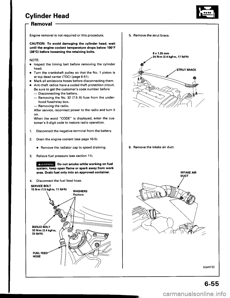
SERVIC€ BOLT15 N.m (1.5 kgtm, rl bf.tt)WASHERSReplace.
BANJO BOLT
5. Remove th€ strut brace,
6. Remove the intake air duct.
8 x 1.25 mm24 N.m (2.1kg[.m, 17 lbtftl
INTAKE AIR
(cont'd)
6-55
Page 228 of 1413
Troubleshooting
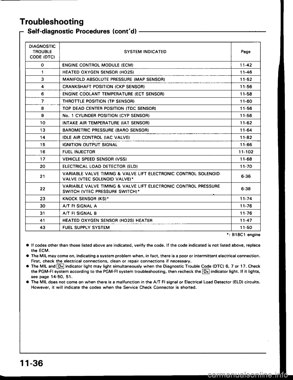
Self-diagnostic Procedures (cont'dl
':818C1 engine
a lf codes other than those listed above are indicated, verifv the code. lf the code indicated is not listed above, replace
rhe ECM.
a The MIL may come on, indicating a system problem when, in fact, there is a poor or intermittent electricalconnection.
First, check the electrical connections, clean or repair connections it necessary.
o The MIL and @ indicator light may light simultaneously when the Diagnostic Trouble Code (DTC) 6, 7 or 17. Check
the PGM-Fl system according to the PGM-Fl system troubleshooting, then recheck the l!! indicator light. ll it lights,
see page 14-5O, 51.
a The MIL does not come on when there is a malfunction in the A/T Fl signal or Electrical Load Detector (ELDI circuits.
However, it will indicate the codes when the Service Check Connector is shorted.
DIAGNOSTIC
TROUBLE
CODE (DTCISYSTEM INDICATEDPsge
oENGINE CONTROL MODULE IECM)11-42
,lHEATED OXYGEN SENSOR IHO25)1 1-46
aMANIFOLD ABSOLUTE PRESSURE {MAP SENSOR)11-52
4CRANKSHAFT POSITION (CKP SENSOR)1 1-56
oENGINE COOLANT TEMPERATURE (ECT SENSOR)11-58
THROTTLE POSITION (TP SENSOR}11-60
ITOP DEAD CENTER POSITION (TDC SENSORI1 1-56
9No. 1 CYLINDER POSITION (CYP SENSOR)1 1-56
10INTAKE AIR TEMPERATURE (IAT SENSOR)11-62
13BAROMETRIC PRESSURE (BARO SENSOR}1|-64
14IDLE AIR CONTROL (IAC VALVE}11-42
tcIGNITION OUTPUT SIGNAL11-66
toFUEL INJECTOR1't-102
17VEHICLE SPEED SENSOR {VSSI11-68
20ELECTRICAT LOAD DETECTOR (ELD)'t 1-70
21VARIABLE VALVE TIMING & VALVE LIFT ELECTRONIC CONTROL SOLENOID
VALVE {VTEC SOLENOID VALVE)'6-36
22VARIABLE VALVE TIMING & VALVE LIFT ELECTRONIC CONTROL PRESSURE
SWITCH (VTEC PRESSURE SWITCHI-6-38
23KNOCK SENSOR {KS}-11-7 4
30A/T FI SIGNAL A11-76
3'rA/T FI SIGNAL B1 1-76
4'lHEATED OXYGEN SENSOR (HO25} HEATER11-47
43FUEL SUPPLY SYSTEM1 1-50
11-36
Page 238 of 1413
PGM-FI System
Heated Oxygen Sensor lHO2Sl
ztRcot{lAELEiIE'{T
HEATER
- --.'!- - -__-
lrPl _l !l-
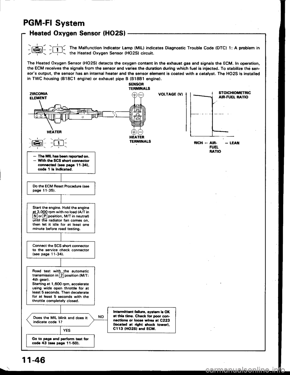
-fi-l: The Malfunction Indicator Lamp (MlL) indicates Diagnostic Troubls Code (DTC) 1: A problsm in
/? the Heated Oxygen Sonsor (HO2S| circuit.
The Heated Oxygen Sensor IHO2S) det€cts th6 oxygon contont in th6 exhaust gas and signals th6 ECM. In operation,
the ECM receiv€s th6 signals trom the sensor and vari€s the duration during which tu6l is iniocted. To stabilize thd sen-aor's output, tho sensor has 8n intarnal heater and the sensor olemant is coatod with a catslyst. The HO2S is installod
in TWC housing (B18Cl engine) or exhaust pipe B (Bl8Bl €ngine).
sEl{SORTERMII{ALS
:tz-t6l-/ --.- \
VOLTAGE (V}sTotcHtoltETncAIR-FUEL BANO
HEATEBTEBMIT{ALSRICH - AN. - LEAI{FUELRATIO- Th! mll h.. bo.n raportad on.- Wlth thr SCS rhon coon cto.connoctad lr.. p!9. 1t-341,cod. t l. Indlcltrd.
Oo th€ ECM Res€t Procodure {soopag€ 11-35).
Stan the 6ngine. Hold th6 engine
A3,qgq rpm with no load {A/T in
Lryl or lll position, M/T in nourralluntil the radiator lan com6s on.then lot it idle lor ot least on6minutg beforo road t€6tin0.
Connoct ths SCS short connoctorto th6 sorvic€ check connectorlsoo p.g6 1 1-34).
Rood t€st witlthe automatictransmission in L?l position (M/T:4th gear).Stsrting st l,600 rpm, acc6lorateu6ing wide open throttlo for atlesgt 5 seconds. Thsn dgcol€rstefor at lorst 5 s€conds with th€throttlo completoly closed.
Intarmittd[ t llurc, lyri.m b Of!l thla tlmc. Ch.ck lor poor con-nacdona o? loota wlrat |l C223(loc.trd at right $ock towo.l,Cr 13 (HO2S| lnd ECM.
Ooes the MIL blink and doos itindic6t6 cod6 1?
Go to plga and partonn tad fotcod. 43 lr.a p.go l1-501.
1 1-46
Page 239 of 1413
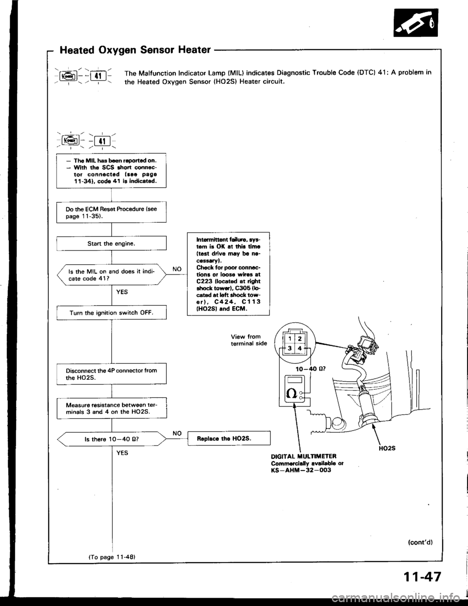
mll )ffltl The Malfunction Indicator Lamp (MlL) indicates Diagnostic Trouble Code (DTCI 41: A problem in
Y- -:- the Heated Oxygen Sensor {HO2S) Heater circuit.
-.----r- \- l-l
tt(gt- -t tt I-r---7r
DIGITAL MULTIMETEBCommorcially availablo orKS-AHM-32-OO3
- Th6 MIL has boen roponod on.- With the SCS rhort connoc-to. connociod (aoe pago
11-341. codo 41 is indic.tod.
Do the ECM Reset Procedure {seepage 11-351.
Intoamittont tdl||.g, ryr-t m i3 OK at thi! timo(tost driv6 lnay bg ns-cearatYl.Chock tor poor conn6c-tions or looro wires atC223 llocatod at rightshod( row..l, C3O5 {lo-cated 6t loft ahock low-or), C424, C113(HO2S) and ECM.
ls the MIL on and does it indi-cste code 41?
Turn the ignition switch OFF.
Measurc tasistance betwgen ter-minals 3 snd 4 on the HO2S.
ls thero 1O-4O 0?
t€rminal side
(To page 1 1-481
(cont'd)
Page 242 of 1413
PGM-FI System
rj-t
--t-.
Fuel Supply System
-+-lt@t- -t 13 |- ' "- - --i--
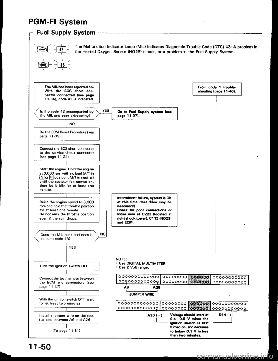
T,-n The Maltunction Indicator Lamp (MlL) indicares Diagnostic Trouble Code (DTC) 43: A problem in
- L:!-i - the Heated Oxygen Sensor (HO2S) circuit. or a probtem in the Fuel Supply System.
NOTE:. Use DIGITAL MULTIMETER.. U6e 2 Volt rang6.
o oooooo oooooo I oo oooooooooooooooooooQoo ooo ooooo I oooo ooooooooooooooo
426
JUMPER WIRE
o ooooo oooo ooo I oo oooooo Isdtcllodsl ooo ooooooooo oooo ooo oo ooo I oooo ooooooooooooooo
D14 {+l
I
426 t-l vohrgo rhould rl.n.t
| 0.4-0.5 V wh.n th..- ignirioo .wilch i! firdt|rtrod o.r, Itd docr!6ato b.low O.1 V in L..th6n two minutaa.
- Tho MIL h.s boen reportod on.- With rhe SCS short con-noctor connocted (soo paga1l-34), codo 43 b indlcat.d,
From codr I troebl.-lhoorlng lprgo 1146).
ls the code 43 accompanied bythe MIL and poor driveability?Go to Fuol Supply .y.t.m (|ecpag6 1t-971.
Do the ECM Reset ftocedure lseepage 11-35).
Connect the SCS short connectorto the service check connector{see page 'l1-34).
Start the engine. Hold the engineat 3,00O rDm with no load {A/T in
@or@ position, M/T in neutral)until the radiator Ian comes on,then let it idle for at least onemanute,
Intonnitl.nt t llure, tydom lr OKat thi. tim. lto.t drlv. mly b.nocaararyr.Chock lor poo? connactlona otloots wiro at C223 lloc.t.d atrlghl lhock towo.]. Cl13lHO2Sland ECM,
Raise the engine speed to 3,000rpm and hold that throttle positiontor at least one minute.Do not vary the throttle positioneven if the rpm drops.
Ooes the MIL blink and does itindicate code 43?
Turn the ignition swilch OFF.
Connect the test harness betweenthe ECM and conneclors {seepage 1 1-371.
With the ignition switch OFF, waitfor at least two minutes.
lnstall a jumper wire on the testharness between A6 and A26.
11-50
1To page 1 1-5'l l
Page 244 of 1413
PGM-FI System
Manifold Absolute Pressure (MAP) Sensor
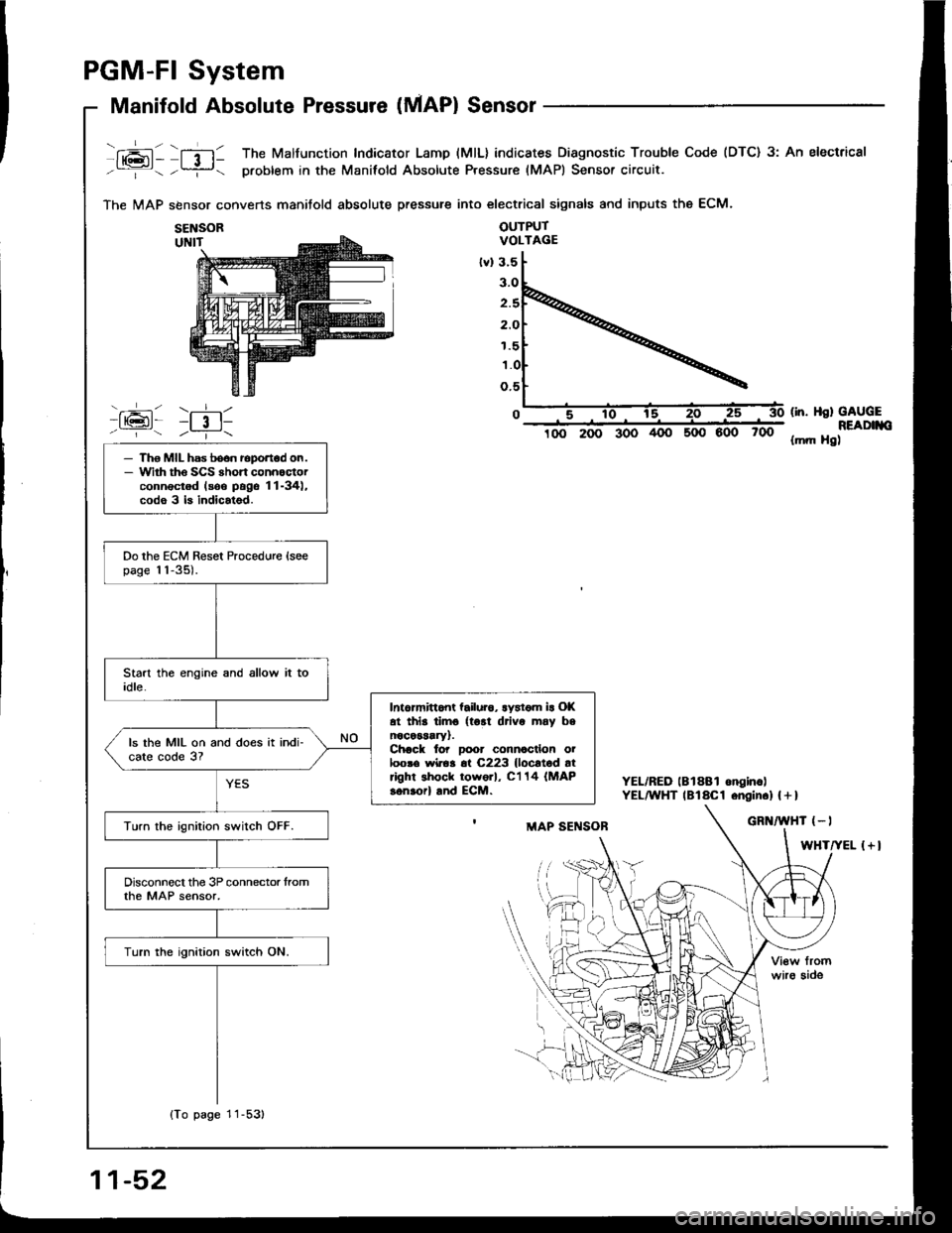
fxai - lfil1 The Malfunction Indicator Lamp (MlL) indicates Diagnostic Trouble Code (DTC) 3: An electrical
-:- -?- problem in the Manifold Absolute Pressure (MAPI Sensor circuit.
The MAP sbnsor converts manitold absolute pressure into electrical signals and inputs the ECM.
OUTPUTVOLTAGE
600 700
(in. Hsl GAUGEREADIIIO{mft Hg)
YEL/RED lBlSBl onginc)YEL^YHT lBlaCl .ngin.l | + I
{+l
SENSOR
1.5
- Tho MIL has boon roportod on.- Wirh tho SCS rhort connoctorconnectod lsoo pags 11-34),codo 3 b indicatsd.
Do the ECM Reset Procedure {soepage 11-35).
Intormittont tailuro, lystom ir Ol(at thls timo {tort drivo may bsnocessary).Chack to? Door connocllon oiloosa wiroa 6t C223 {locltod atright shock tow6rl, C'l 14 (MAP
sonaorl and ECM.
ls the MIL on and does it indi-cate code 3?
Turn the ignition switch OFF.
Disconnect the 3P connector tromthe MAP sensor,
Turn the ignition switch ON.
{To page 11-53)
11-52