Transmission HONDA INTEGRA 1998 4.G Workshop Manual
[x] Cancel search | Manufacturer: HONDA, Model Year: 1998, Model line: INTEGRA, Model: HONDA INTEGRA 1998 4.GPages: 1681, PDF Size: 54.22 MB
Page 1460 of 1681
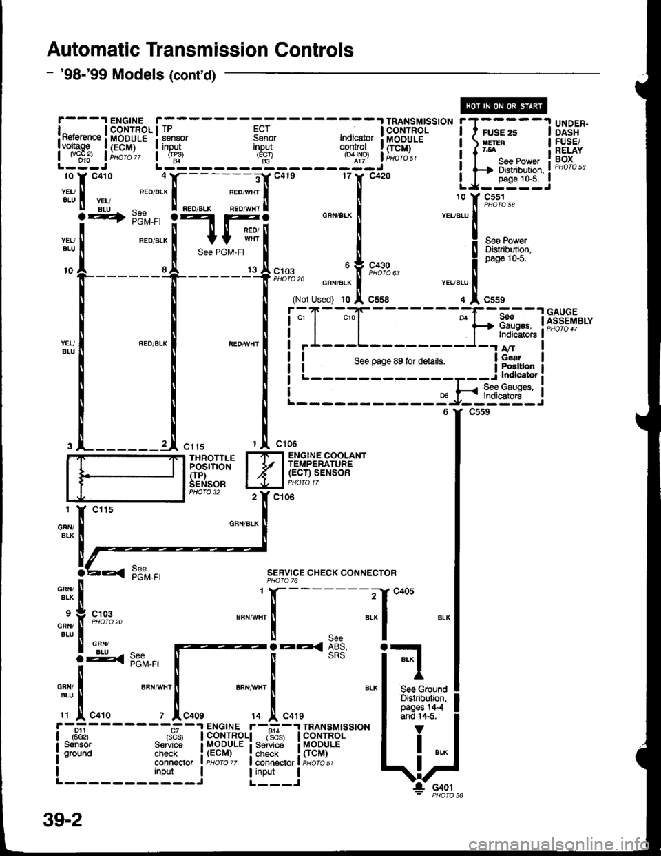
Automatic Transmission Controls
- '98-'99 Models (cont'd)
YEUatu
-ry
UNDER-DASHFUSE/RELAYBOX
SERVICE CHECK CONNECTOR
1l[----- -i-f c+os
"""t"'
I see
-^
|.EE< ABS,
i-1
Ti:
t':,;"'1...,
*";'1".,,
- sRS
""1
#t*r-^:----- ENGTNE r--:-I TRANSM|SS|ON I rI r*ib rsis, I coNTRoLl r"sb'sr I coNTRoL I i
fl i$yjHlr'!;f#n",!ffiii:' \i- !- G401- PHOTO 56
r)J-1
i*J itTffe.- ir:";-
- - - -
s:I-
- - - -
;;; I HffilEr''". i T r.s:;
- -
II voliage l{ECM) | input
I w,?- | i.o, o,, L :t - - - - - jrfl - - - - - Si
j hfiY:t'
".
i 1-%** i
l_: f, "o'oror c410 4tr-------E[c4ts 17tr' c420 LJ__HSIJ
:ii t Hb ^f'""'* ! "."".* :;;! !
';l "lz*"
-
-[ ;;
"*i*'*i[Try[",".
""."]1,**^ "'""'"!
*u*u''o
ft_ _ _____+___ _ _'lfi g;to,..,. o"n,"J, f t",",,
Page 1461 of 1681
rolr--------- .r1
r-r onuer-r I
fiEg-< s"".-
"""::F'l;;l
^."""1"""*'[ "-'"1 "--
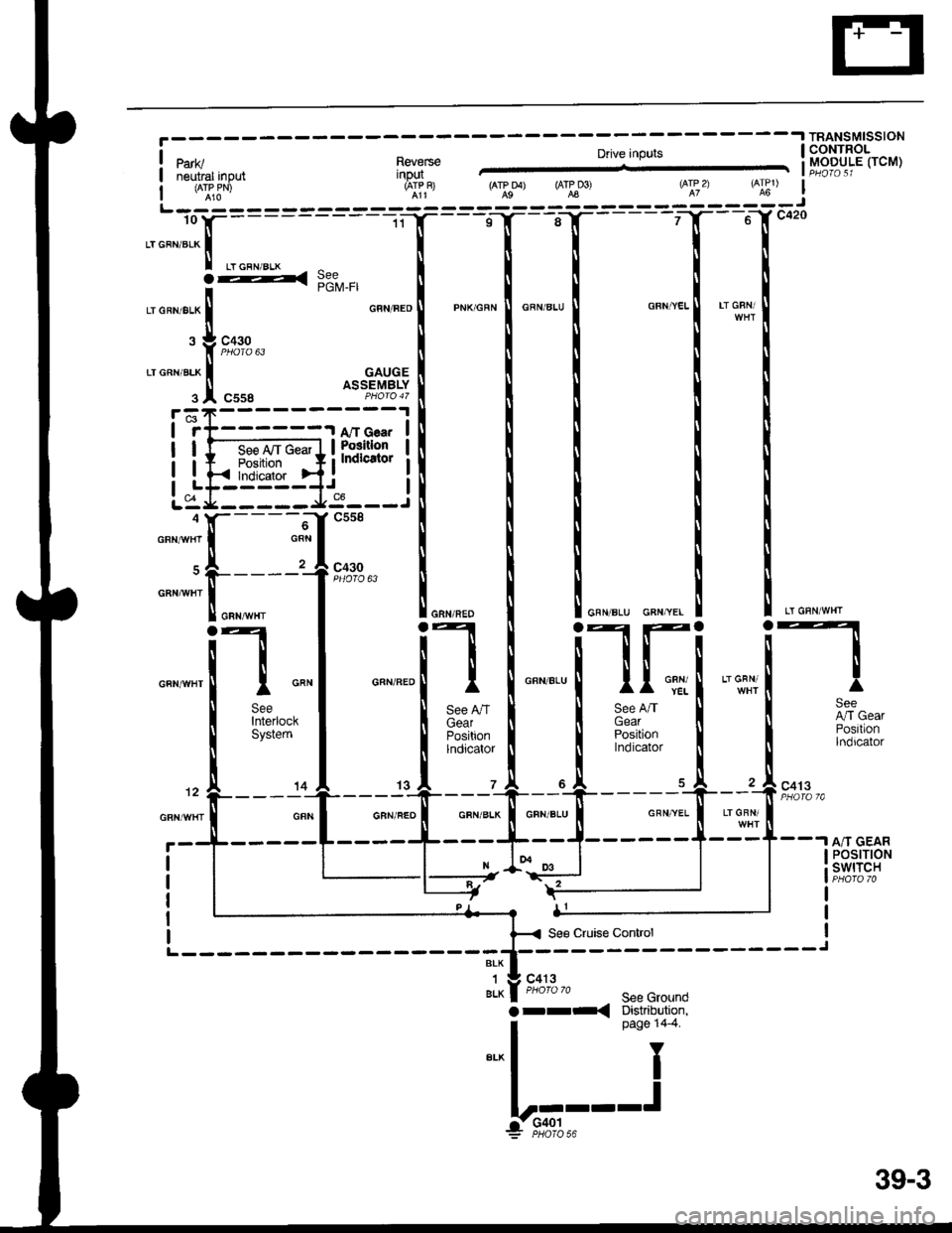
.I TRANSMISSION
r -.. Drive inputs l9.9ITn9!-^..,
neutralinput ir'^'tr -.".".._...............'- |(ArppNl ii#nr GTP-o4l (ATf^o3r rArPzr rAlft' Ialo Ar I A9 pA Ar 46
i MODULE (rCM)
LT GRN/WHT
ltIA
SeeA/T GearPositionlndrcator
ra
I
I
IF.4_mlffi:xrir,L
La)L-----g---i
c558
c430PHOfO 63
*"."1r---
'F--
cnN^'rHr iI GRNATVHTI GRN/BEDa-a
[f GRN"".,"."1f,
See A,rTGearPositionlndicator
7c413
- --I A/T GEAR
I POSTTTON
i swlTcHI PHA|A /0
I
I
IJ
BLK
1BLXc413
arrr< Distribution,
".^
I
pase144
b#^:--,J
See Ground
39-3
Page 1462 of 1681
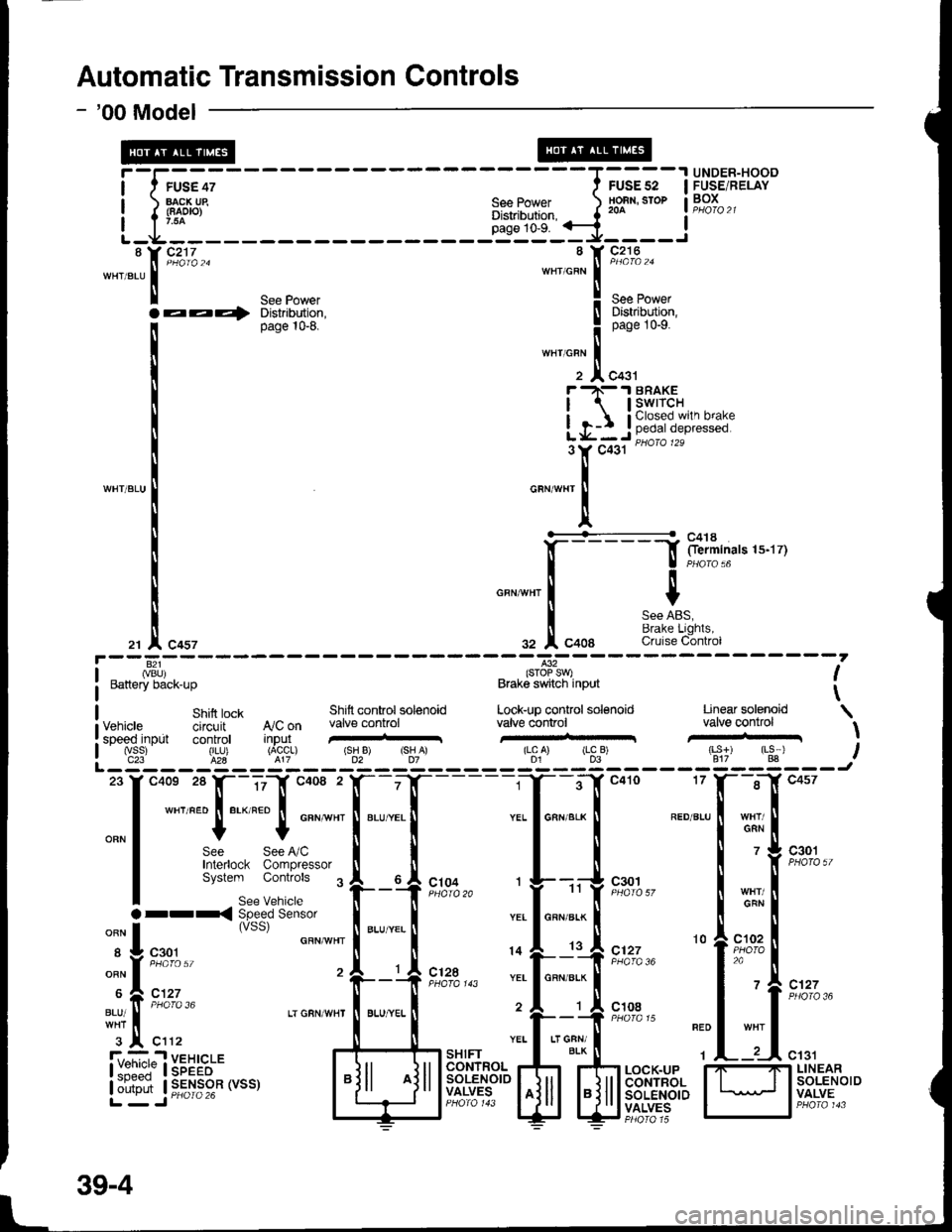
Automatic Transmission Controls
- '00 Model
47n
24
FUSE 4AACX UE(8ADrO)
c2't7
'r,
Ir.g
l
See PowerDistribution,pag€ 1G9.
FUSE 52HOBfl, SIOP204
UNDER-HOODFUSE/BELAYBOX
c418Oerminals 15.17)
8
WHT/AIU
aa+See PowerDistfibution,page 10"8.
I
$See ABS,Brake Lights,Cruise Control
. B2t 432r--rsrbFswlIBattery back-up Btake switch input i
Shift lock Shilt conkol solenoid Lock-up control solenoid Linear solenoid \Vehicte JirCuif ly'C on valve control valve control valve eontrol Isoeed inDut control inDut !speed input control inputlvss) {rLUl tacoLl {SH B, rSH A' {LC A) (LC B) {L.s+J (LS ) Ic23 A2A At7 02 D7 Dl D3 817 8a -'c23 A28 A17 02 D7 D1 D3 817 88
T-lF$ffiT-il:
::m]'::.
1j$;$d.H-t,il: Tfl;;
ill}.-.'.-":[-{,* 'ffi; -lTl.'
i[fi;"
":ff":'[:{;,[fi::
iy:[*i xFEf"* llrTril ilfinpl -l-
"'i-f1.o"^.,,
i i--i , !r.Eli- -
L'q,j ;:i5?" *'.,
|
"ll!
i ll
I tf.f$sb
E W *$+iir [E''l
5i'i+r" "
I see venicre
-
|_
- -T ;'r'o'i;
i;*
**'""::.";
I
""
l'tr .,,,
"^::'[",,
39-4
Page 1464 of 1681
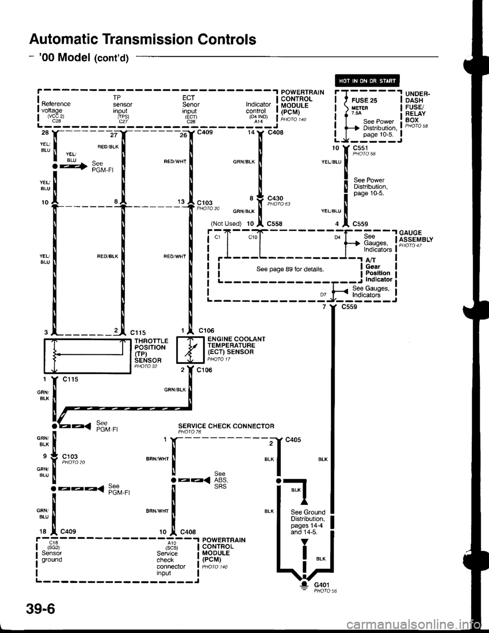
Automatic Transmission Controls
- '00 Model (cont'd)
[---;""'.f
-lc+os 141' c4o8 LJ-:*:IJ
|
:t
, ;:".1
*"",",1 "**-
I
-.11,[t*r'""
I .l ,.,1,","" .J,o*". i
r*ru;l
i.";-
- - -
Is"*
- - - - -
Fsil
- - -
;; I i.l{T'Fil^'- i I ;;
- -
I Ui3"*I voltage Inout
L js!'- - - - - - d": - - - - - 3t - - - - - roql j Hili:
i i-Ti*.*,*,, i F"H*i,'ll-------zrI_------16'rc4os 14tr' c408 LJ_j*::J
:tt, I ".ou.*l I I
r rii ^ r "."-,. r ^""",. r ". ::[ 9#3-
**[
[ [ X"., !r*g+;l"f-----
t
't
l;:,.il*[;,;
""T1",,,""
! ! !i;T-"{_
___-}.[1dnw'"t*il *"*-l "'o*n'l i'I---L-
I I NLi::--::::-:=a-*$$ti
.l_______l ",,, ,l ",,.
'r "*'
I_ITI ENGINE COOLANT
iddirioil I Jr l,.g:tilu;SENSOR lJJal PHora 17
c106
GFN/BLK
SERVICE CHECK CONNECTORPHOIO 76
-"^,:,[
.:
"{
'T[_:'*' "..1
;*liil, lFffi*'" I
c405
BLI
BLK I
I'
See GroundDistribution,pages 14-4and 14-5.
V
I ..
G401
39-6
Page 1503 of 1681
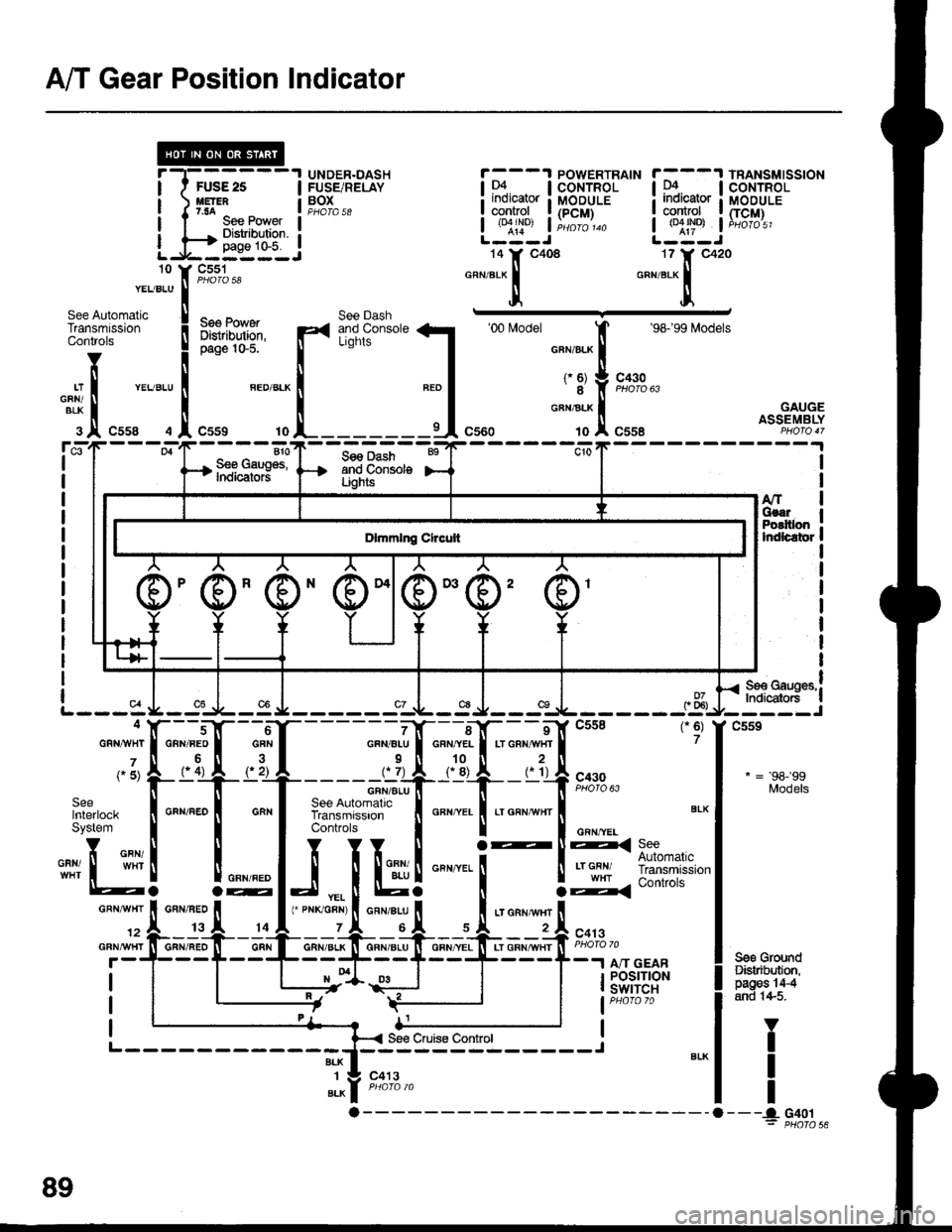
A/T Gear Position Indicator
UNDER.DASHFUSE/RELAYBOXPHOTA 58
POWERTRAIN TRANSMISSION
I D4. I coNrRoL | tr. lcoNrRoL
L$"r:j HS}H Lrulij
frBfii:'
*-1.'-f,"*' *,::-f,"*'c551
Ses PowatDislribution,page 10-5.
See Dashand ConsoleLights
'00 l4odel
't0
:ql
'98'�99 [4odels
c430
c558
410S€e Gaug€s,lndicators
See Dashand ConsolaLights
GAUGEASSEMBLY
A/r IGsa. IPoEltlon :lrdlcator I
I
I
I
I
I
I
I-t**r*",!
Indicdo6 |
I
I
L---ac9
c559
* = 98-99Models
Sgs GroundDistributon,pages 'l4{
and 1+5.
4
GRNAVHT
(" 5)
SeelnterlockSystem
Yi GBN/",i,ll I wHr
'12
GFNA!/HT
c413BLK1
BLK
V
T
I
I- - --a_ G40 t= PHOTO 56a
See PowerDiBaibution.
89
Page 1504 of 1681
- How the Circuit Works
With the ignition switch in ON (ll) or START (lll),
voltage is applied to the A,/T gear position indicator.
The A,/T gear position switch provides a ground for
each position. As an input is grounded, ils indicator
light comes on. lf you se,ecl B, tor example, ground
will be applied to the input of the A,/T gear position
indicator, and the R indicator bulb will come on.
With the headlight switch in PARK or HEAD, voltage
is applied to the RED/BLK wire terminal. this
changes the indicator panel illumination from lixed
to controlled by the dash lights dimmer inpul
through the RED wire.
When the lransmission ('98.�99 models) or
powertrain ('00 model) control module (TCM or
PCM) detects an abnormality in the automatic
transmission control system, or when you request
diagnostic trouble codes through the service
check connector, the TCM or PCM will make lhe D4
indicator light blink.
Refer to the Service Manual (Section 14,
Automatic Transmission) for soecific tests or
troubleshooting procedures.
89-1
Page 1513 of 1681
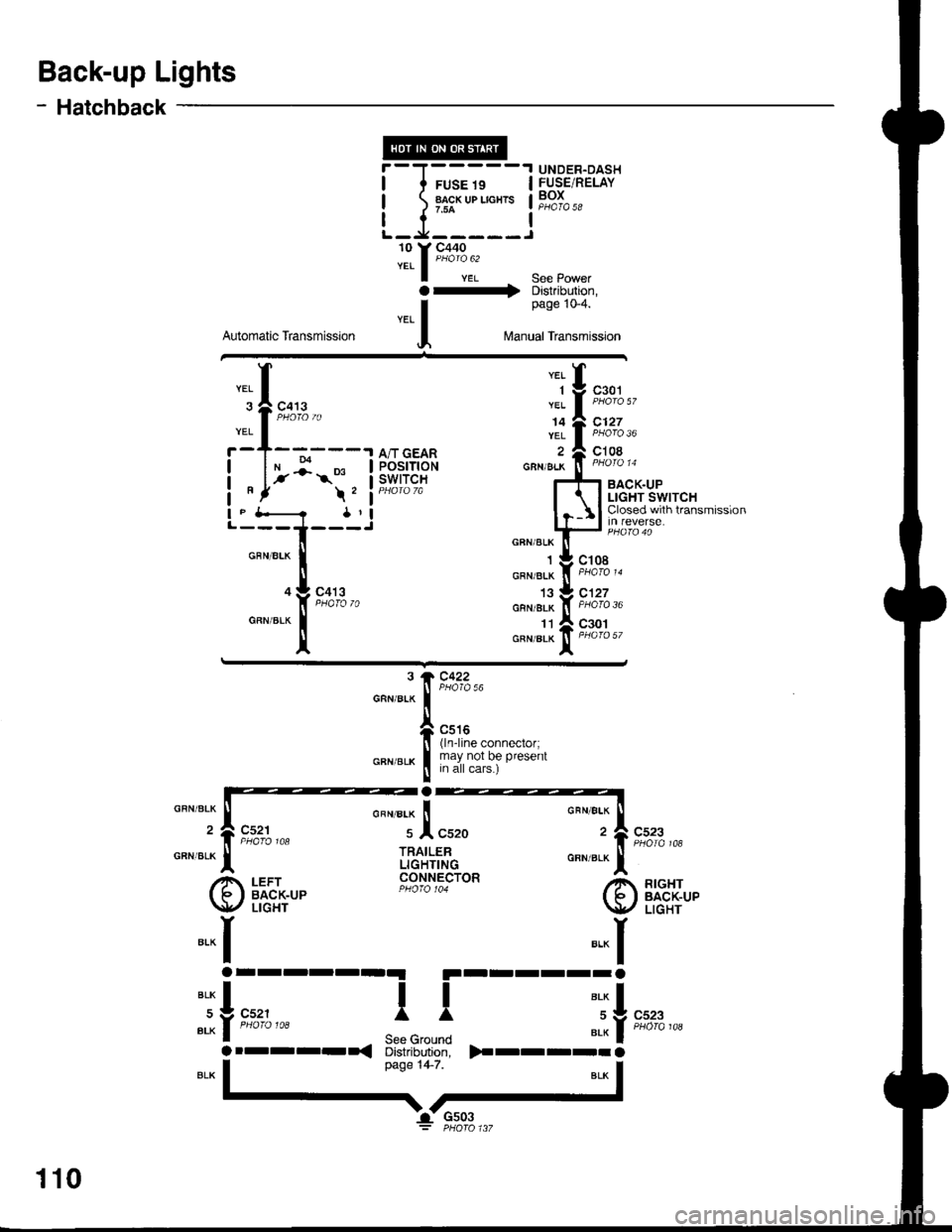
Back-up Lights
-.I UNDER.DASH
I I ruSr rs I FUSETRELAY
| ! 1;" ," uo"'. I F"?T" *
I i- |L-J-----J'o Y "c,fl13.,YEL I YEL s€e powsr
a- Distribution,
- Hatchback
Automatic Transmission
page 10-4.
l\4anual Transmission
*'l
A/T GEARPOSITIONswtTcH
.=L=r-.
!"1"''1,!
.frl_.j
Io
BLKYeLr
I.II-II'
"Tt
"*,
erx I eaoro roa
arrrr-<
"'i
U "ro'':;^::;:"
"""1:i*#J;;;"
r# aacr-upI 1 | LrcHT swrrcH
I t _ | l]"^#1,;:. tra.lsm,ss,on
o"n,".*F "noto t'
","'"J, fi ";o'8"
""",J; fi F;%,,
"""JIft 9,:%,,
""-".t- [
t*'
fi f,f.l,l" "onn"",o.,
*" *_
I ilil,?:lli 0,"""",
o"n".*!ffi;-'l
,lF;,;,,,
:l::. ,fffi:,*
canre.*l i$itdq o"n".*f
@ l.:{;*-," ""g#'"'c'o*
@
g.[H,,.
rt
IA
F
I
See GroundDistribution,page 14-7.
G503
"Tt
"u,.
au I Puoto 'oe
Frrrrra
110
BLK
Page 1514 of 1681
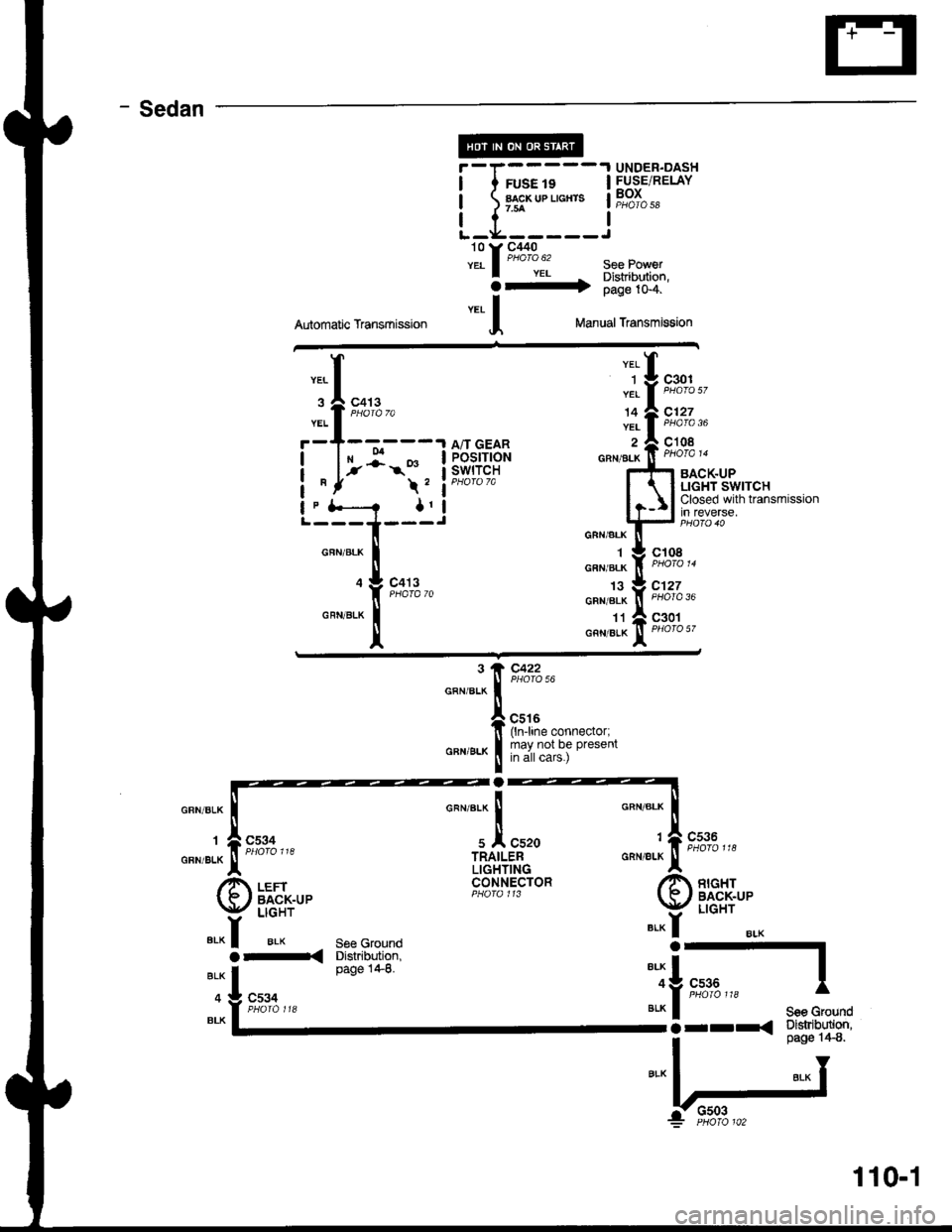
- Sedan
Automatic Transmission
:ibi"lf:li::",""
I
I
I
I
.$t=t
i " j'*'-1,
| " &---? ar
",::i'*
'
A/T GEARPOStTtONSWITCH
3 .i c422
n"n,".^ |
"'oto'u
* tf-l:" "o"""",o,,
o"n,".^
! il?,l?lli o'""""'
o"n ur* | o"n ".* [
o"*"*
|
t *"";%,,, u l"uro ...^.lln*,,,cn,r ar-x .ff
-"" " '"
Hl+irT" GRN 8tx )t
@i[r"t"
coNNtcroR
Qphft,"
".*f af,,. - see crou!.c
"*!#
a-< Distribution, _.._ I"ri:3rr:''*sr ri;;;'l
^:"Y9;%,,, ".^| """'
s€ecround
:---< 3lflit8:'
G503PHO|O 102
'i[,rr*,'
i,!,.1t;"%""
o"",".?frFH''Ffi elcr.up
| | r-rcxr swncx
I t_rl fi,ffi$#1, transm'ssion
o"n,".*F "'oto oo
*",Jf, F;0,3,"
""",Jlt "";t%,.
""""'Jf "";%"
110-1
Page 1558 of 1681
lnterlock System
- How the Circuit Works
Key Interlock
Battery voltage is supplied at all times through f use
33 to the key interlock switch. When the key is in
the ignition, battery voltage is supplied to the key
intedock solenoid and the key interlock circuit in the
interlock control unit. When the A/T gear position
switch is in PABK, ground is provided to the key
interlock circuit. This removes ground from the
interlock solenoid, the solenoid is deenergized, and
the key can be removed from the ignition.
Shift Position Interlock
Battery voltage is supplied at all times lrom fuse 52
to the brake switch. With the ignition in ON (ll) or
START (lll), battery voltage is supplied through luse
25 to the shift lock solenoid. When you push the
brake pedal, battery voltage is applied through the
GRN/VVHT wire to the transmission ('98-�99 models)
or powertrain ('00 model) control module (TCM or
PCM). lf, at the same time, you do not push the
accelerator pedal, a low voltage signal is sent
through the RED/BLK wire to the TCM or PCM. The
TCM or PCM then applies voltage through the
WHT/RED wire to the shift lock circuit in the
interlock control unit. lf the A,/T gear position switch
is in the PARK position, the shift lock circuit
provides ground to the shift lock solenoid. The
solenoid is then energized, and the shift lever can
be moved from the PARK Dosition.
Refer to the Service Manual (Section 23, Electrical)
for specific tests or troubleshooting procedures.
138-2
Page 1569 of 1681

Component Location
b-
13. Right Front Corner of Engine Compartment16. Right Side of Engine (GS-R Shown, Others Similar)
14. Top Front of Manual Transmission17. Right Side of Engine (All Except GS-R)
15, Top Front ot Automatic Transmission18. Right Side of Engine (GS-R)
l201-2