Transmission HONDA INTEGRA 1998 4.G Workshop Manual
[x] Cancel search | Manufacturer: HONDA, Model Year: 1998, Model line: INTEGRA, Model: HONDA INTEGRA 1998 4.GPages: 1681, PDF Size: 54.22 MB
Page 1387 of 1681
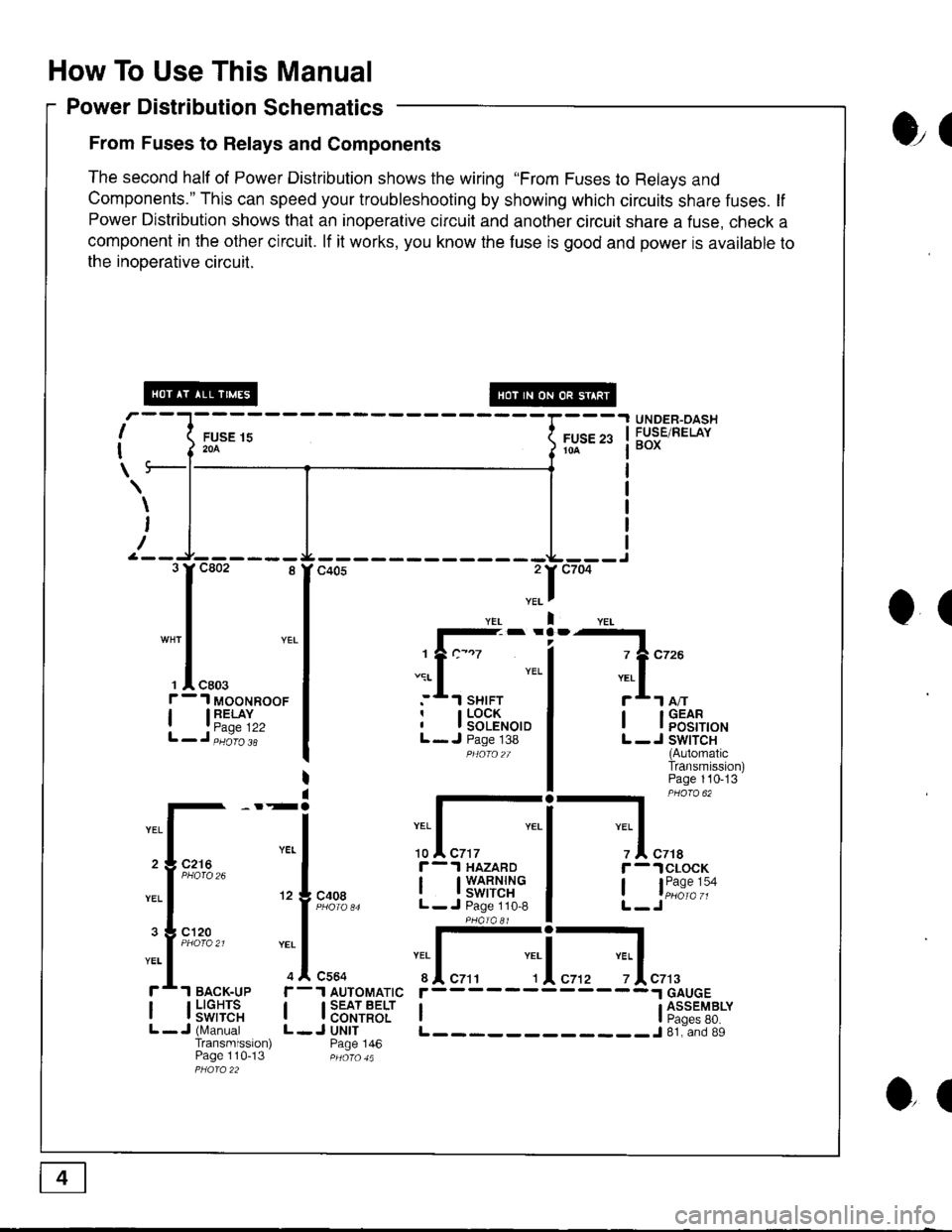
How To Use This Manual
Power Distribution Schematics
From Fuses to Relays and Components
The second half of Power Distribution shows the wiring "From Fuses to Relays and
Components." This can speed your troubleshooting by showing which circuits share fuses. lf
Power Distribution shows that an inoperative circuit and another circuit share a fuse, check a
component in the other circuit. lf it works, you know the fuse is good and power is available to
the inooerative circuil.
ol
I
I
\
FUSE 15204
UNDER-OASHFUSE/RELAYBOXFUSE 2310A
\
I
/
O(
.II
l-- -
1?c-.7
.:r- I YEL
:*.l sHrFTr I LOCKI I SOLENOIDL- J Page 138PHOfO2T
I lFEt[,o'
L -J SWITCH(AutomaticTransmission)Page 110-13
-l PHaro 62
IYEL Iz I czrar -.lclocK
, l"i1:"':oL-Jc408
r-.l HAZARD
I t3'�S[t''i"L- J Page 110,8
:I-c564
1 AUTOMATIC
I SEAT BELTI CONTROLJ UNITPage 146
YEI
r
IL
c7t3
I l5"f,TE'"L -J (N,4anualTransmission)Page 110-13
r------
I ti:*'"T8*L____________J 81. and 89
3rc802 8
I
"* | YEL
I
', I "ro.f - 1 MooNRooF
| 13"'^TI",L-J,iiio'i'
2 3 C216
3 g cl20
ol
Page 1391 of 1681
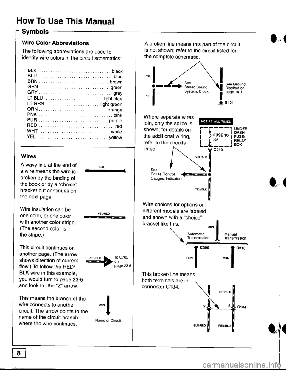
How To Use This Manual
Symbols
Q,(Wire Color Abbreviations
The following abbreviations are used to
identify wire colors in the circuit schematics:
BLK.... .........btack
BLU.... ......... btueBRN .... ........ brown
GRN.... ........ green
GRY .... ......... gray
LTBLU . ..... tighrbtue
LTGRN. ....ljghtgreen
ORN.... ....... orangePNK.... ..........pink
PUR .... ........ purpte
RED .... .......... redwHT... .,.......white
YEL .... ........ ye ow
A broken line means this part ot the circuit
is not shown; reler to the circuit listed for
the complete schematic.
",.I
ar
*.1
See GroundDistribution,page 14-1.
1G101
Where separate wires
join, only the splice is
shown; for details on
the additional wiring,
refer to the circuits
listed.i-l{:i
;["
UNDER.DASHFUSE/RELAYBOX
Wires
A wavy line at the end of
a wrre means the wire is
broken by the binding of
the book or by a "choice"
bracket but continues on
the next page.
Wire insulation can be
one color, or one color
with another color stripe.
(The second color is
the stripe.)
This circuit continues on
another page. (The arrow
shows direction of current
flow.) To follow the RED/
BLK wire in this example,
you would turn to page 23-5
and look for the "2" aftow.
This means the branch of the
wire connects to another
circuit. The arrow points to the
name of the circuit branch
where the wire continues.
BLK-Crulse Controt, QaalGauges, Indrcarors
!YEUBTK
II
Wire choices for options or
different models are labeled
and shown with a "choice"
This broken line means
both terminals are in
connector C134.
bracketlikethis
*J
Q,(
ManualTransmission
*'ffil:,*"1"' *"1""0
I
"""1
H
Name of Circuit
cl34
a,ll
Page 1406 of 1681
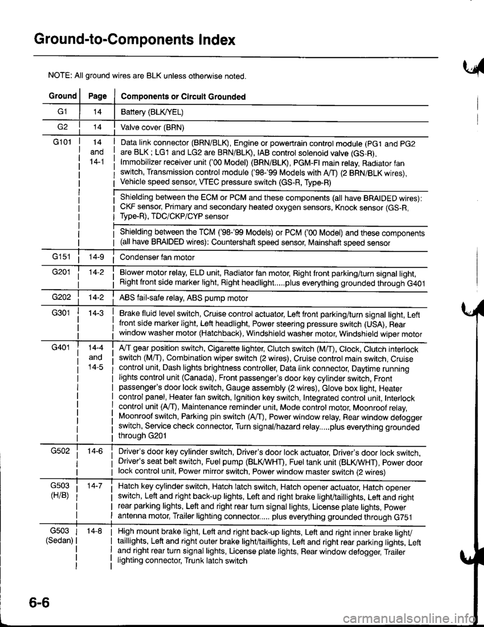
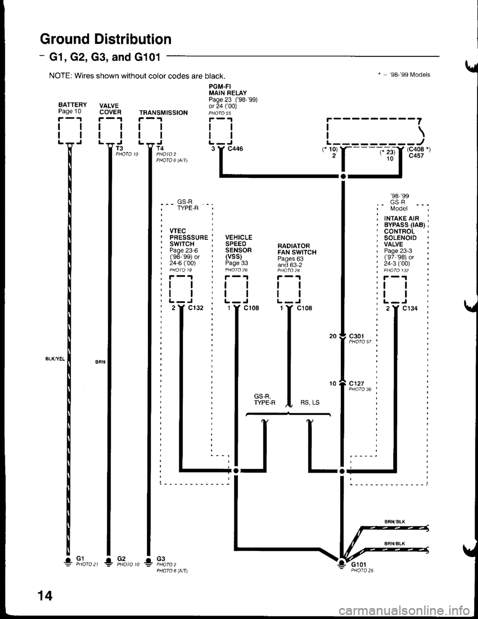
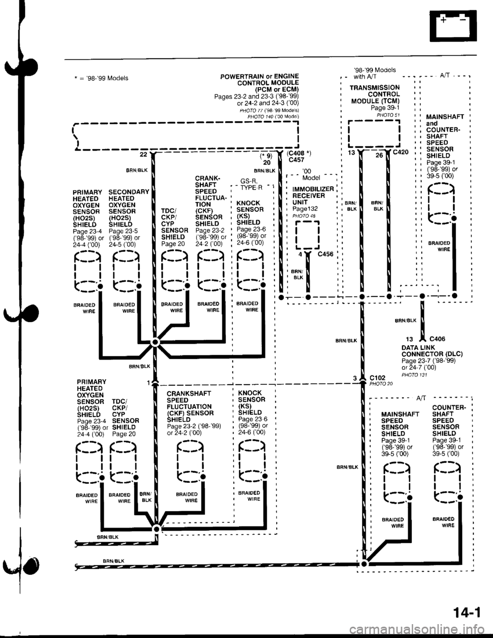
Ground-to-Components I ndex
NOTE: All ground wires are BLK unless otherwise noted.
GroundPageComponents or Circuit Grounded
Battery (BLIVYEL)
--t'I Valve cover (BRN)
G101t.+
and
14-1
Daia link connector (BRN/BLK), Engine or powertrain controt module (pct and pG2
are BLK; LG1 and LG2 are BRN/BLR, IAB controt solenoid valve (GS-B),
lmmobilizer receiver unit ('00 Model) (BRN/BLR, PGM-Ft main retay, Radiator fan
switch, Transmission control module ('98.�99 Models with MD (2 BRN/BLK wires),
Vehicle speed sensor, WEC pressure switch (GS-R, Type-R)
Shielding between the ECM or PCM and these components (all have BRAIDED wires):
CKF sensor, Primary and secondary heated oxygen sensors, Knock sensor (GS-R,
Type-R), TDC/CKP/CYP sensor
Shielding between the TCM ('98-'99 Models) or PCM ('00 Model) and these components(all have BRAIDED wires): Countershaft speed sensor, Mainshaft speed sensor
G1s1 ii Condenser fan motor
Brake fluid level switch, Cruise control actuator, Left front parking/turn signal light, Left
front side marker light, Left headlight, Power steering pressure switch (USA), Rear
window washer motor (Hatchback), Windshield washer motor, Windshield wiper motor
14-3
Blower motor relay, ELD unit, Badiator fan motor, Right front parking/turn signal light,
Right front side marker light, Right headlight.....plus everything grounded through G401
ABS fail-safe relay, ABS pump motor
G40114-4
ano
l4-c
A,/T gear position switch, Cigarette lighter, Clutch switch (M,/T), Ctock, Ctutch interlock
switch (MfD, Combination wiper switch (2 wires), Cruise control main switch, Cruise
control unit, Dash lights brightness controller, Data link connector, Daytime running
lights control unit (Canada), Front passenger's door key cylinder switch, Frontpassenger's door lock switch, Gauge assembly (2 wires), Glove box light, Heater
control panel, Heater tan switch, lgnition key switch, Integrated control unit, Interlock
control unit (AfI), Maintenance reminder unit, Mode control motor, Moonroof relay,
Moonroof switch, Parking pin switch (AfD, Power window relay, Rear window defogger
switch, Service check connector, Turn signal/hazard relay.....plus everything grounded
throuoh G201
Driver's door key cylinder switch, Driver's door lock actuator, Drivels door lock switch,Driver's seat belt switch, Fuel pump (BLI(/WHT), Fuel tank unit (BLI(/WHT), power doorlock control unit, Power mirror switch, Power window master switch (2 wires)
Hatch key cylinder switch, Hatch latch switch, Hatch opener actuator, Hatch ooener
switch, Left and right back-up lights, Left and right brake light/taillights, Lett and right
rear parking lights, Left and right rear turn signal lights, License plate lights, power
antenna motor, Trailer lighting connector..... plus everything grounded through G751
6-6
'14-8G503
(Sedan)
High mount brake light, Left and right back-up lights, Lett and right inner brake tighv
taillights, Left and right outer brake light/taittights, Left and right rear parking tights, Leftand right rear turn signal lights, License plate lights, Rear window detogger, Trailer
lighting connector, Trunk latch switch
Page 1411 of 1681
I
I
\
i
FUSE 14(cFUlsEcorrEoLl
FUSE 15alTEaxAron8P SEt{904?.54
UNDER.DASHFUSE/RELAYBOX
\
I
I
8
BLl(YEI
c504
C551 (Not 18
floro used)c551 12PHOfO 58
c560
GAUGEASSEMBLYPages 22-1and 80-2
c440
:l
c410
c440 '12
PHO|O 625A
BLK/WH'
c417 I l' C555
tl
llL--J L--JCRUISE CRUISECONTROL CONTROLUNIT MAINPage 34 SWITCHPHaro s5 Page 34
i#r'
14
tl
BLK I 8lK lt Y pHoto5l ,YEL I YEL I -..-",-. I
:;;:t:i;r
r[-;:i-j:t ;i
".-.,..f,
t'to"
i I ii i'L'lt
BLK/^YEL
12 g c301
c127
tl
ALTERNATORPage 22
,I
SECONDARYHEATED OXYGENSENSOR (H02S)Page 23 5 ('97-�98)or 24-5 ('00)
I er-xi, YEL
9 4 C421
4 g c510
":'.!.^--^ I : I :"1'I^-^- i""! ",",. ;i
"".%',3,. ! : I :'f,,"#5."1 !;I; ;i
i.,II i :l',JI .1',IT :i'Ll ! :1,T.1 r"'Ll i V | :i
c7s3 ,l"rro i ,4"'.0 ' ,,1[s112 izsrz [ ^---:lf :f^--:]r A czgs zlczzq i zAcrgq ' 2Ac1't2 ' 25 X- -':-A c420:' | 1Ac2r8
[l i--l ii--l ii--l ii-----l ii!i'--l| | r | :t | ' I I :t ! ':l!
| | | | rl l:l | :l l:;alL--i L--.r I L--j , !--r : L-----r ,i i r-=l ,EVAPORATIVE EVAPORATIVE ' IHTAXC : VEHICLE : TRANSMISSION :; ; EIEqTRICAL
EMISSION EMISSION , AtR ; SPEED ' CONTROL :' ! !o49 -: BypASS , SENSOR ' MODULE fiCM):'! !%9
ie.vfD- F!Afl,-. ; iiiirss : 9F,lIioR ' l|oDtllEficM) ;:l LTl9.r.?f
I
bvpads aoNThoL i rAat- ' (vss) ' Pase 3s 1 ': i (ELD)-uNlr
soLENolD caNlsTER ; bor.!n.o1 ' Page 33 ', euo,o,, :: I l.?^s_"^l?VALVE VENTSHUT , SOLENOTD , pHora 26 , :,4 Ptloro 23 |Paoe 23-5 VALVE ' VALVE ;' L--- - J(96-99) Page23-5 i paqe 24-5 | : 'IUNDER-HOODor24-5(00) f98- 99) , pdato t32 : : ':FUSE/RELAYorz+-3(uul (Yo-w/ | pHaro 132 :, FusPHoro 136 or 24 5 ('00) : , BOXu,.eJ\vv/PHOfO 139 | ,t PHOTO21
l--33. -j :-- ee-�ss lvodels --:l---.usA ---
Model
:lrt I
; POWER-, TRAIN' CONTROL' MODULE
: (PCM), Page 39-5
, '00
, Model'- with -.,lo
10-3
Page 1419 of 1681
TRANSMISSION
I
I
T4
PGM-FIMAIN RELAYPage 23 ('98-'99)or 24 ( 00)
tl
tlL-J
* : '98-'99 Models
i---------\L---------J(- 10) r-- -;-;.11, (c408.)(- 23)10
'98- 99.. GS.R' l/odel
inrrarerrn i
I
I
.-- GS-R. TYPE.R
VEHICLESPEEDSENSORRADIATOBFAN SWITCH
and 63 2
tl
tlL-Jcl08
(vss)Page
PHATO 6IIITJ
I
I
33
I
I
c3o1 ;
10
Ground Distribution
NOTE: Wires shown without color codes are black.
VALVECOVER
I
I
- G1, G2, G3, and G101
I
I
T3
BATTERYPage 10
r-'r
tl
ll'n'
I
I
I
I
I*-*rl
I
I
I
I
! F,to,o^_l1io,o,o *
14
Page 1420 of 1681
* = '98-'99 L4odelsPOWERTRAIN or ENGINECONTROL MOOULE(PCM or ECM)Paqes 23-2 and 23'3 ('98-'99)- or 24-2 and 24-3 ('00)
PHOTO // f98 99 Models)
'98' 99 l\4odels
TRANSMISSIONCONTROLMODULE (TCM)Page 39-1PBA|O 51
--".-- A/T.--,
PHA|A 144 100 Made )
rl\lI&------ ---------J
26'� I c4s7
L----J
c102PHO|O20
MAINSHAFTanoCOUNTER.SHAFTSPEEDSENSORSHIELDPage 39-1('98-'�gs) or39-s [oo)
COUNTER-SHAFTSPEEDSENSORSHIELDPage 39-1('98-'�sg) or3e-5 f00)
BBN/BLK
PRIMARY SECONDARYHEATEO HEATEOOXYGEN OXYGENSENSOR SENSOR(HO2S) (HO2S)SHIELD SHIELDPage 23-4 Page 23-5('98-'99) or ('98-'99) or24-4 ('�00) 24-5 f00)
AFN/BLK
PBIMARY 'l
HEATEDOXYGENSENSOR TDC/(HO2S) CKP/SHIELD CYPPaqe 23-4 SENSOR('96- 99) or SHIELD24 4 ('00) Page 20
BRN/BLK
CRANK- ne_FSHAFT . - ii'pilp -i
SPEEDFLUCTUA-
CKP/CYPSENSORSHIELOPage 20
l1
ll
k::!
T|ON 'KNOCK
(cKF} : SENSORSENSoR . (KS)SHTELD , SHIELDpaoe 23-2 ' Page 23'6(96- 99) or ' (98-99) or
24 2 (OOt : 24-6 ('�00)
r::)f::l i(::)
l::i iL:l
r::)
tt
tl
(- ,:o
BRATDED IWIFE I
lltl
k--'a
illBFAIDEOWIBEBFAIDEDWIRE
AFCRANKSHAFTSPEEDFLUCTUATION(cKF) SENSORSHIELDPage 23-2 (98-99)ot 24-2 (00)
. KNOCK, SENSOR,(Ks),SHIELD
| 1se:'ss; or, 24,6 ('�00)
ir::)
MAINSHAFTSPEEDSENSORSHIELDPage 39-1('s8-'99)or3e-s ('00)c:) r::)
I
I
k:::
ll
tl
.k
(::)
ll
tl
kIt::
I
I
a
(::)
tl
ll
(::::BRAIOEOBFN/BLKBNAIDEO
:l I;l I
BNAIDED
:kll::
' BFAIDEO
i: (::)
::l I,' I I
iiffil
.---a--,--o
I""","j-.!,
"oo.
DATA LINKcoNNECTOR (DLCIPage 23-7 ('S8-'99)or 24-7 ('00)
(DLC)
BFAIDEDWIFE
14-1
Page 1431 of 1681
- Automatic Transmission
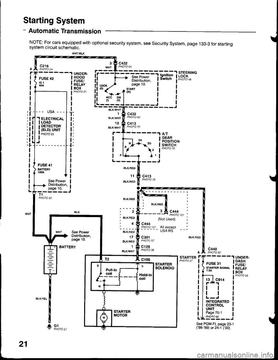
NorE: For cars equipped with optional security system, see security system, page 13g-3 tor startrngsystem circuit schematic.
Starting System
c216
FUSE 42tGt
UNDER-HOODFUSE/RELAYBOX
See PowerDistributian,page 10.
liu.) 3:i:it1-i*!
i!'''{=o1ili"' i i!i (=r.f(',ii i I
!i rfi,l.l i I
!L----J------j Ir'---BLK;HrT---------=---r
".o"rnrfi F,i% u.,
'to A co' s
3 V C432
BLr!,Y/Ht ll PHoro 70
04-;' s
\z
1l
t:
t,
t;
t:
t:
t,N^/.
A,/TGEARPOSITIONswtTcH
ALKFEO
't1
EIIVRED
BLKFED
t2
I BLK/RED
'4
BLI(FED
178LK/BEO'I
BLKII/HT
FUSE 41BATTEiYr00A
To
c413
See PowetDistribution,page 10.--i--;-JT1
BATTERY
c444
{Not Used)
All exceplUSA FS
c301
c126PHOTO 36c4404 ^, PHO|O 62
STARTERrrF-----1
! i rur..r !| snnrea sour- || 1 '* |
! Ir-'Lg"' i
llttl
llr | |
llL-J Ir I INTEGRATEo I! I CONTROL I
I luNrr I
tIbEt:_J
UNDER-DASHFUSE/RELAYBOX
WHT/ALK
--- usA ---
.I ELECTBTCALI LOADI DETECTOR
i (ELD) uNrr. PHOIO 23I
21
lGlSee PGM-FI, paqe 23.1('98.'99) or 24-1I OO).
Page 1432 of 1681
![HONDA INTEGRA 1998 4.G Workshop Manual - Manual Transmission
NOTE: For cars equipped with optional security system, see security system, page 133-3 for starting
system circuit schematic.
c432
FUSE 42tGl
c216
r
I
I
I
I
I
I
I
I
I
]
UNDER.HOO HONDA INTEGRA 1998 4.G Workshop Manual - Manual Transmission
NOTE: For cars equipped with optional security system, see security system, page 133-3 for starting
system circuit schematic.
c432
FUSE 42tGl
c216
r
I
I
I
I
I
I
I
I
I
]
UNDER.HOO](/img/13/6069/w960_6069-1431.png)
- Manual Transmission
NOTE: For cars equipped with optional security system, see security system, page 133-3 for starting
system circuit schematic.
c432
FUSE 42tGl
c216
r
I
I
I
I
I
I
I
I
I
]
UNDER.HOODFUSE/RELAYBOX
ELECTRICALloAoDETECTOR(ELD) UN|T
START(10
c432
.Joil0t)
BLKWHT
1
BLK/IVHT
(o) ,t-,>
0)
,i
I
l
Ia
I
I
I
I
BLKA''HT II--2 A cqqz
"4
".u,".0^ tr-
- -----
t I coee
Hifr*',;*-"J
":-r
"*'
: See Ground
I Rl"i:b,*?"
""1;
' PHOIO 56
STARTERCUTRELAY
See PowerDistribution,page 10.
T1PHO|Q22
BLK/REO
BLK/BEO
a=z
lt
lta c444
Used)
c444All exceptUSA RS
See PolYerDistribution,page 10.
BLK/REO
1
ALK/WHI
c301
c126PHOTA 36c440
BATTERYSTARTERrrF-----1
! { H:.i,r'",""^. I
li ?.ea I
!l';Lg" i
|r | |
ill l lllL-J I! I INTEGRATED ]| | coNrRoL I
Ll'l,l't--i
UNDER.DASHFUSE/RELAYBOX
See PGM'Fl, page 23-l('98-99) or 24-1 ('00).
t2 A Clos
-a- G1
21-1
Page 1457 of 1681
Cruise Control (cont'd)
- How the Circuit Works
The cruise control system uses mechanical and
electrical devices to maintain the car's soeed at a
setting selected by the driver.
System Description
The cruise control unit receives command signals
from the cruise control main switch and the cruise
control SevBesume switch. With the ignition switch
in ON (ll) or START (lll), voltage is provided to the
cruise control main switch. When you push the
switch to on, power is provided to the cruise control
unit and the brake switch.
The cruise control unit receives information about
operating conditions from the brake switch, the
ignition control module (lCM), the vehicle speed
sensor (VSS), and the clutch switch (manual
transmission) or the A,/T gear positton switch
(automatic transmission). The cruise control unit
then sends signals to the cruise conirol actuator
which regulates the throttle position to maintain the
selected speed. The control unit compares the
aclual speed of the car to the selected speed. The
control unit then uses the result of that comoarison
to oDen or close the throttle.
The brake switch releases the system's control of
the throttle at the instant you press on the brakepedal. The switch sends a signal to the control unit
by removing power from the normally closed brake
input (GRY wire), and providing power at the
normally open brake input (GRNMHT wire). The
control unit responds by allowing the throttle to
close. The clutch switch or the A/T gear position
switch sends a "disengage" signal to the control unit
that also allows the throttle to close.
The cruise control system will set and automatically
maintain any speed above 25 mph (40 km/h). To set
it, make sure the main switch is on and the switch
indicator is on. Then, after reaching the desired
speed, press the set switch. This sends a "set"
signal to the cruise control unit which, in turn,
controls the cruise control actuator to maintain the
set soeed.
When you push the SET switch and the cruise
control system is on, the "cruise control" ON
indicator lights up.
34-4
You can cancel the cruise control system by
turning the main switch off. This removes power to
the control unit and erases the set sDeed from
memory. lf the system is disengaged temporarily
by the brake switch, or clutch switch, and the car's
speed is still above 25 mph, press the RESUME
switch: the car will automatically return to the
previously set speed.
For gradual acceleration without pressing the
accelerator pedal, push the RESUME switch and
hold it there. This will send an "acceleration" signal
to the control unit. When you release the switch, the
system will be reprogrammed tor the new speed. To
slow the car down, push the SET switch in and hold
it there. This sends a "deceleration" signal to the
control unit, causing the car to coast. When the
desired speed is reached, release the SET switch.
This reprograms the system for the new speed.
Reter to the Service Manual (Section 23, Electrical)
for specific tests or troubleshooting procedures.
Page 1458 of 1681
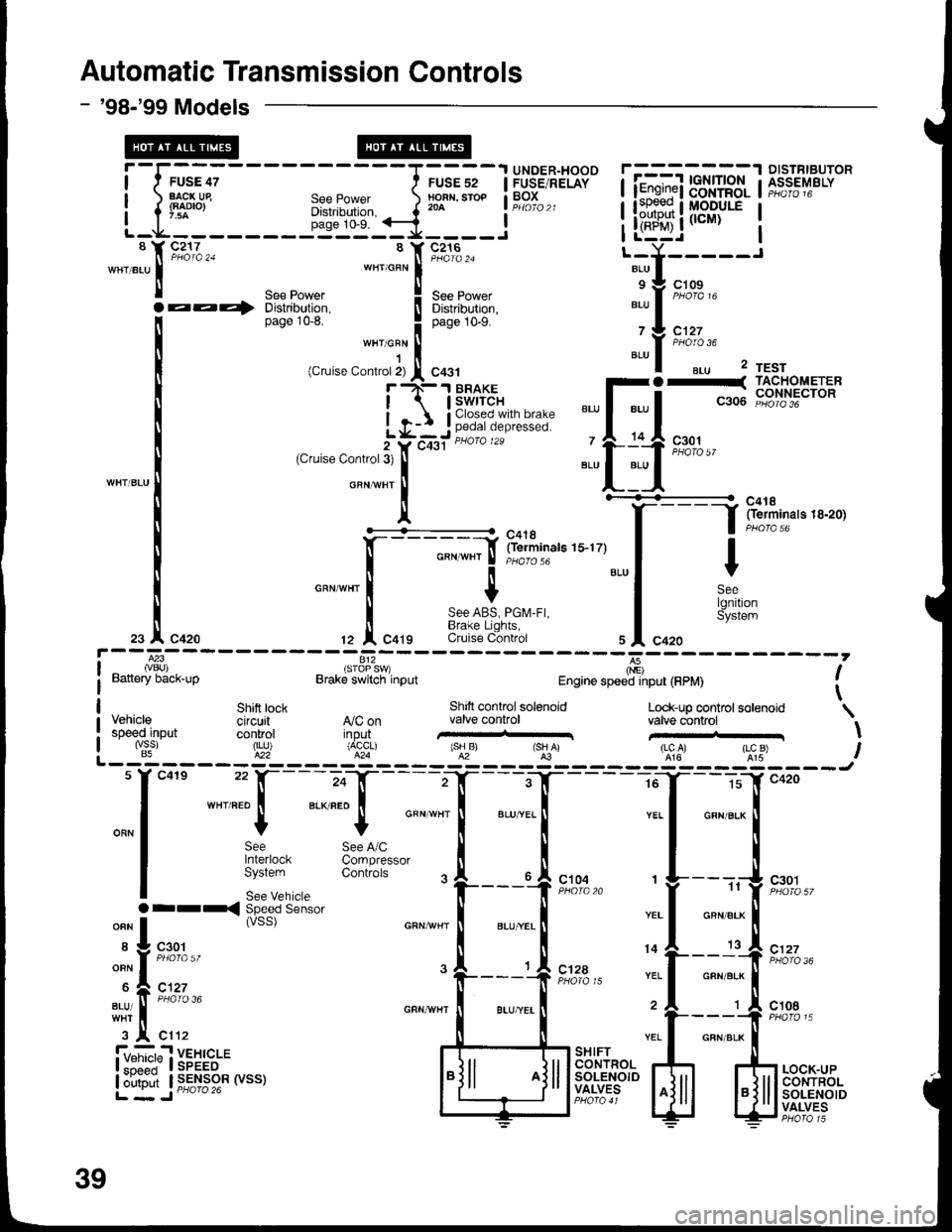
Automatic Transmission Controls
- '98-'99 Models
-I,;;;
EACK Ue
-l'::-
FUSE 52NOFN, STOP204
UNDER-HOODFUSE/RELAYBOXSee PowerDistribution,page 10-9.
isToP s
v)Brake switch input
8c217
aa+
I Y C216ll PHaTa 24wHrcFN iSee Power ! See power
Distribution. I Distributron,page 1G8. I OuO" tO-S.
""t o:"
I(Cruise Contror 2) I C431
r rN-.t BRAKE
I | swrrcH
L q-: j ;,,?i,i?'Y,i *i,i:5"
2Ycqst "u'o '*
(Cfuise Control3t
IGFNvHT
Il'+^..6'f- - - --_- -
:f irlliin"r" r s-r zy
I
GFN wHr I 'r'oro'o
cnrwnr I t
i 8:i^i?i,i":"tZ I Cqtg Cruise C-ontrol
] fii1f,,",.,..,,
Y
SeelgnitionSystem
l---83ivBU)Battery back-up
812',
I(nE)Engine speed input (FPM)
Shitt tock Shift controlsotenoid Look_up coo.trol solenoid \VehiCle Cifcuit A,/C on valve control valve controlspeed-input control ilp"ui' ,-'H...,.,,,,..r \"&. ,j5? ,X%""r' ,"lru' rsHAr 'lgl' ,l:"u) IL _ iq - _ _ _ _ E?_ _ _ _ g'_ _ _ _ 5i _ _ _E: _ _ _ _ _ !t- _ _ _:&: _ _ _ - _tu
f
"0"
-",:: [-;"f
-
"- "T-. -T----=T--_5
"-'
*"
I p*t ^", 3rl**.,*""
-"'
il
-'-..
|
-.
|
"* *^
|
| $:'"::""
33n:Ji.'*' .
|___{ r*,," ,
f----,{ r*:,,
.ri-,-:-
ssc"ds"n'o.
"""**
|
*,"*! ""1 o"n"'* |
*f n';,, . L__J
" [--:'] ,';7..
-.: t "';%,.
-i,.!..,,, ""^"-l'-;;{t**' j:l#r-
iyi,:?n$i,:*""" ffiBB'rI"o."L*.."'.i-ii.*'ji"[!si"""' ,,_r_,"'liiif+:rm U;1f$+f,
:[ilrF""#**F.tr
39